
-
Page 1: Denon AVR-1604
2 We greatly appreciate your purchase of this unit. 2 T o be sure you take maximum advantage of all the features this unit has to offer , read these instructions carefully and use the set properly . Be sure to keep this manual for future reference should any questions or problems arise. “SERIAL NO. PLEASE RECORD UNIT SERIAL NUMBER A TTACHED TO TH[…]
-
Page 2: Denon AVR-1604
2 ENGLISH 2 SAFETY PRECAUTIONS 2 NOTE ON USE / OBSERV A TIONS RELA TIVES A L ’UTILISA TION • Avoid high temperatures. Allow for sufficient heat dispersion when installed on a rack. • Eviter des températures élevées. T enir compte d’une dispersion de chaleur suffisante lors de l’installation sur une étagère. • Handle the power cord […]
-
Page 3: Denon AVR-1604
3 SAFETY INSTRUCTIONS 1. Read Instructions – All the safety and operating instructions should be read before the product is operated. 2. Retain Instructions – The safety and operating instructions should be retained for future reference. 3. Heed Warnings – All warnings on the product and in the operating instructions should be adhered to. 4. […]
-
Page 4: Denon AVR-1604
4 ENGLISH 2 INTRODUCTION 2 ACCESSORIES Thank you for choosing the DENON A/V Surround receiver . This remarkable component has been engineered to provide superb surround sound listening with home theater sources such as DVD, as well as providing outstanding high fidelity reproduction of your favorite m usic sources. As this product is provided with […]
-
Page 5: Denon AVR-1604
5 ENGLISH 3 CAUTIONS ON HANDLING 4 FEA TURES • Switching the input function when input jacks are not connected A clicking noise may be produced if the input function is switched when nothing is connected to the input jacks. If this happens, either turn down the MASTER VOLUME control or connect components to the input jacks. • Muting of PRE OUT […]
-
Page 6: Denon AVR-1604
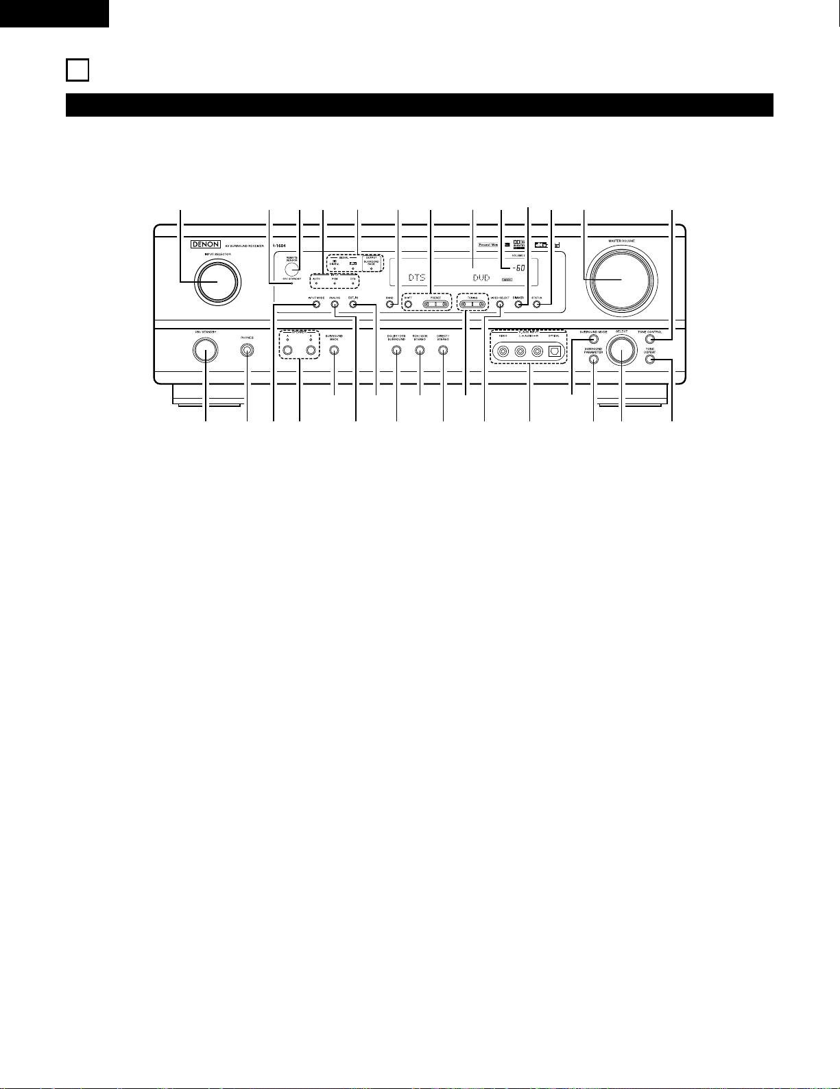
6 ENGLISH 5 P AR T NAMES AND FUNCTIONS Front Panel • For details on the functions of these parts, refer to the pages given in parentheses ( ). q w u e i r y o! 4 t !1 @1 @2 @3 @4 @5 @6 @7 @8 @9 !2 !3 !5 !6 !7 !0 !8 @0 !9 #0 q Power operation switch ……………………………………….(18, 32, 51) w Headphones jack (PHONES)…………..[…]
-
Page 7: Denon AVR-1604
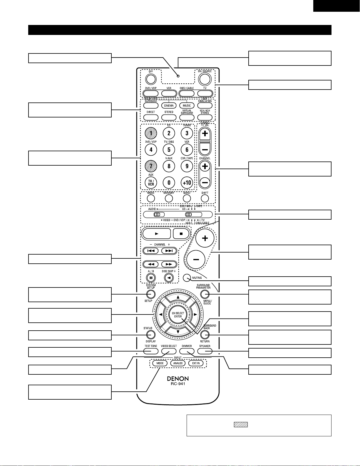
NOTE: • The shaded buttons do not function with the A VR-1604/684. (Nothing happens when they are pressed.) 7 ENGLISH Remote control unit • For details on the functions of these parts, refer to the pages given in parentheses ( ). SURROUND buttons ……………………………..(34, 37, 47) Cursor buttons………………………..(17, 29,[…]
-
Page 8: Denon AVR-1604
8 ENGLISH 6 READ THIS FIRST This A V Surround Receiver must be setup before use. Following these steps. 7 SETTING UP THE SPEAKER SYSTEMS Step 3 (page 17 to 26) Finally , setting up the system. Step 2 (page 16) Next, insert the batteries into the remote control unit. Step 1 (page 8 to 15) Choose the best location to setup the Speakers and connecting[…]
-
Page 9: Denon AVR-1604
9 ENGLISH 8 CONNECTIONS • Do not plug in the power cord until all connections have been completed. • Be sure to connect the left and right channels properly (left with left, right with right). • Insert the plugs securely . Incomplete connections will result in the generation of noise. • Use the AC OUTLETS for audio equipment only . Do not u[…]
-
Page 10: Denon AVR-1604
10 ENGLISH Connecting the video equipments T o connect the video signal, connect using a 75 Ω /ohms video signal cable cord. Using an improper cable can result in a drop in sound quality . IN VIDEO R L R L R L L R R OUT IN AUDIO VIDEO OUT IN LRL R L R L R OUT VIDEO OUT L AUDIO OUT COAXIAL DIGITAL L R R OUT VIDEO OPTICAL OUT L AUDIO OUT DIGITAL L […]
-
Page 11: Denon AVR-1604
11 ENGLISH Connecting a video component equipped with S-video jacks • When marking connections, also refer to the operating instructions of the other components. • A note on the S input jacks The input selectors for the S inputs and pin jack inputs work in conjunction with each other . • Precaution when using S-jacks This unit’ s S-jacks (i[…]
-
Page 12: Denon AVR-1604
12 ENGLISH VIDEO OUT Y C R C B COMPONENT YC R C B VIDEO IN COMPONENT B Connecting a Video Component Equipped with Color Difference (Component — Y , P R /C R , P B /C B ) Video Jacks (DVD Player) • When making connections, also refer to the operating instructions of the other components. • The signals input to the color difference (component) vi[…]
-
Page 13: Denon AVR-1604
13 ENGLISH 1 4 2 3 Connecting the antenna terminals DIRECTION OF BROADCASTING ST A TION AM LOOP ANTENNA (An Accessory) FM ANTENNA GROUND AM OUTDOOR ANTENNA FM INDOOR ANTENNA (An Accessory) 75 Ω /ohms COAXIAL CABLE AM loop antenna assembly Connect to the AM antenna terminals. Bend in the reverse direction. Remove the vinyl tie and take out the con[…]
-
Page 14: Denon AVR-1604
14 ENGLISH Speaker system connections • Connect the speaker terminals with the speakers making sure that like polarities are matched ( < with < , > with > ). Mismatching of polarities will result in weak central sound, unclear orientation of the various instruments, and the sense of direction of the stereo being impaired. • When mak[…]
-
Page 15: Denon AVR-1604
15 ENGLISH Protector circuit • This unit is equipped with a high-speed protection circuit. The purpose of this circuit is to protect the speakers under circumstances such as when the output of the power amplifier is inadvertently short-circuited and a large current flows, when the temperature surrounding the unit becomes unusually high, or when t[…]
-
Page 16: Denon AVR-1604
16 ENGLISH 9 USING THE REMOTE CONTROL UNIT Following the procedure outlined below , insert the batteries before using the remote control unit. Range of operation of the remote control unit Inserting the batteries Point the remote control unit at the remote control sensor as shown on the diagram at the left. NOTES: • The remote control unit can be[…]
-
Page 17: Denon AVR-1604
17 ENGLISH 10 SETTING UP THE SYSTEM • Once all connections with other A V components have been completed as described in “ CONNECTIONS ” (see pages 9 to 15), make the various settings described below on the display . These settings are required to set up the listening room ’ s A V system centered around the this unit. SYSTEM SETUP button Pr[…]
-
Page 18: Denon AVR-1604
18 ENGLISH Before setting up the system 1 2 Press the SYSTEM SETUP button to enter the setting. Check that all the components are correct, then press the POWER operation switch on the main unit or the POWER button on the remote control unit to turn on the power . 3 Press the ENTER or (down) button to switch to the speaker configuration set up. *SYS[…]
-
Page 19: Denon AVR-1604
19 ENGLISH 5 Use the (left) and (right) buttons to select your subwoofer setting. 5 S.WOOFER YES YES NO (left) button (right) button Press the ENTER or (down) button to enter the settings and switch to the subwoofer mode setting. • Parameters Large …… Select this when using speakers that can fully reproduce low sounds of below 80 Hz. Small ?[…]
-
Page 20: Denon AVR-1604
20 ENGLISH NOTES: — Assignment of low frequency signal range — • The signals produced from the subwoofer channel are LFE signals (during playback of Dolby Digital or DTS signals) and the low f requency signal range of channels set to “ SMALL ” in the setup. The low frequency signal range of channels set to “ LARGE ” are produced from […]
-
Page 21: Denon AVR-1604
21 ENGLISH 3 Use the (left) and (right) buttons to set the distance from the center speaker to the listening position. 10 CENTER 12ft • The number changes in units of 1 foot each time one of the buttons is pressed. Select the value closest to the measured distance. Press the ENTER or (down) button to switch to the surround L speakers setting. Set[…]
-
Page 22: Denon AVR-1604
22 ENGLISH 6 Use the (left) and (right) buttons to set the distance from the surround back speakers to the listening position. 13 S.BACK 10ft • The number changes in units of 1 foot each time one of the buttons is pressed. Select the value closest to the measured distance. Press the ENTER or (down) button to switch to the subwoofer setting. 5 Use[…]
-
Page 23: Denon AVR-1604
23 ENGLISH Setting the T est T one • Use this setting to adjust to that the playback level between the different channel is equal. • From the listening position, listen to the test tones produced from the speakers to adjust the level. • The level can also be adjusted directly from the remote control unit. (For details, see page 37.) 1 • Use[…]
-
Page 24: Denon AVR-1604
24 ENGLISH 6 Use the (left) and (right) buttons to set the surround R channel level. AUTO-SR -12dB 0dB +12dB Press the (down) button to switch to the surround back channel level (manual mode). (left) button (right) button 7 Use the (left) and (right) buttons to set the surround back channel level. AUTO-SB -12dB 0dB +12dB Press the (down) button to […]
-
Page 25: Denon AVR-1604
25 ENGLISH NOTE: • TUNER, V . AUX cannot be selected. 3 Use the (left) and (right) buttons to assign the input function connected to the OPTICAL input 2 (OPTICAL 2) terminal. 18 OPT2 TV CD AUX DVD TV VCR CDR OFF • Select “ OFF ” if nothing is connected. Press the ENTER or (down) button to switch the auto surround mode setting. (left) button[…]
-
Page 26: Denon AVR-1604
26 ENGLISH After setting up the system 1 Press the SYSTEM SETUP button to finish system set up. This completes the system setup operations. Once the system is set up, there is no need to make the settings again unless other components or speakers are connected to or the speaker layout is changed. Setting the Auto Surround Mode For the three kinds o[…]
-
Page 27: Denon AVR-1604
27 ENGLISH Operating DENON audio components • T urn on the power of the different components before operating them. 1 2 3 Set mode switch 1 to “ AUDIO ” . Set mode switch 2 to the position for the component to be operated. (CD, CDR/MD or T ape deck) Operate the audio component. • For details, refer to the component ’ s operating instructi[…]
-
Page 28: Denon AVR-1604
28 ENGLISH Preset memory DENON and other makes of components can be operated by setting the preset memory . This remote control unit can be used to operate components of other manufacturers without using the learning function by registering the manufacturer of the component as shown on the List of Preset Codes (pages 122~126). Operation is not poss[…]
-
Page 29: Denon AVR-1604
29 ENGLISH Operating component stored in the preset memory 1 2 Set mode switch 1 to “ AUDIO ” or “ VIDEO ” . Set mode switch 2 to the component you want to operate. 3 2 1 3 3 Set the AUDIO side for the CD, tape deck or CDR/MD position, to the VIDEO side for the DVD/VDP , DBS/CABLE, VCR or TV position. 1. Digital video disc player (DVD, DVD […]
-
Page 30: Denon AVR-1604
30 ENGLISH 3. Video deck (VCR) system buttons 4. Digital broadcast satellite (DBS) tuner and cable (CABLE) system buttons POWER : Power on/standby (ON/SOURCE) 6 , 7 : Manual search (forward and reverse) 2 : Stop 1
 l a y 3 : Pause Channel +, – : Channels POWER : Power on/standby (ON/SOURCE) MENU : Menu RETURN : Return • , ª , 0 , 1 : Cursor […]
 -
Page 31: Denon AVR-1604
31 ENGLISH T able 1 Punch Through •“ Punch Through ” is a function allowing you to operate the PLA Y , STOP , MANUAL SEARCH and AUTO SEARCH buttons on the CD, T APE, CDR/MD, DVD/VDP or VCR components when in the DBS/CABLE or TV mode. By default, nothing is set. 1 2 Set mode switch 1 to “ VIDEO ” . Set mode switch 2 to the component to be […]
-
Page 32: Denon AVR-1604
32 ENGLISH 12 OPERA TION Before operating Preparations: Check that all connections are proper . 1 T urn on the power . Press the ON/ST ANDBY button on the main unit or ON/SOURCE button on the remote control unit to turn on the power . 2 Select the front speakers. Press the SPEAKER A or B button to turn the speaker on. (Main unit) (Remote control un[…]
-
Page 33: Denon AVR-1604
33 ENGLISH Playing the input source 3 1 2 5 Input mode selection function Different input modes can be selected for the different input sources. The selected input modes for the separate input sources are stored in the memory . q AUTO (All auto mode) In this mode, the types of signals being input to the digital and analog input jacks for the select[…]
-
Page 34: Denon AVR-1604
34 ENGLISH • T o increase the bass or treble: T urn the control clockwise. (The bass or treble sound can be increased to up to +12 dB in steps of 2 dB.) • T o decrease the bass or treble: T urn the control counterclockwise. (The bass or treble sound can be decreased to up to – 12 dB in steps of 2 dB.) T o select the surround mode while adjust[…]
-
Page 35: Denon AVR-1604
35 ENGLISH Using the dimmer function • Use this to change the brightness of the display . The display brightness changes in four steps (bright, medium, dim and off) by pressing the main unit ’ s DIMMER button repeatedly . Front panel display • Descriptions of the unit ’ s operations are also displayed on the front panel display . In additio[…]
-
Page 36: Denon AVR-1604
36 ENGLISH Set the external input (EXT . IN) mode. Press the EXT . IN to switch the external input. Once this is selected, the input signals connected to the FL (front left), FR (front right), C (center), SL (surround left), and SR (surround right) channels of the EXT . IN jacks are output directly to the front (left and right), center , surround ([…]
-
Page 37: Denon AVR-1604
37 ENGLISH 13 SURROUND Before playing with the surround function • Before playing with the surround function, be sure to use the test tones to adjust the playback level from each speakers. This adjustment can be performed from the remote control unit, as (described) below . • The adjustment with the test tones is only effective in the DOLBY/DTS[…]
-
Page 38: Denon AVR-1604
38 ENGLISH • After adjusting using the test tones, adjust the channel levels either according to the playback sources or to suit your tastes, as (described) below . 1 Select the speaker whose level you want to adjust. The channel switches as shown below each time the button is pressed. 3 Adjust the level of the selected speaker . FL CNTR FR SR SB[…]
-
Page 39: Denon AVR-1604
39 ENGLISH Dolby Surround Pro Logic II mode 2 Select the Dolby Surround Pro Logic II mode. Light (Main unit) (Remote control unit) 3 Play a program source with the mark. • For operating instructions, refer to the manuals of the respective components. 5, 7 4, 6 1 2 4, 6 5, 7 1 8 5, 7 2 4 Select the surround parameter mode. MODE Dolby PL CINEMA EQ […]
-
Page 40: Denon AVR-1604
40 ENGLISH NOTE: • When making parameter settings, the display will return to the regular condition several seconds after the last button was pressed and the setting will be completed. 7 Set the various surround parameters. • CINEMA EQ setting ON OFF or or CINEMA EQ OFF • P ANORAMA setting ON OFF or or PANORAMA OFF • DIMENSION setting 0 3 6[…]
-
Page 41: Denon AVR-1604
41 ENGLISH 3 Play a program source. 4 Select the surround parameter mode. MODE CINEMA SURROUND BACK DEFAULT MODE MUSIC SURROUND BACK DEFAULT CINEMA EQ CENTER IMAGE TONE DEFEAT TONE DEFEAT or or MODE music MODE cinema (Main unit) (Remote control unit) T o perform this operation from the remote control unit, check that the mode selector switch is set[…]
-
Page 42: Denon AVR-1604
42 ENGLISH Surround parameters q Pro Logic II Mode: • The Cinema mode is for use with stereo television shows and all programs encoded Dolby Surround. • The Music mode is recommended as the standard mode for autosound music systems (no video), and is optional for A/V systems. • The Pro Logic mode offers the same robust surround processing as […]
-
Page 43: Denon AVR-1604
43 ENGLISH Dolby Digital mode (only with digital input) and DTS Surround (only with digital input) 1 Select the input source. q Select an input source set to digital (COAXIAL/OPTICAL) (see page 25). (Main unit) (Remote control unit) w Set the input mode to “ AUTO ” or DTS. 2 Select the Dolby/DTS Surround mode. (Remote control unit) 3 Play a pro[…]
-
Page 44: Denon AVR-1604
44 ENGLISH Press the SURROUND P ARAMETER or (down) button to switch to the D. COMP . setting. Use the (left) and (right) buttons to set the CINEMA EQ. 5 CINEMA EQ OFF ON OFF (left) button (right) button (Initial) (Remote control unit) (Remote control unit) 6 Use the (left) and (right) buttons to set the D. COMP . D.COMP. OFF OFF LOW MID HIGH Press […]
-
Page 45: Denon AVR-1604
45 ENGLISH 2 Dialogue Normalization The dialogue normalization function is activated automatically when playing Dolby Digital program sources. Dialogue normalization is a basic function of Dolby Digital which automatically normalizes the dialog level (standard level) of the signals which are recorded at different levels for different program source[…]
-
Page 46: Denon AVR-1604
46 ENGLISH 14 DSP SURROUND SIMULA TION • This unit is equipped with a high performance DSP (Digital Signal Processor) which uses digital signal processing to synthetica lly recreate the sound field. One of 7 preset surround modes can be selected according to the program source and the parameters can be adjusted according to the conditions in the […]
-
Page 47: Denon AVR-1604
47 ENGLISH DSP surround simulation 1 Select the surround mode for the input channel. (Remote control unit) The surround mode switches in the following order each time the DSP SIMULA TION button is pressed: 2 3 3 4 1 2 T o enter the surround parameter setting mode, press the SURROUND P ARAMETER button. • The surround parameter switches in the foll[…]
-
Page 48: Denon AVR-1604
48 ENGLISH Use the (left) and (right) buttons to set the delay time. DELAY 30ms 110ms 30ms 0ms (left) button (right) button (Remote control unit) (3) DELA Y TIME (Remote control unit) (7) DEF AUL T T o reset the settings to the factory defaults, use the (left) and (right) buttons to display “ Ye s ” . DEFAULT Y/N NO Y/N YES (left) button (right[…]
-
Page 49: Denon AVR-1604
49 ENGLISH 1 T urn the SELECT knob to select the surround mode. (Main unit) • When turned clockwise 2 Press the SURROUND P ARAMETER button. Press and hold in the surround parameter button to select the parameter you want to set. • The parameters which can be set differ for the different surround modes. (Refer to “ Surround Modes and Parameter[…]
-
Page 50: Denon AVR-1604
50 ENGLISH C C E C * E C E E E E E E E C 2 Surround modes and parameters Channel output B B B B B B B B B B B B B B SUB- WOOFER E E B B B B B B B B B B B E SURROUND L/R E E B B B B B B B B B B B E CENTER C C C C C C C C C C C C C C FRONT L/R Mode DIRECT STEREO EXTERNAL INPUT DOLBY PRO LOGIC II DTS NEO:6 DOLBY DIGIT AL DTS SURROUND 5CH/6CH STEREO RO[…]
-
Page 51: Denon AVR-1604
51 ENGLISH 15 LISTENING TO THE RADIO Auto preset memory 1 When the main unit ’ s power operation switch turn on while pressing the set ’ s PRESET D D button the unit automatically begins searching for FM broadcast stations. 2 When the first FM broadcast station is found, that station is stored in the preset memory at channel A1. Subsequent stat[…]
-
Page 52: Denon AVR-1604
52 ENGLISH Press the TUNING D D (+) or H H ( – ) button to tune in the desired station. The frequency changes continuously when the button is held in. Auto tuning 1 Set the input source to “ TUNER ” . 2 Watching the display , press the BAND button to select the desired band (AM or FM). 3 Press the MODE button to set the auto tuning mode. Lit […]
-
Page 53: Denon AVR-1604
53 ENGLISH Preset stations 1 Press the MEMORY button. 2 Press the SHIFT button and select the desired memory block (A to E). (Main unit) (Remote control unit) 3 Press the PRESET D D (+) or H H ( – ) button to select the desired preset channel (1 to 8). (Main unit) (Remote control unit) 4 Press the MEMORY button again to store the station in the p[…]
-
Page 54: Denon AVR-1604
54 ENGLISH 16 LAST FUNCTION MEMORY • This unit is equipped with a last function memory which stores the input and output setting conditions as they were immediately before the power is switched off. • The unit is also equipped with a back-up memory . This function provides approximately one week of memory storage when the main unit ’ s power […]
-
Page 55: Denon AVR-1604
55 ENGLISH 18 ADDITIONAL INFORMA TION Optimum surround sound for different sources There are currently various types of multi-channel signals (signals or formats with more than two channels). 2 T ypes of multi-channel signals Dolby Digital, Dolby Pro Logic, DTS, high definition 3-1 signals (Japan MUSE Hi-Vision audio), DVD-Audio, SACD (Super Audio […]
-
Page 56: Denon AVR-1604
56 ENGLISH Surround back speakers A 6.1-channel system is a conventional 5.1-channel system to which the “ surround back ” (SB) channel has been added. This makes it easy to achieve sound positioned directly behind the listener , something that was previously difficult with sources designed for conven tional multi surround speakers. In addition[…]
-
Page 57: Denon AVR-1604
57 ENGLISH • Set the front speakers, center speaker and subwoofer in the same positions as in example (1). • It is best to place the surround speakers directly at the side or slightly to the front of the viewing position, and 2 to 3 feet (60 to 90 cm) above the ears. • Same as surround back speaker installation method (1). Using dipolar speak[…]
-
Page 58: Denon AVR-1604
58 ENGLISH Surround The A VR-1604/684 is equipped with a digital signal processing circuit that lets you play program sources in the surround mode to achieve the same sense of presence as in a movie theater . Dolby Surround (1) Dolby Digital Dolby Digital is the multi-channel digital signal format developed by Dolby Laboratories. Dolby Digital cons[…]
-
Page 59: Denon AVR-1604
59 ENGLISH DTS Digital Surround Digital Theater Surround (also called simply DTS) is a multi-channel digital signal format developed by Digital Theater Systems . DTS offers the same “ 5.1 ” playback channels as Dolby Digital (front left, front right and center , surround left and surround right) as well as the stereo 2-channel mode. The signals[…]
-
Page 60: Denon AVR-1604
60 ENGLISH DTS-ES Extended Surround TM DTS-ES Extended Surround is a new multi-channel digital signal format developed by Digital Theater Systems Inc. While offering high compatibility with the conventional DTS Digital Surround format, DTS-ES Extended Surround greatly improves the 360-degree surround impression and space expression thanks to furthe[…]
-
Page 61: Denon AVR-1604
61 ENGLISH 19 TROUBLESHOOTING If a problem should arise,first check the following. 1. Are the connections correct ? 2. Have you operated the receiver according to the Operating Instructions ? 3. Are the speakers and other components operating property ? If this unit is not operating properly , check the items listed in the table below . Should the […]
-
Page 62: Denon AVR-1604
62 ENGLISH 20 SPECIFICA TIONS 2 Audio section • Power amplifier Rated output: Front: 75 W + 75 W (8 Ω /ohms, 20 Hz ~ 20 kHz with 0.08% T .H.D.) 110 W + 110 W (6 Ω /ohms, 1 kHz with 0.7% T .H.D.) Center: 75 W (8 Ω /ohms, 20 Hz ~ 20 kHz with 0.08% T .H.D.) 110 W (6 Ω /ohms, 1 kHz with 0.7% T .H.D.) Surround: 75 W + 75 W (8 Ω /ohms, 20 Hz […]
-
Page 63: Denon AVR-1604
63 FRANCAIS 2 INTRODUCTION 2 ACCESSOIRES Nous vous remercions d‘avoir choisi l’ampli-tuner A/V Surround de DENON. Ce remarquable composant a été fabriqué pour fournir une superbe écoute de sons d’ambiance avec des sources de cinéma domestiqu e telles que DVD, ainsi que pour assurer une formidable reproduction haute fidélité de vos sour[…]
-
Page 64: Denon AVR-1604
64 FRANCAIS 3 PRECAUTIONS DE MANIPULA TION 4 CARACTERISTIQUES • Commutation de la fonction d’entrée lorsque les prises d’entrée ne sont pas connectées Un déclic peut être produit si la fonction d’entrée est commutée lorsque rien n’est connecté aux prises d’entrée. Dans ce cas, abaisser la commande MASTER VOLUME (volume de la ga[…]
-
Page 65: Denon AVR-1604
65 FRANCAIS 5 NOMENCLA TURE ET FONCTIONS Panneau avant • Pour les détails sur les fonctions de ces pièces, se reporter aux pages données entre parenthèses ( ). q w u e i r y o! 4 t !1 @1 @2 @3 @4 @5 @6 @7 @8 @9 !2 !3 !5 !6 !7 !0 !8 @0 !9 #0 q Interrupteur de mise en marche ………………………….(77, 91, 110) w Prise de casque d’éc[…]
-
Page 66: Denon AVR-1604
REMARQUE: • Les touches rayées ne fonctionnent pas avec le A VR-1604/684. (Rien ne se passe lorsqu’elles sont enfoncées.) 66 FRANCAIS Unité de télécommande • Pour les détails sur les fonctions de ces pièces, se reporter aux pages données entre parenthèses ( ). T ouches d’ambiance ……………………..(93, 96, 106) T ouches de […]
-
Page 67: Denon AVR-1604
67 FRANCAIS 6 A LIRE EN PREMIER Ce récepteur d’ambiance A V doit être réglé avant l’utilisation selon les étapes suivantes. 7 RÉGLAGE DES SYSTÈMES D’ENCEINTE Etape 3 (page 76 à 85) Finalement, configurer le système. Etape 2 (page 75) Ensuite, insérer les piles dans la télécommande. Etape 1 (page 67 à 74) Choisir le meilleur empla[…]
-
Page 68: Denon AVR-1604
68 FRANCAIS 8 CONNEXIONS • Ne pas brancher le cordon d’alimentation avant d’avoir terminé toutes les connexions. • T oujours connecter correctement les canaux de gauche et de droite (gauche avec la gauche et droite avec la droite). • Insérer fermement les fiches. Des connexions incomplètes peuvent générer des parasites. • N’utili[…]
-
Page 69: Denon AVR-1604
69 FRANCAIS Connexion des composants vid é o Pour connecter le signal vidéo, connecter en utilisant un câble de signal vidéo de 75 Ω /ohms. L ’utilisation d’un mauvais câble peut entraîner une baisse de la qualité du son. IN VIDEO R L R L R L L R R OUT IN AUDIO VIDEO OUT IN LRL R L R L R OUT VIDEO OUT L AUDIO OUT COAXIAL DIGITAL L R R […]
-
Page 70: Denon AVR-1604
70 FRANCAIS Connexion d ’ un composant vid é o é quip é de prises vid é o S • Lors des connexions, se reporter également aux instructions d’utilisation des autres composants. • Remarque à propos des prises en S Les sélecteurs d’entrée pour les entrées en S et les entrées des prises à broches fonctionnent conjointement l’un av[…]
-
Page 71: Denon AVR-1604
71 FRANCAIS VIDEO OUT Y C R C B COMPONENT YC R C B VIDEO IN COMPONENT B Connexion d ’ un composant vid é o é quip é de prises vid é o (lecteur de DVD) (Composant — Y , P R /C R , P B /C B ) avec diff é rence de couleur • Lors des connexions, se reporter également aux instructions d’utilisation des autres composants. • Les signaux entr[…]
-
Page 72: Denon AVR-1604
72 FRANCAIS 1 4 2 3 Connexion des bornes d ’ antennes DIRECTION DE ST A TION DE RADIODIFFUSION ANTENNE-CADRE AM (Accessoire) ANTENNE FM TERRE ANTENNE EXTERIEURE AM Antenne int é rieure FM (Accessoire) CABLE COAXIAL DE 75 Ω /ohms Ensemble d ’ antenne-cadre AM Connecter aux bornes d ’ antenne AM. Plier dans la direction inverse. D é faire l[…]
-
Page 73: Denon AVR-1604
73 FRANCAIS Connexions du syst è me d ’ enceintes • Connecter les bornes d ’ enceinte aux enceintes en respectant les polarit é s ( < au < , > au > ). Si les polarit é s ne sont pas respect é es, un son central faible est entendu, l ’ orientation des divers instruments n ’ est pas correcte et le sens de la direction du son[…]
-
Page 74: Denon AVR-1604
74 FRANCAIS Circuit de protection • Cet appareil est é quip é d ’ un circuit de protection haute vitesse. Le but de ce circuit est de prot é ger les enceintes contre des situations telles que lorsque la sortie de l ’ amplificateur de puissance est accidentellement court-circuit é e et qu ’ un fort courant passe, lorsque la temp é ratur[…]
-
Page 75: Denon AVR-1604
75 FRANCAIS 9 UTILISA TION DE LA T É L É COMMANDE En suivant la proc é dure expliqu é e ci-dessous, ins é rer les piles avant d ’ utiliser la t é l é commande. Plage d ’ utilisation de la t é l é commande Insertion des piles Diriger la t é l é commande vers le d é tecteur de t é l é commande de la mani è re indiqu é e sur le dia[…]
-
Page 76: Denon AVR-1604
76 FRANCAIS 10 INST ALLA TION DU SYSTEME • Une fois que toutes les connexions avec les autres composants A V ont é t é faites comme indiqu é dans “ CONNEXIONS ” (voir pages 68 à 74), faire les diff é rents r é glages d é crits ci-dessous sur l ’ affichage. Ces r é glages sont n é cessaires pour configurer le syst è me de chambre d[…]
-
Page 77: Denon AVR-1604
77 FRANCAIS A vant de configurer le syst è me 1 2 Appuyer sur la touche SYSTEM SETUP pour acc é der aux r é glages. V é rifier que tous les composants sont en bon é tat, puis appuyez sur l ’ interrupteur de mise en marche POWER sur l ’ unit é principale ou la touche POWER sur la t é l é commande pour allumer l ’ alimentation. 3 Appuye[…]
-
Page 78: Denon AVR-1604
78 FRANCAIS 5 Utiliser les touches (gauche) et (droit) pour s é lectionner le type de subwoofer install é . 5 S.WOOFER YES YES NO touche (gauche) touche (droit) Appuyer sur la touche ENTER ou (bas) pour entrer les r é glages et passer au r é glage de sortie de graves (SUBWOOFER MODE).. • Param è tres Large …… S é lectionner ce param è […]
-
Page 79: Denon AVR-1604
79 FRANCAIS REMARQUES: — Attribution de la gamme de signaux de basse fr é quence — • Les signaux produits d ’ un canal de subwoofer sont des signaux L TD (pendant la lecture de signaux Dolby Digital ou DTS) et la gamme de signal de basse fr é quence des canaux r é gl é s sur “ SMALL ” dans la configuration de la gamme de signaux de […]
-
Page 80: Denon AVR-1604
80 FRANCAIS 3 Utiliser les touches (gauche) et (droit) pour r é gler la distance entre le haut-parleur central et le centre d ’é coute. 10 CENTER 12ft • Le chiffre de distance change d ’ un pied (ft) à chaque pression sur une des touches. Choisir la valeur la plus proche de la distance mesur é e. Appuyer sur la touche ENTER ou (bas) pour […]
-
Page 81: Denon AVR-1604
81 FRANCAIS 6 Utiliser les touches (gauche) et (droit) pour r é gler la distance des enceintes ambiance arrir è à la position d ’é coute. 13 S.BACK 10ft • Le chiffre de distance change d ’ un pied (ft) à chaque pression sur une des touches. Choisir la valeur la plus proche de la distance mesur é e. Appuyer sur la touche ENTER ou (bas) p[…]
-
Page 82: Denon AVR-1604
82 FRANCAIS R é glage de la tonalit é d ’ essai • Utiliser ce r é glage pour ajuster pour que le niveau de lecture entre les diff é rents canaux soit é gal. • De la position d ’é coute, é couter les tonalit é s d ’ essai produites par les enceintes pour ajuster le niveau. • Le niveau peut é galement ê tre directement ajust é […]
-
Page 83: Denon AVR-1604
83 FRANCAIS 6 Utiliser les touches (gauche) et (droit) pour r é gler la niveau de cannal du surround R. AUTO-SR -12dB 0dB +12dB Appuyer sur la touche (bas) pour passer la niveau de cannal du enceinte d ’ ambiance arri è re (mode manual). touche (gauche) touche (droit) 7 Utiliser les touches (gauche) et (droit) pour r é gler la niveau de encein[…]
-
Page 84: Denon AVR-1604
84 FRANCAIS REMARQUE: • TUNER, V . AUX ne peuvent pas ê tre s é lectionn é s. 3 Utiliser les touches (gauche) et (droit) pour attribuer la fonction d ’ entr é e connect é e à la borne d ’ entr é e OPTICAL 2 (OPTICAL 2). 18 OPT2 TV CD AUX DVD TV VCR CDR OFF • S é lectionner “ OFF ” (arr ê t) si aucun appareil n ’ est connect ?[…]
-
Page 85: Denon AVR-1604
85 FRANCAIS Apres avoir configure le syst è me 1 Appuyer sur la touche SYSTEM SETUP pour terminer la configuration du syst è me. Ceci termine les op é rations de configuration du syst è me. Une fois la configuration termin é e, il n ’ est plus n é cessaire d ’ effectuer de changement sauf si un nouvel é l é ment est ajout é ou si la di[…]
-
Page 86: Denon AVR-1604
86 FRANCAIS Utilisation des composants audio DENON • Mettre les diff é rents composants sous tension avant de les utiliser . 1 2 3 R é gler le commutateur de mode 1 sur “ AUDIO ” . R é gler le commutateur de mode 2 à la position du composant à utiliser . (CD, CDR/MD ou platine cassette) Actionner le composant audio. • Pour les d é tai[…]
-
Page 87: Denon AVR-1604
87 FRANCAIS M é moire pr é r é gl é e DENON et d ’ autres fabricants de composants peuvent ê tre actionn é s en r é glant la m é moire pr é r é gl é e. La t é l é commande peut ê tre utilis é e pour faire fonctionner les composants d ’ autres marques sans utiliser la fonction d ’ apprentissage en enregistrant la marque du compo[…]
-
Page 88: Denon AVR-1604
88 FRANCAIS Rappel des station avec les touches pr é t é gl é es 1 2 R é gler le commutateur de mode 1 sur “ AUDIO ” ou “ VIDEO ” . R é gler le commutateur de mode 2 sur le composant à utiliser . 3 2 1 3 3 R é gler sur AUDIO pour la position CD, platine cassette et CDR/MD, r é gler sur VIDEO pour la position DVD/VDP , DBS/CABLE, VCR[…]
-
Page 89: Denon AVR-1604
89 FRANCAIS 3. T ouches de syst è me de platine vid é o (VCR) 4. T ouches de syst è me de tuner d ’é mission par satellite (DBS) et de t é l é distribution (CABLE) POWER : Mise sous/attente tensiony (ON/SOURCE) 6 , 7 : Recherche manuelle (en avant et en arri è re) 2 : Arr ê t 1 : Lecture 3 : Pause Channel +, – : Canaux POWER : Mise sous[…]
-
Page 90: Denon AVR-1604
90 FRANCAIS T able 1 T ension de p é n é tration (Punch Through) •“ Punch Through ” (tension de p é n é tration) est une fonction permettant d ’ utiliser les touches PLA Y , STOP , MANUAL SEARCH et AUTO SEARCH des composants CD, T APE, CDR/MD ou VCR en mode DBS/CABLE ou TV . Le r é glage par d é faut est sur aucun composant. 1 2 R é […]
-
Page 91: Denon AVR-1604
91 FRANCAIS 12 OPERA TION A vant l ’ utilisation Pr é paratifs: V é rifier que toutes les connexions sont bonnes. 1 Allumer l ’ alimentation. Appuyer sur la touche ON/ST ANDBY sur l ’ unit é principale ou sur la touche ON/SOURCE sur la t é l é commande pour la mettre sous tension. 2 S é lectionner les enceintes avant. Appuyer sur le com[…]
-
Page 92: Denon AVR-1604
92 FRANCAIS Lecture de la source de programme analogique 3 1 2 5 Fonction de s é lection de mode d ’ entr é e Diff é rents modes d ’ entr é e peuvent ê tre s é lectionn é s pour les diff é rentes sources d ’ entr é e. Les modes d ’ entr é e s é lectionn é s pour les sources d ’ entr é e s é par é es sont sauvegard é s dans[…]
-
Page 93: Denon AVR-1604
93 FRANCAIS • Pour augmenter les graves ou les aigu ë s: T ourner la commande dans le sens des aiguilles d ’ une montre. (Le son de graves ou d ’ aigu ë s peut ê tre augment é jusqu ’à +12 dB en é tapes de 2 dB.) • Pour diminuer les graves ou les aigu ë s: T ourner la commande dans le sens des aiguilles d ’ une montre. (Le son de[…]
-
Page 94: Denon AVR-1604
94 FRANCAIS Utilisation de la fonction de r é duction d ’ intensit é d ’é clairage • Utiliser cette fonction pour modifier la luminosit é de l ’ affichage. La luminosit é de l ’ affichage change en quatre paliers (clair , moyen, sombre et é teint) en appuyant sur la touche DIMMER de la principale. Affichage du panneau avant • Les […]
-
Page 95: Denon AVR-1604
95 FRANCAIS Passer au mode d ’ entr é e externe (EXT . IN). Appuyer sur EXT . IN pour changer l ’ entr é e externe. Une fois cette s é lection effectu é e, les signaux d ’ entr é e, connect é s aux canaux FL (avant gauche), FR (arri è re droit), C (central), SL (surround gauche) et SR (surround droit) des jacks EXT .IN, sont envoy é s[…]
-
Page 96: Denon AVR-1604
96 FRANCAIS 13 AMBIANCE A vant la lecture utilisant la fonction d ’ ambiance • A vant d ’ effectuer une lecture avec la fonction d ’ ambiance sonore, s ’ assurer d ’ utiliser auparavant les tonalit é s de test pour ajuster les r é glages niveaux de reproduction de chacune des enceintes. Ce r é glage peut ê tre effectu é avec la t ?[…]
-
Page 97: Denon AVR-1604
97 FRANCAIS • Apr è s le r é glage utilisant les tonalit é s d ’ essai, ajuster les niveaux des canaux en fonction des sources de lecture ou selon votre convenance personnelle, comme d é crit ci-dessous. 1 S é lectionner l ’ enceinte dont vous voulez ajuster le niveau. Le canal change de la mani è re indiqu é e ci-dessous chaque fois q[…]
-
Page 98: Denon AVR-1604
98 FRANCAIS Mode Dolby Surround Pro Logic II 2 S é lectionner le mode Dolby Surround Pro Logic II . S ’ allume (Unit é principale) (Unit é de t é l é commande) 3 Reproduire une source programme avec la marque . • Pour les instructions d ’ utilisation, se reporter aux manuels des composants respectifs. 5, 7 4, 6 1 2 4, 6 5, 7 1 8 5, 7 2 4[…]
-
Page 99: Denon AVR-1604
99 FRANCAIS REMARQUE: • Pendant le r é glage des param è tres, l ’ affichage va revenir à son é tat d ’ origine plusieurs secondes apr è s que le dernier bouton ait é t é enfonc é , ce qui terminera le r é glage. 7 R é gler les param é trages d’ambiance sonore. • R é glage CINEMA EQ ON OFF ou ou CINEMA EQ OFF • R é glage[…]
-
Page 100: Denon AVR-1604
100 FRANCAIS 3 Lire une source de programme. 4 S é lectionner le mode de param è trage d’ambiance sonore. MODE CINEMA SURROUND BACK DEFAULT MODE MUSIC SURROUND BACK DEFAULT CINEMA EQ CENTER IMAGE TONE DEFEAT TONE DEFEAT ou ou MODE music MODE cinema (Unit é principale) (Unit é de t é l é commande) Pour effectuer cette op é ration à l&ap[…]
-
Page 101: Denon AVR-1604
101 FRANCAIS Param è tres d ’ ambiance q Mode Pro Logic II : Le mode Cin é ma peut ê tre utilis é pour les é missions de t é l é vision en st é r é o et tous les programmes enregistr é s en Dolby Surround. Le mode Music est recommand é comme mode standard pour les syst è mes musicaux à son automatique (pas de vid é o) et optionnel p[…]
-
Page 102: Denon AVR-1604
102 FRANCAIS Mode Dolby Digital (uniquement avec entr é e num é rique) et le mode d ’ ambiance DTS (uniquement avec entr é e num é rique) 1 S é lectionner la source d ’ entr é e. q S é lectionner une source d ’ entr é e r é gl é e à num é rique (COAXIAL/OPTICAL) (voir page 84). (Unit é principale) (Unit é de t é l é commande) […]
-
Page 103: Denon AVR-1604
103 FRANCAIS Appuyer sur la touche SURROUND P ARAMETER ou (bas) pour passer au r é glage D. COMP . Utiliser les touches (gauche) et (droit) pour r é gler CINEMA EQ. 5 CINEMA EQ OFF ON OFF touche (gauche) touche (droit) (Initial) (Unit é de t é l é commande) (Unit é de t é l é commande) 6 Utiliser les touches (gauche) et (droit) pour r é gl[…]
-
Page 104: Denon AVR-1604
104 FRANCAIS 2 Normalisation de dialogue La fonction de normalisation de dialogue est automatiquement activ é e en cas de reproduction de sources programmes Dolby Digital. La normalisation du dialogue est une fonction de base de Dolby Digital qui normalise automatiquement le niveau du dialogue (niv eau standard) des signaux qui sont enregistr é s[…]
-
Page 105: Denon AVR-1604
105 FRANCAIS 14 SIMULA TION D ’ AMBIANCE DSP • Ce appareil est é quip é d ’ un DSP (processeur num é rique de signal) de haute pr é cision qui utilise le traitement des signaux num é riques pour recr é er de mani è re synth é tique le champ sonore. Un des 7 modes d ’ ambiance pr é r é gl é s peut ê tre s é lectionn é en foncti[…]
-
Page 106: Denon AVR-1604
106 FRANCAIS Simulation d ’ ambiance DSP 1 S é lectionner le mode d ’ ambiance pour le canal d ’ entr é e. (Unit é de t é l é commande) Le mode d ’ ambiance commute dans l ’ ordre suivant chaque fois que la touche DSP SIMULA TION est enfonc é e: 2 3 3 4 1 2 Pour enter en mode de r é glage de param è tre d ’ ambiance appuyer sur […]
-
Page 107: Denon AVR-1604
107 FRANCAIS Utiliser les touches (gauche) et (droit) pour r é gler le d é lai. DELAY 30ms 110ms 30ms 0ms touche (gauche) touche (droit) (Unit é de t é l é commande) (3) DELA Y TIME (Unit é de t é l é commande) (7) DEF AUL T Pour remettre le syst è me en configuration par d é faut, utiliser les touches (gauche) et (droit) pour que “ Ye […]
-
Page 108: Denon AVR-1604
108 FRANCAIS 1 T ourner le bouton SELECT pour s é lectionner le mode surround. (Unit é principale) • Lorsqu ’ il est tourn é dans le sens horaire 2 Appuyer sur la touche SURROUND P ARAMETER. Appuyer sur la touche de param è tre d ’ ambiance et la maintenir enfonc é e pour s é lectionner le param è tre à d é finir . • Les param è t[…]
-
Page 109: Denon AVR-1604
109 FRANCAIS C C E C * E C E E E E E E E C 2 Modes d ’ ambiance et param è tres Sortie de canal B B B B B B B B B B B B B B SUB- WOOFER E E B B B B B B B B B B B E SURROUND L/R E E B B B B B B B B B B B E CENTER C C C C C C C C C C C C C C FRONT L/R Mode DIRECT STEREO EXTERNAL INPUT DOLBY PRO LOGIC II DTS NEO:6 DOLBY DIGIT AL DTS SURROUND 5CH/6C[…]
-
Page 110: Denon AVR-1604
11 0 FRANCAIS 15 ECOUTER DE LA RADIO M é moire pr é r é gl é e automatique 1 Lorsque l ’ interrupteur d ’ alimentation de l ’ appareil principal est activ é en m ê me temps que le touche de r é glage PRESET D D , l ’ appareil commence automatiquement à chercher des station de radio FM. 2 Lorsque la premi è re station de radiodiffus[…]
-
Page 111: Denon AVR-1604
111 FRANCAIS Appuyer sur la touche TUNING D D (+) (augmentation de syntonisation) ou TUNING H H ( – ) (diminution de syntonisation) pour syntoniser la station d é sir é e. La fr é quence change continuellement lorsque la touche est maintenue enfonc é e. Syntonisation automatique 1 R é gler la source d ’ entr é e sur “ TUNER ” . 2 En r[…]
-
Page 112: Denon AVR-1604
11 2 FRANCAIS Stations pr é r é gl é e 1 Appuyer sur la touche MEMORY (m é moire). 2 Appuyer sur la touche SHIFT , et s é lectionner le bloc de m é moire d é sir é (A à E). (Unit é principale) (Unit é de t é l é commande) 3 Appuyer sur la touche PRESET D D (+) (augmentation de pr é r é glage) ou PRESET H H ( – ) (diminution de pr ?[…]
-
Page 113: Denon AVR-1604
11 3 FRANCAIS 16 MEMOIRE DE DERNIERE FONCTION • Cet appareil est é quip é d ’ une m é moire de derni è re fonction qui stocke les conditions des r é glages d ’ entr é e et de sortie telles qu ’ elles é taient imm é diatement apr è s la mise hors tension. • L ’ appareil est é galement é quip é d ’ une m é moire de sauvegar[…]
-
Page 114: Denon AVR-1604
11 4 FRANCAIS 18 INFORMA TIONS SUPPLEMENT AIRES Son d ’ ambiance optimal pour sources diff é rentes Il y a actuellement divers types de signaux de canaux multiples (signaux ou formats avec plus de deux canaux). 2 T ypes de signaux de canaux multiples Dolby Digital, Dolby Pro Logic, DTS, signaux 3-1 haute d é finition (son Hi-Vision Japan MUSE),[…]
-
Page 115: Denon AVR-1604
11 5 FRANCAIS Enceintes d ’ ambiance arri è re Un syst è me à 6.1 canaux est un syst è me à 5.1 canaux conventionnel auquel le canal d ’ ambiance arri è re (SB) a é t é ajout é . Cette caract é ristique facilite le positionnement du son juste derri è re l ’ auditeur qui é tait difficile à obtenir auparavant avec les sources con ?[…]
-
Page 116: Denon AVR-1604
11 6 FRANCAIS • Placer l ’ enceinte centrale à la m ê me position que dans l ’ exemple (1). • Il est pr é f é rable de placer les enceintes d ’ ambiance juste à c ô t é ou l é g è rement en avant de la position du spectateur et de 2 à 3 pieds (60 à 90 cm) au-dessus du niveau de l ’ oreille. • M ê me m é thode d ’ instal[…]
-
Page 117: Denon AVR-1604
11 7 FRANCAIS Ambiance Le A VR-1604/684 est é quip é d ’ un circuit de traitement de signaux num é riques qui vous permet de reproduire des sources programme dans le mode d ’ ambiance pour obtenir la m ê me impression de pr é sence que dans une salle de cin é ma. Dolby Surround (1) Dolby Digital Dolby Digital est le format de signaux num […]
-
Page 118: Denon AVR-1604
11 8 FRANCAIS DTS Digital Surround Digital Theater Surround ( é galement appel é simplement DTS) est un format de signaux num é riques de canaux multiples d é velopp é par Digital Theater Systems. DTS offre les m ê mes canaux de lecture “ 5.1 ” que Dolby Digital (avant gauche, avant droit et central, gauche et droit d ’ ambiance) ainsi […]
-
Page 119: Denon AVR-1604
11 9 FRANCAIS Ambiance Etendue DTS-ES TM (DTS-ES Extended Surround TM ) Ambiance Etendue DTS-ES un nouveau format multicanaux d é velopp é par Digital Theater Systems Inc. T out en offrant une haute compatibilit é avec le format d’ambiance num é rique DTS conventionnel, l’Ambiance Etendue DTS-ES am é liore grandement l’impressio[…]
-
Page 120: Denon AVR-1604
120 FRANCAIS 19 DEPIST AGE DES P ANNES Si un probl è me se produit, v é rifier d ’ abord les points suivants: 1. Les connexions sont-elles correctes ? 2. L ’ ampli-tuner a-t-il é t é utilis é conform é ment au mode d ’ emploi ? 3. Les enceintes et les autres appareils fonctionnent-ils correctement ? Si cet appareil ne fonctionne pas cor[…]
-
Page 121: Denon AVR-1604
121 FRANCAIS 20 SPECIFICA TIONS 2 Section audio • Amplificateur de puissance Puissance de sortie nominale: A vant: 75 W + 75 W (8 Ω /ohms, 20 Hz ~ 20 kHz avec D.H.T . de 0,08%) 110 W + 110 W (6 Ω /ohms. 1 kHz avec D.H.T . de 0,7%) Central: 75 W (8 Ω /ohms, 20 Hz ~ 20 kHz avec D.H.T . de 0,08%) 110 W (6 Ω /ohms. 1 kHz avec D.H.T . de 0,7%)[…]
-
Page 122: Denon AVR-1604
122 LIST OF PRESET CODES / LISTE DE CODES PRÉRÉGLÉS DVD Denon 014, *[111] Aiwa 009 Hitachi 010 JVC 006, 011 Konka 012, 013 Magnavox 005 Mitsubishi 004 Panasonic 014 Philips 005, 015, 016, 017 Pioneer 003, 008 Sanyo 018 Sony 002, 019, 020 T oshiba 001, 021, 022 Zenith 023 VDP Denon 028, 029, 112 Magnavox 026 Mitsubishi 028 Panasonic 029, 030 Phil[…]
-
Page 123: Denon AVR-1604
123 Minolta 013, 023 Mitsubishi 001, 003, 008, 013, 014, 017, 027, 029, 039, 040, 041, 045, 097 Motorola 081 Montgomery Ward 001, 002, 007, 009, 049, 063, 081, 115, 117 MTC 009, 087, 094 Multitech 007, 009, 011, 087, 090, 094 NAD 038 NEC 004, 005, 006, 018, 026, 029, 045, 061, 062, 085 Nikko 088 Noblex 087 Optimus 081, 088 Optonica 021 Panasonic 02[…]
-
Page 124: Denon AVR-1604
124 Circuit City 003 Citizen 029, 030, 031, 032, 034, 038, 047, 049, 050, 054, 061, 095, 122, 123 Concerto 031, 047, 049 Colortyme 003, 047, 049, 135 Contec 013, 051, 052, 061 Cony 051, 052, 061 Craig 004, 061 Crown 029 Curtis Mathes 029, 034, 038, 044, 047, 049, 053, 095, 118 Daewoo 027, 029, 039, 048, 049, 054, 055, 106, 107, 137 Daytron 003, 049[…]
-
Page 125: Denon AVR-1604
125 Samsung 003, 015, 034, 053, 055, 057, 094, 095, 136, 153 Sansui 139 Sanyo 013, 014, 021, 022, 063, 064, 081, 096 SBR 015 Schneider 015 Scott 062 Sears 008, 014, 021, 022, 023, 024, 025, 040, 052, 057, 062, 063, 064, 065, 073, 075, 076, 097, 098, 125, 159 Sharp 011, 012, 013, 026, 093, 099, 100, 104, 121 Siemens 013 Signature 045, 144 Simpson 05[…]
-
Page 126: Denon AVR-1604
126 RCA 048, 055, 056, 068 Realistic 042 Sierra I 036 Sierra II 036 Sierra III 036 Sony 049, 067 STS1 043 STS2 044 STS3 045 SRS4 046 T echnisat 077, 078, 079, 081, 082 T oshiba 047, 050 Uniden 061 CD Denon *[111] Aiwa 001, 035, 043 Burmster 002 Carver 003, 035 Emerson 004, 005, 006, 007 Fisher 003, 008, 009, 010 JVC 018, 019 Kenwood 011, 012, 013, […]
-
Page 127: Denon AVR-1604
127 MEMO:[…]
-
Page 128: Denon AVR-1604
Printed in China 511 4061 008 16-11, YUSHIMA 3-CHOME, BUNKYO-KU, TOKYO 113-0034, JAP AN T elephone: (03) 3837-5321[…]
 l a y 3 : Pause Channel +, – : Channels POWER : Power on/standby (ON/SOURCE) MENU : Menu RETURN : Return • , ª , 0 , 1 : Cursor […]
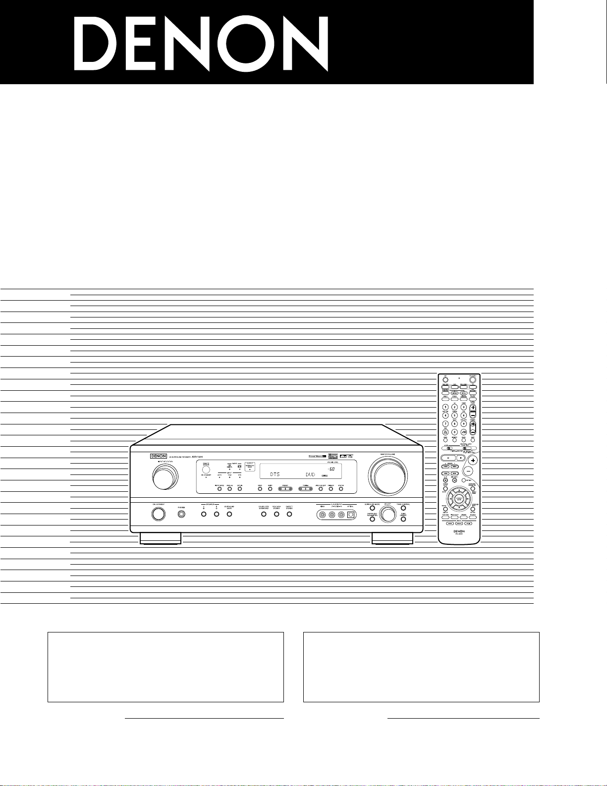
2
We greatly appreciate your purchase of this unit.
2
To be sure you take maximum advantage of all the
features this unit has to offer, read these instructions
carefully and use the set properly. Be sure to keep this
manual for future reference should any questions or
problems arise.
“SERIAL NO.
PLEASE RECORD UNIT SERIAL NUMBER ATTACHED TO
THE REAR OF THE CABINET FOR FUTURE REFERENCE”
“NO. DE SERIE
PRIERE DE NOTER LE NUMERO DE SERIE DE L’APPAREIL
INSCRIT A L’ARRIERE DU COFFRET DE FAÇON A POUVOIR
LE CONSULTER EN CAS DE PROBLEME.”
2
Nous vous remercions pour l’achat de cet appareil.
2
Pour être sûr de profiter au maximum de toutes les
caractéristiques qu’offre cet appareil, lire avec soin ces
instructions et bien utiliser l’appareil. Toujours
conserver ce mode d’emploi pour s’y référer
ultérieurement en cas de question ou de problème.
FOR ENGLISH READERS PAGE 2 ~ PAGE 62, 122 ~ 126 POUR LES LECTEURS FRANCAIS PAGE 2, 63 ~ PAGE 126
AV SURROUND RECEIVER
RÉCEPTEUR AUDIO-VIDÉO
AVR-1604/684
OPERATING INSTRUCTIONS
MODE D’EMPLOI
2
ENGLISH
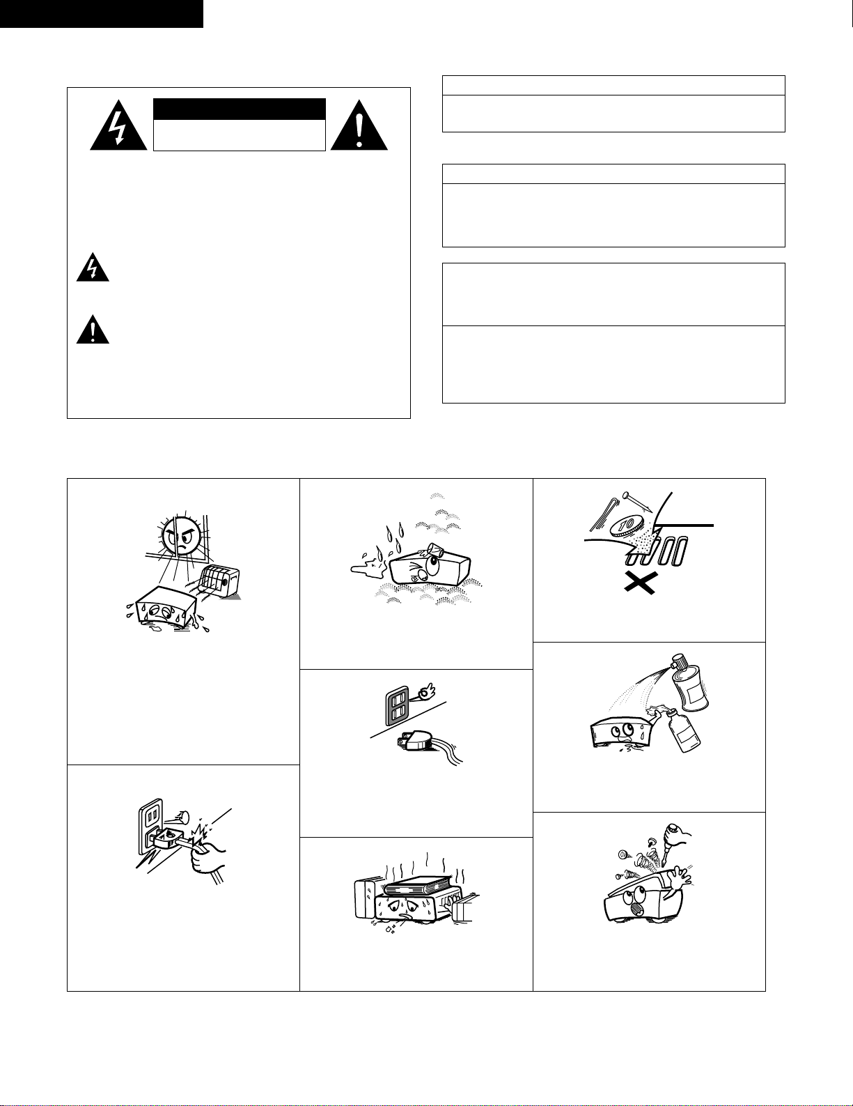
2 SAFETY PRECAUTIONS
2 NOTE ON USE / OBSERVATIONS RELATIVES A L’UTILISATION
• Avoid high temperatures.
Allow for sufficient heat dispersion when
installed on a rack.
• Eviter des températures élevées.
Tenir compte d’une dispersion de chaleur
suffisante lors de l’installation sur une étagère.
• Handle the power cord carefully.
Hold the plug when unplugging the cord.
• Manipuler le cordon d’alimentation avec
précaution.
Tenir la prise lors du débranchement du
cordon.
• Keep the set free from moisture, water, and
dust.
• Protéger l’appareil contre l’humidité, l’eau et la
poussière.
• Unplug the power cord when not using the set
for long periods of time.
• Débrancher le cordon d’alimentation lorsque
l’appareil n’est pas utilisé pendant de longues
périodes.
* (For sets with ventilation holes)
• Do not obstruct the ventilation holes.
• Ne pas obstruer les trous d’aération.
• Do not let foreign objects in the set.
• Ne pas laisser des objets étrangers dans
l’appareil.
• Do not let insecticides, benzene, and thinner
come in contact with the set.
• Ne pas mettre en contact des insecticides, du
benzène et un diluant avec l’appareil.
• Never disassemble or modify the set in any
way.
• Ne jamais démonter ou modifier l’appareil
d’une manière ou d’une autre.
CAUTION: TO REDUCE THE RISK OF ELECTRIC SHOCK,
DO NOT REMOVE COVER (OR BACK). NO
USER-SERVICEABLE PARTS INSIDE. REFER
SERVICING TO QUALIFIED SERVICE
PERSONNEL.
The lightning flash with arrowhead symbol, within an
equilateral triangle, is intended to alert the user to the
presence of uninsulated “dangerous voltage” within the
product’s enclosure that may be of sufficient magnitude to
constitute a risk of electric shock to persons.
The exclamation point within an equilateral triangle is intended
to alert the user to the presence of important operating and
maintenance (servicing) instructions in the literature
accompanying the appliance.
WARNING:
TO REDUCE THE RISK OF FIRE OR ELECTRIC
SHOCK, DO NOT EXPOSE THIS APPLIANCE
TO RAIN OR MOISTURE.
CAUTION
TO PREVENT ELECTRIC SHOCK, MATCH WIDE BLADE OF PLUG
TO WIDE SLOT, FULLY INSERT.
ATTENTION
POUR ÉVITER LES CHOCS ÉLECTRIQUES, INTERODUIRE LA
LAME LA PLUS LARGE DE LA FICHE DANS LA BORNE
CORRESPONDANTE DE LA PRISE ET POUSSER JUSQU’ AU
FOND.
This device complies with Part 15 of the FCC Rules. Operation is subject to
the following two conditions: (1) This device may not cause harmful
interference, and (2) this device must accept any interference received,
including interference that may cause undesired operation.
This Class B digital apparatus meets all requirements of the Canadian
Interference-Causing Equipment Regulations.
Cet appareil numérique de la classe B respecte toutes les exigences du
Règlement sur le matériel brouilleur du Canada.
FRANCAIS
•
FOR CANADA MODEL ONLY
•
POUR LES MODELE CANADIEN UNIQUEMENT
CAUTION
RISK OF ELECTRIC SHOCK
DO NOT OPEN

3
SAFETY INSTRUCTIONS
1. Read Instructions – All the safety and operating instructions
should be read before the product is operated.
2. Retain Instructions – The safety and operating instructions
should be retained for future reference.
3. Heed Warnings – All warnings on the product and in the
operating instructions should be adhered to.
4. Follow Instructions – All operating and use instructions should
be followed.
5. Cleaning – Unplug this product from the wall outlet before
cleaning. Do not use liquid cleaners or aerosol cleaners.
6. Attachments – Do not use attachments not recommended by
the product manufacturer as they may cause hazards.
7. Water and Moisture – Do not use this product near water – for
example, near a bath tub, wash bowl, kitchen sink, or laundry
tub; in a wet basement; or near a swimming pool; and the like.
8. Accessories – Do not place this product on an unstable cart,
stand, tripod, bracket, or table. The product may fall, causing
serious injury to a child or adult, and serious damage to the
product. Use only with a cart, stand, tripod, bracket, or table
recommended by the manufacturer, or sold with the product.
Any mounting of the product should follow the manufacturer’s
instructions, and should use a
mounting accessory
recommended by the
manufacturer.
9. A product and cart
combination should be
moved with care. Quick
stops, excessive force,
and uneven surfaces may
cause the product and cart
combination to overturn.
10. Ventilation – Slots and openings in the cabinet are provided for
ventilation and to ensure reliable operation of the product and to
protect it from overheating, and these openings must not be
blocked or covered. The openings should never be blocked by
placing the product on a bed, sofa, rug, or other similar surface.
This product should not be placed in a built-in installation such
as a bookcase or rack unless proper ventilation is provided or
the manufacturer’s instructions have been adhered to.
11. Power Sources – This product should be operated only from the
type of power source indicated on the marking label. If you are
not sure of the type of power supply to your home, consult your
product dealer or local power company. For products intended
to operate from battery power, or other sources, refer to the
operating instructions.
12. Grounding or Polarization – This product may be equipped with
a polarized alternating-current line plug (a plug having one blade
wider than the other). This plug will fit into the power outlet
only one way. This is a safety feature. If you are unable to
insert the plug fully into the outlet, try reversing the plug. If the
plug should still fail to fit, contact your electrician to replace your
obsolete outlet. Do not defeat the safety purpose of the
polarized plug.
13. Power-Cord Protection – Power-supply cords should be routed
so that they are not likely to be walked on or pinched by items
placed upon or against them, paying particular attention to
cords at plugs, convenience receptacles, and the point where
they exit from the product.
15. Outdoor Antenna Grounding – If an outside antenna or cable
system is connected to the product, be sure the antenna or
cable system is grounded so as to provide some protection
against voltage surges and built-up static charges. Article 810
of the National Electrical Code, ANSI/NFPA 70, provides
information with regard to proper grounding of the mast and
supporting structure, grounding of the lead-in wire to an
antenna discharge unit, size of grounding conductors, location
of antenna-discharge unit, connection to grounding electrodes,
and requirements for the grounding electrode. See Figure A.
16. Lightning – For added protection for this product during a
lightning storm, or when it is left unattended and unused for
long periods of time, unplug it from the wall outlet and
disconnect the antenna or cable system. This will prevent
damage to the product due to lightning and power-line surges.
17. Power Lines – An outside antenna system should not be
located in the vicinity of overhead power lines or other electric
light or power circuits, or where it can fall into such power lines
or circuits. When installing an outside antenna system,
extreme care should be taken to keep from touching such
power lines or circuits as contact with them might be fatal.
18. Overloading – Do not overload wall outlets, extension cords, or
integral convenience receptacles as this can result in a risk of
fire or electric shock.
19. Object and Liquid Entry – Never push objects of any kind into
this product through openings as they may touch dangerous
voltage points or short-out parts that could result in a fire or
electric shock. Never spill liquid of any kind on the product.
20.
Servicing – Do not attempt to service this product yourself as
opening or removing covers may expose you to dangerous
voltage or other hazards. Refer all servicing to qualified
service personnel.
21.
Damage Requiring Service – Unplug this product from the
wall outlet and refer servicing to qualified service
personnel
under the following conditions:
a) When the power-supply cord or plug is damaged,
b) If liquid has been spilled, or objects have fallen into the
product,
c) If the product has been exposed to rain or water,
d) If the product does not operate normally by following the
operating instructions. Adjust only those controls that are
covered by the operating instructions as an improper
adjustment of other controls may result in damage and will
often require extensive work by a qualified technician to
restore the product to its normal operation,
e) If the product has been dropped or damaged in any way, and
f) When the product exhibits a distinct change in performance
– this indicates a need for service.
22. Replacement Parts – When replacement parts are required, be
sure the service technician has used replacement parts
specified by the manufacturer or have the same characteristics
as the original part. Unauthorized substitutions may result in
fire, electric shock, or other hazards.
23. Safety Check – Upon completion of any service or repairs to this
product, ask the service technician to perform safety checks to
determine that the product is in proper operating condition.
24. Wall or Ceiling Mounting – The product should be mounted to a
wall or ceiling only as recommended by the manufacturer.
25. Heat – The product should be situated away from heat sources
such as radiators, heat registers, stoves, or other products
(including amplifiers) that produce heat.
FIGURE A
EXAMPLE OF ANTENNA GROUNDING
AS PER NATIONAL
ELECTRICAL CODE
ANTENNA
LEAD IN
WIRE
GROUND
CLAMP
ELECTRIC
SERVICE
EQUIPMENT
ANTENNA
DISCHARGE UNIT
(NEC SECTION 810-20)
GROUNDING CONDUCTORS
(NEC SECTION 810-21)
GROUND CLAMPS
POWER SERVICE GROUNDING
ELECTRODE SYSTEM
(NEC ART 250, PART H)
NEC — NATIONAL ELECTRICAL CODE
4
ENGLISH
2 INTRODUCTION
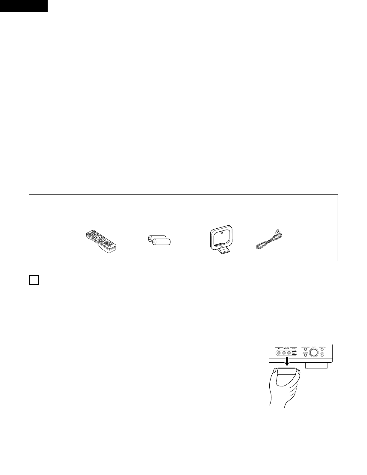
2 ACCESSORIES
Thank you for choosing the DENON A/V Surround receiver. This remarkable component has been engineered to provide superb surround sound
listening with home theater sources such as DVD, as well as providing outstanding high fidelity reproduction of your favorite music sources.
As this product is provided with an immense array of features, we recommend that before you begin hookup and operation that you review the
contents of this manual before proceeding.
TABLE OF CONTENTS
Check that the following parts are included in addition to the main unit:
1
BEFORE USING
Pay attention to the following before using this unit:
• Moving the set
T o prevent short circuits or damaged wires in the connection cords,
always unplug the power cord and disconnect the connection
cords between all other audio components when moving the set.
• Before turning the power operation switch on
Check once again that all connections are proper and that there are
not problems with the connection cords. Always set the power
operation switch to the standby position before connecting and
disconnecting connection cords.
• Store this instructions in a safe place.
After reading, store this instructions along with the warranty in a
safe place.
• Note that the illustrations in this instructions may differ from
the actual set for explanation purposes.
• V. AUX terminal
The AVR-1604/684’s front
panel is equipped with a V.
AUX terminal. Remove the
cap covering the terminal
when you want to use it.
z
Before Using ………………………………………………………………………………….4
x
Cautions on Installation……………………………………………………………………5
c
Cautions on Handling ………………………………………………………………………5
v
Features…………………………………………………………………………………………5
b
Part Names and Functions……………………………………………………………6, 7
n
Read this first…………………………………………………………………………………8
m
Setting up the Speaker Systems……………………………………………………….8
,
Connections……………………………………………………………………………..9~15
.
Using the Remote Control Unit……………………………………………………….16
⁄0
Setting up the System……………………………………………………………..17~26
⁄1
Remote Control Unit………………………………………………………………..27~31
⁄2
Operation ……………………………………………………………………………….32~36
⁄3
Surround…………………………………………………………………………………37~45
⁄4
DSP Surround Simulation………………………………………………………….46~50
⁄5
Listening to the Radio ……………………………………………………51~53
⁄6
Last Function Memory…………………………………………………………………..54
⁄7
Initialization of the Microprocessor.…………………………………………54
⁄8
Additional Information ………………………………………………………………55~60
⁄9
Troubleshooting…………………………………………………………………………….61
¤0
Specifications .…………………………………………………………………62
List of Preset Codes……………………………………………………………………122~126
q Operating instructions ………………………………………………………………….1
w Warranty …………………………………………………………………………………….1
e Service station list………………………………………………………………………..1
r Remote control unit (RC-941)………………………………………………………..1
t R6P/AA batteries …………………………………………………………………………2
y AM loop antenna …………………………………………………………………………1
u FM indoor antenna……………………………………………………………………….1
5
ENGLISH
3
CAUTIONS ON HANDLING
4
FEATURES
• Switching the input function when input jacks are not
connected
A clicking noise may be produced if the input function is switched
when nothing is connected to the input jacks. If this happens,
either turn down the MASTER VOLUME control or connect
components to the input jacks.
• Muting of PRE OUT jack, HEADPHONE jack and SPEAKER
terminals
The PRE OUT jack, HEADPHONE jack and SPEAKER terminals
include a muting circuit. Because of this, the output signals are
greatly reduced for several seconds after the power operation
switch is turned on or input function, surround mode or any other
set-up is changed.
If the volume is turned up during this time, the output will be very
high after the muting circuit stops functioning. Always wait until
the muting circuit turns off before adjusting the volume.
• Whenever the power operation switch is in the STANDBY
state, the apparatus is still connected on some AC line
voltages.
Please be sure to unplug the cord when you leave home for,
say, a vacation.
1. Dolby Digital EX decoder system
Dolby Digital EX is a 6.1-channel surround format proposed by
Dolby Laboratories that allows users to enjoy in their homes the
“DOLBY DIGITAL SURROUND EX” audio format jointly
developed by Dolby Laboratories and Lucas Films and first used
for the movie “Star Wars Episode 1 – Phantom Menace”.
The 6.1 channels of sound, including surround back channels,
provide improved sound positioning and expression of space.
2. DTS-ES Extended Surround and DTS Neo:6
The AVR-1604/684 is compatible with DTS-ES Extended Surround, a
new multi-channel format developed by Digital Theater Systems Inc.
The AVR-1604/684 is also compatible with DTS Neo:6, a surround
mode allowing 6.1-channel playback of regular stereo sources.
3. Dolby Pro Logic II decoder
Dolby Pro Logic II is a new format for playing multichannel audio
signals that offers improvements over conventional Dolby Pro
Logic. It can be used to decode not only sources recorded in
Dolby Surround but also regular stereo sources into five channels
(front left/right, center and surround left/right). In addition, various
parameters can be set according to the type of source and the
contents, so you can adjust the sound field with greater precision.
4. Dolby Digital decoder
Using advanced digital processing algorithms, Dolby Digital
provides up to 5.1 channels of wide-range, high fidelity surround
sound. Dolby Digital is the default digital audio delivery system for
DVD and North American DTV.
5. DTS (Digital Theater Systems)
DTS provides up to 5.1 channels of wide-range, high fidelity
surround sound, from sources such as laser disc, DVD and
specially-encoded music discs.
6. Auto Surround Mode
This function stores the surround mode last used for an input
signal in the memory and automatically sets that surround mode
the next time that signal is input.
7. 6CH EXT. IN jacks
This unit is equipped with 6CH EXT. IN jacks for use with audio
formats of the future.
8. High performance DSP simulates 7 sound fields
Playback is possible in 7 surround modes: 5/6-channel Stereo,
Mono Movie, Rock Arena, Jazz Club, Video Game, Matrix and
Virtual. You can enjoy a variety of sound effects for different movie
scenes and program sources even with stereo sources not in
Dolby Surround.
9. Personal Memory Plus function
Personal Memory Plus is an advanced version of Personal
Memory. With Personal Memory Plus, the set automatically
memorizes the surround mode, channel volume, surround
parameters, etc., for each of the separate input sources.
2
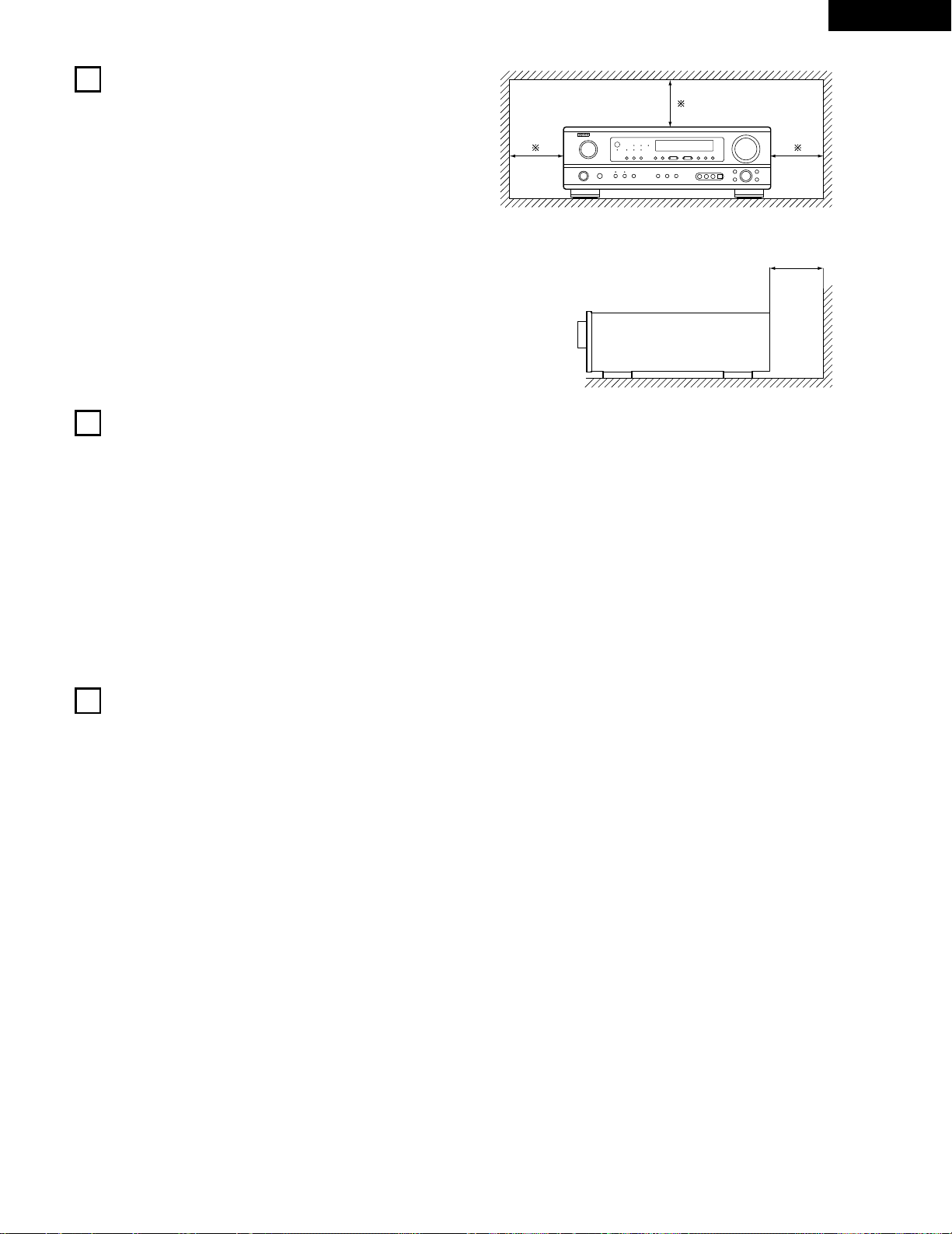
CAUTIONS ON INSTALLATION
Noise or disturbance of the picture may be generated if this unit or
any other electronic equipment using microprocessors is used near a
tuner or TV.
If this happens, take the following steps:
• Install this unit as far as possible from the tuner or TV.
• Set the antenna wires from the tuner or TV away from this unit’s
power cord and input/output connection cords.
• Noise or disturbance tends to occur particularly when using indoor
antennas or 300 Ω/ohms feeder wires. We recommend using
outdoor antennas and 75 Ω/ohms coaxial cables.
For heat dispersal, leave at least 0.3 ft (10 cm) of space between
the top, back and sides of this unit and the wall or other
components.
0.3 ft (10 cm) or more
wall
0.3 ft (10 cm) or more
6
ENGLISH
5
PART NAMES AND FUNCTIONS
Front Panel
• For details on the functions of these parts, refer to the pages given in parentheses ( ).
q wue ir
y
o!4t !1
@1@2
@3@4@5@6@7@8@9
!2 !3 !5 !6 !7!0
!8@0 !9#0
q
Power operation switch ……………………………………….(18, 32, 51)
w
Headphones jack (PHONES)…………………………………………….(35)
e
INPUT MODE button……………………………………………(33, 36, 43)
r
SPEAKER A/B buttons……………………………………………….(32, 54)
t
SURROUND BACK button ………………………………………………(43)
y
ANALOG button ……………………………………………………….(33, 36)
u
EXT. IN button ………………………………………………………….(33, 36)
i
DOLBY/DTS SURROUND button…………………………..(37, 39, 43)
o
5CH/6CH STEREO button ………………………………………….(46, 49)
!0
DIRECT/STEREO button………………………………………………….(46)
!1
TUNING D (up) / H (down) buttons…………………………………..(52)
!2
VIDEO SELECT button ……………………………………………………(35)
!3
V. AUX terminals…………………………………………………………(4, 11)
!4
SURROUND MODE button………………………………………..(34, 49)
!5
SURROUND PARAMETER button……………………………….(39, 47)
!6
SELECT knob………………………………………………………(34, 39, 49)
!7
TONE DEFEAT button…………………………………………………….(34)
!8
TONE CONTROL button………………………………………………….(34)
!9
MASTER VOLUME control ………………………………………………(34)
@0
STATUS button ………………………………………………………………(35)
@1
DIMMER button …………………………………………………………….(35)
@2
Master volume indicator (VOLUME LEVEL) ……………………….(34)
@3
Display
@4
Preset station select buttons ……………………………………..(51, 53)
@5
BAND button …………………………………………………………………(52)
@6
SIGNAL indicators…………………………………………………………..(34)
@7
INPUT mode indicators……………………………………………………(34)
@8
Remote control sensor (REMOTE SENSOR) ……………………..(16)
@9
Power operation indicator (ON/STANDBY)
#0
INPUT SELECTOR knob………………………………………………….(33)
NOTE:
• The shaded buttons do not function with the AVR-1604/684.
(Nothing happens when they are pressed.)
7
ENGLISH
Remote control unit
• For details on the functions of these parts, refer to the pages given in parentheses ( ).
SURROUND
buttons……………………………..(34, 37, 47)
Cursor
buttons………………………..(17, 29, 37, 47)
STATUS/DISPLAY button………….(29, 35)
Test tone button……………………………(37)
Remote control signal
transmitter …………………………………..(16)
Master volume control
buttons………………………………………..(34)
POWER buttons…………..(18, 28~30, 32)
MUTING button ……………………………(35)
Mode selector switches..(17, 27~29, 31)
Tuner system/
System buttons ……………(27, 30, 52, 53)
SYSTEM SET UP/
SETUP button……………………(17, 26, 29)
INPUT MODE selector
buttons…………………………………..(33, 36)
Input source selector
buttons ……………………….(28~31, 33, 39)
SURROUND PARAMETER
button…………………………………….(29, 39)
CH SELECT (channel select)/
ENTER button ………………(17, 29, 38, 40)
SURROUND BACK/
RETURN button ………………………(29, 43)
SPEAKER select button…………………(32)
DIMMER button……………………………(35)VIDEO SELECT button…………………..(35)
System buttons …………………(27, 29, 30)
LED (indicator) ………………………..(28, 31)
8
ENGLISH
6
READ THIS FIRST
This AV Surround Receiver must be setup before use. Following these steps.
7
SETTING UP THE SPEAKER SYSTEMS
Step 3 (page 17 to 26)
Finally, setting up the system.
Step 2 (page 16)
Next, insert the batteries into the remote control unit.
Step 1 (page 8 to 15)
Choose the best location to setup the Speakers and connecting the components.
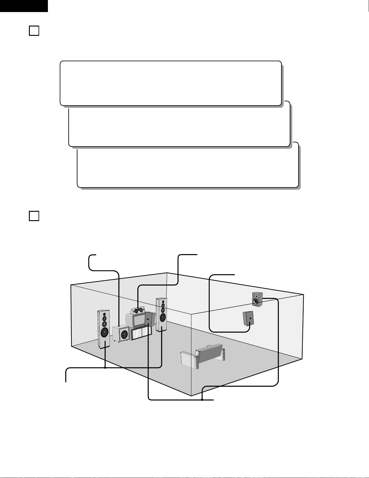
2 Speaker system layout
Basic system layout
• The following is an example of the basic layout for a system consisting of seven speaker systems and a television monitor:
Subwoofer Center speaker system
Surround speaker systems
Surround back speaker system
Front speaker systems
Set these at the sides of the TV or screen with
their front surfaces as flush with the front of the
screen as possible.
9
ENGLISH
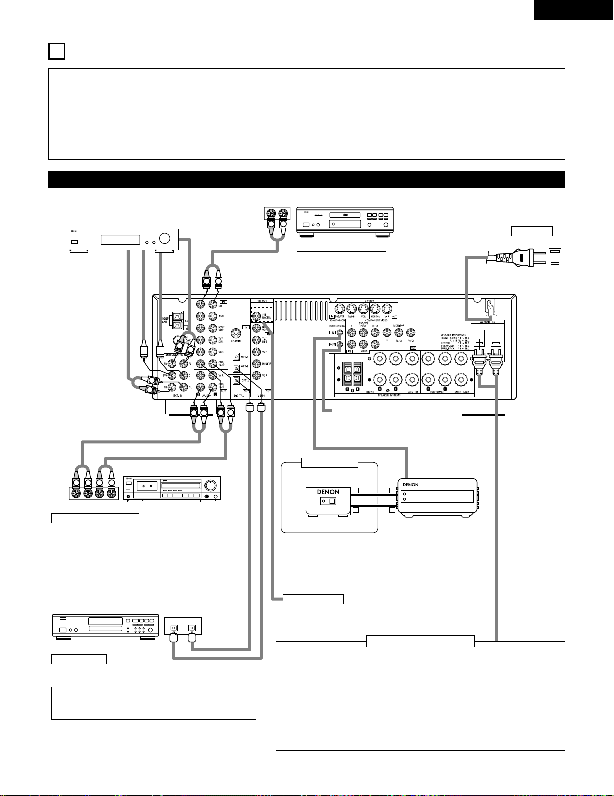
8
CONNECTIONS
• Do not plug in the power cord until all connections have been
completed.
• Be sure to connect the left and right channels properly (left with
left, right with right).
• Insert the plugs securely. Incomplete connections will result in
the generation of noise.
• Use the AC OUTLETS for audio equipment only. Do not
use them for hair driers, etc.
• Note that binding pin plug cords together with power cords or
placing them near a power transformer will result in generating
hum or other noise.
• Noise or humming may be generated if a connected audio
equipment is used independently without turning the power
of this unit on. If this happens, turn on the power of the this
unit.
Connecting the audio components
LINE OUT
SURROUND
SUB WOOFER
CENTER
FRONT
LINE OUT
LINE OUT
LINE IN
R
OUTPUTINPUT
LRL
R
OUTPUT
L
R
L
R
L
R
L
L
R
L
R
R
L
R
L
L
R
DIGITAL AUDIODIGITAL AUDIO
INPUTOUTPUT
OPTICAL
B
++
INPUT
OUTPUT
AUX OUT
Connecting a CD player
Connect the CD player’s analog output jacks
(ANALOG OUTPUT) to this unit’s CD jacks using
pin plug cords.
Decoders with 6-channel
analog outputs, etc.
DIGITAL jacks
Use these for connections to audio equipment with digital output.
Refer to Page 25 for instructions on setting this terminal.
Connecting the AC OUTLETS
AC OUTLETS
• SWITCHED
(total capacity – 120 W (1 A.))
The power to these outlets is turned on and off in conjunction with the POWER switch
on the main unit, and when the power is switched between on and standby from the
remote control unit.
No power is supplied from these outlets when this unit’s power is at standby. Never
connect equipment whose total capacity is above 120 W (1 A.)
NOTE:
Only use the AC OUTLETS for audio equipment. Never use them for hair driers, TVs or
other electrical appliances.
AC CORD
AC 120V, 60Hz
Connect the internal amplifier’s subwoofer to the subwoofer
terminal. (Refer to page 14.)
Connecting a tape deck
Connections for recording:
Connect the tape deck’s recording input jacks (LINE IN or
REC) to this unit’s tape recording (OUT) jacks using pin plug
cords.
Connections for playback:
Connect the tape deck’s playback output jacks (LINE OUT or
PB) to this unit’s tape playback (IN) jacks using pin plug cords.
CD player
Tape deck or CD recorder
• Use 75 Ω/ohms cable pin cords (sold separately) for coaxial
connections.
• Use optical cables (sold separately) for optical connections.
Subwoofer jack
CD recorder, MD recorder or other component
equipped with digital output jacks.
• When a sold separately room-to-room remote control unit
(DENON RC-616, 617 or 618) is wired and connected between
the MAIN ROOM and ANOTHER ROOM, the remotecontrollable devices in the main room can be controlled from
ANOTHER ROOM using the remote control unit.
Another room
RC-617 (Sold Separately)
Infrared sensor
RC-616
(Sold Separately)
Infrared retransmitter
Extension jacks for future use.
10
ENGLISH
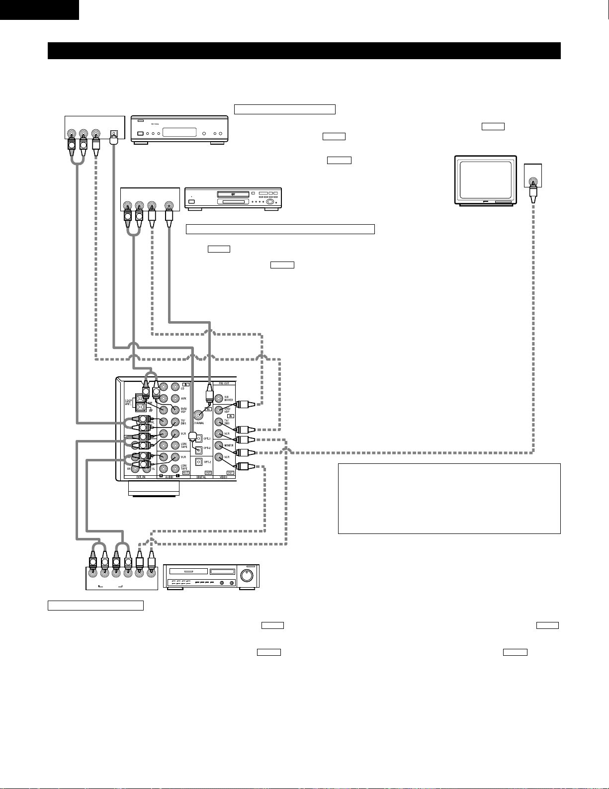
Connecting the video equipments
To connect the video signal, connect using a 75 Ω/ohms video signal cable cord. Using an improper cable can result in a drop in sound quality.
IN
VIDEO
R
L
R
L
R
L
L
R
R OUT IN
AUDIO
VIDEO
OUT IN
LRL
R
L
R
L
R OUT
VIDEO
OUT
L
AUDIO
OUT
COAXIAL
DIGITAL
L
R
R OUT
VIDEO
OPTICAL
OUT
L
AUDIO
OUT
DIGITAL
L
R
B
B
TV or DBS tuner
DVD player or VDP
Monitor TV
Connecting a TV/DBS tuner
TV/DBS
• Connect the TV’s or DBS tuner’s video output jack
(VIDEO OUTPUT) to the (yellow) TV/DBS IN
jack using a 75 Ω/ohms video coaxial pin plug cord.
• Connect the TV’s or DBS tuner’s audio output jacks
(AUDIO OUTPUT) to the TV/DBS IN jacks
using pin plug cords.
AUDIO
VIDEO
Connecting a DVD player or a video disc player (VDP)
• Connect the DVD player’s (video disc player’s) video output jack (VIDEO OUTPUT) to
the (yellow) DVD/VDP IN jack using a 75 Ω/ohms video coaxial pin plug cord.
• Connect the DVD player’s (video disc player’s) analog audio output jacks (ANALOG
AUDIO OUTPUT) to the DVD/VDP IN jacks using pin plug cords.
• For better sound quality, we recommend using the DVD player with digital rather than
analog connections.
DVD and VDP players can also be connected to the VCR terminals.
AUDIO
VIDEO
MONITOR OUT
• Connect the TV’s video input jack (VIDEO
INPUT) to the MONITOR OUT
jack using a 75 Ω/ohms video coaxial pin
plug cord.
VIDEO
NOTE:
Connection of the video disc Player Equipped with Dolby Digital RF
Output Jack.
• Please use a commercially available adaptor when connecting the
Dolby Digital RF output jack of the video disc player to the digital
input jack.
Please refer to the instruction manual of the adapter when making
connections.
Video deck
Video input/output connections:
• Connect the video deck’s video output jack (VIDEO OUT) to the (yellow) VCR IN jack, and the video deck’s video input jack (VIDEO IN) to the
(yellow) VCR OUT jack using 75 Ω/ohms video coaxial pin plug cords.
Connecting the audio output jacks:
• Connect the video deck’s audio output jacks (AUDIO OUT) to the VCR IN jacks, and the video deck’s audio input jacks (AUDIO IN) to the VCR OUT
jacks using pin plug cords.
AUDIOAUDIO
VIDEOVIDEO
Connecting a video decks
VIDEO OUT
VIDEO IN
VIDEO IN
AUDIO OUT
VIDEO OUT
VIDEO OUT
AUDIO OUT
AUDIO OUT
AUDIO IN
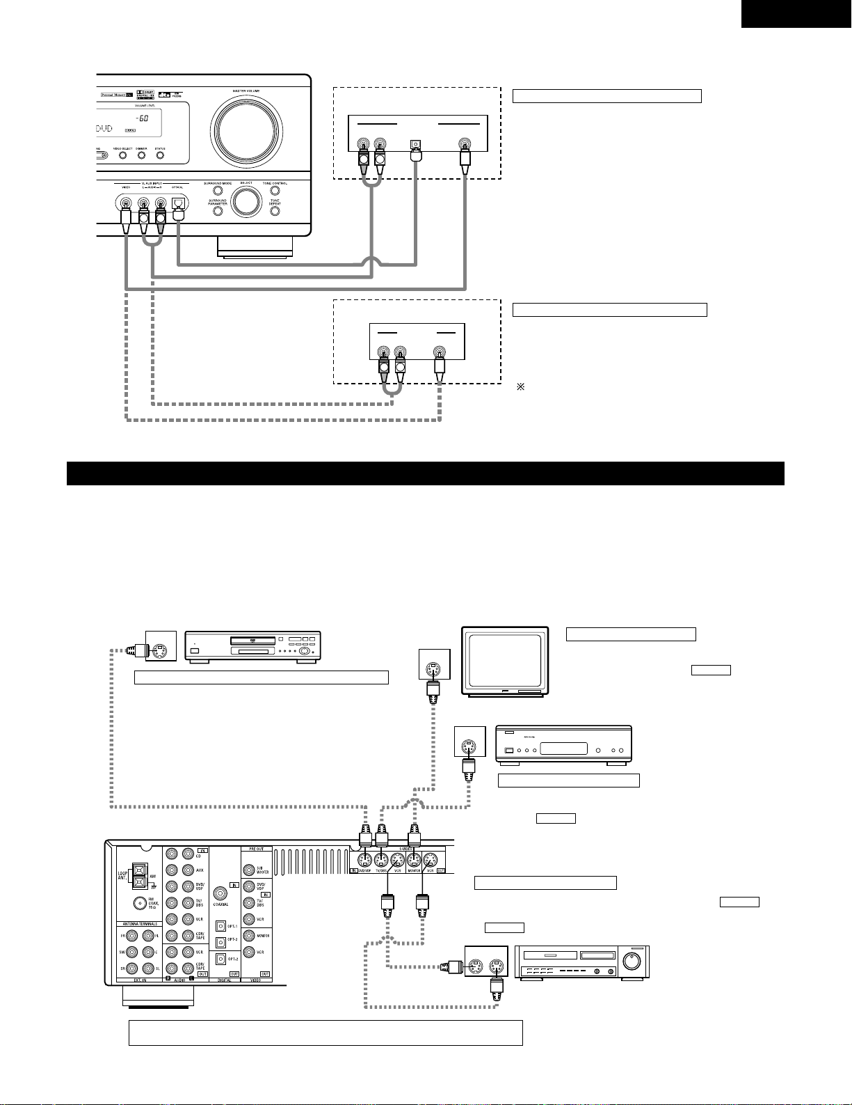
11
ENGLISH
Connecting a video component equipped with S-video jacks
• When marking connections, also refer to the operating instructions of the other components.
• A note on the S input jacks
The input selectors for the S inputs and pin jack inputs work in conjunction with each other.
• Precaution when using S-jacks
This unit’s S-jacks (input and output) and video pin jacks (input and output) have independent circuit structures, so that video signals input from
the S-jacks are only output from the S-jack outputs and video signals input from the pin jacks are only output from the pin jack outputs.
When connecting this unit with equipment that is equipped with S-jacks, keep the above point in mind and make connections according to the
equipment’s instruction manuals.
IN
S-VIDEO
OUT
S-VIDEO
OUT
S-VIDEO
OUT IN
S-VIDEO
VIDEO IN
VIDEO OUT
VIDEO IN
VIDEO OUT
VIDEO OUT
B
B
DVD player, VDP, etc.
Connecting a DVD player or video disc player (VDP)
DVD/VDP
• Connect the DVD player’s or video disc player’s SVideo output jack to the S-VIDEO DVD/VDP IN jack
using an S-Video connection cord.
Connecting a monitor TV
MONITOR OUT
• Connect the TV’s or DBS tuner’s S video input
(S-VIDEO INPUT) to the MONITOR
OUT jack using a S jack connection cord.
S-VIDEO
Monitor TV
Connecting a TV/DBS tuner
• Connect the TV’s or DBS tuner’s S
video output jack (S-VIDEO OUTPUT)
to the TV/DBS IN jack using
an S jack connection cord.
S-VIDEO
TV or satellite broadcast tuner
Video deck
Connecting the video decks
• Connect the video deck’s S output jack (S-OUT) to the
VCR IN jack and the video deck’s S input jack (S-IN) to the
VCR OUT jack using S jack connection cords.
S-VIDEO
S-VIDEO
Connect the components’ audio inputs and outputs as described on page 10.
R VIDEO OUTOPTICALL
R VIDEO OUTL
OUTPUT
OUTPUT
LINE OUT
DIGITAL OUT
VIDEO OUT
VIDEO OUT
LINE OUT
L
R
L
R
L
R
Connecting a Video game equipment
• Connect the Video game equipment’s output jacks to this
unit’s V. AUX INPUT jacks.
Video game
Video camera
Connecting a Video camera equipment
• Connect the video camera equipment’s output jacks to this
unit’s V. AUX INPUT jacks.
The V. AUX terminal is covered with a cap. Remove this
cap in order to use the terminal. (See page 4 for instructions
on removing the cap.)
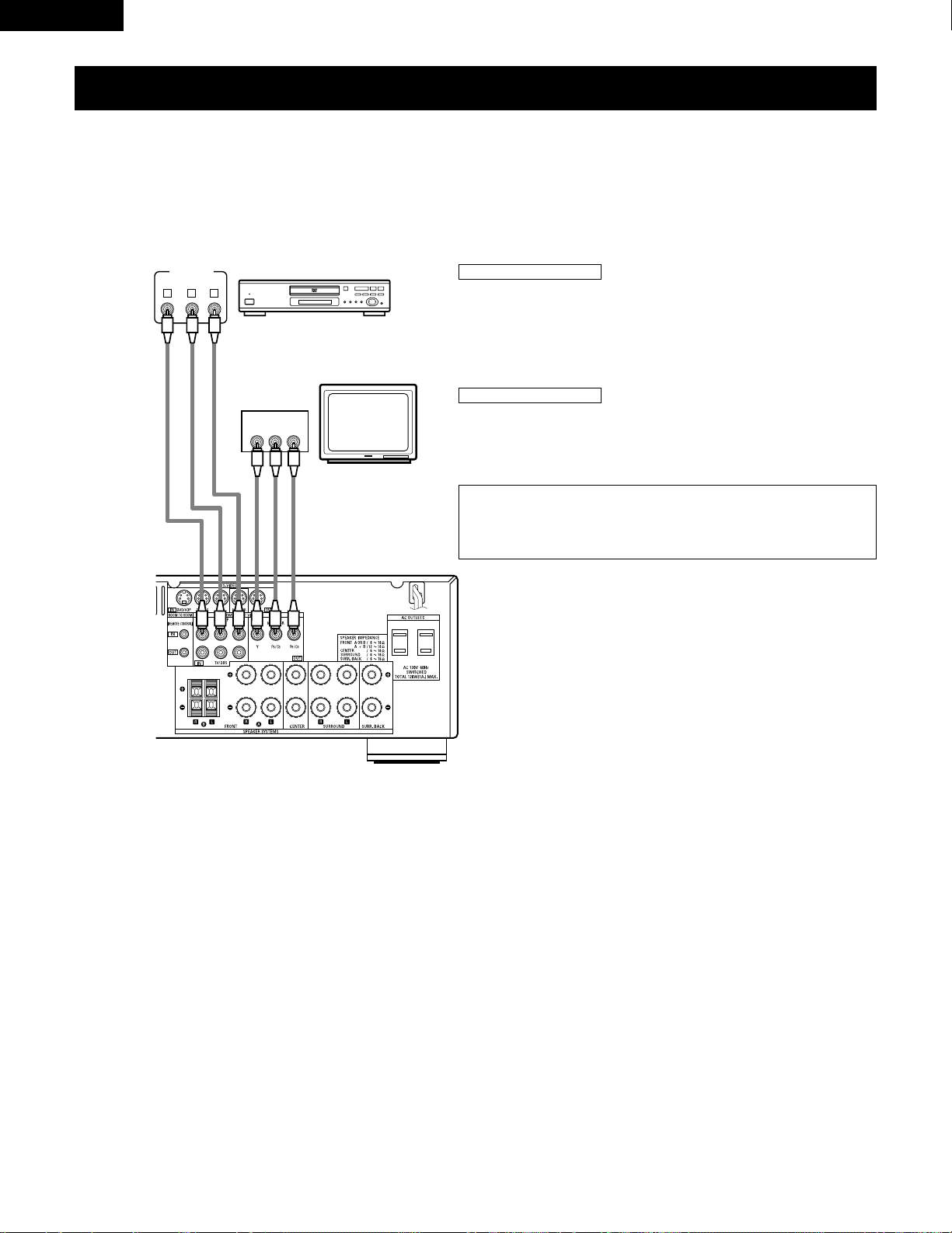
VIDEO OUT
Y
CRCB
COMPONENT
YCRCB
VIDEO IN
COMPONENT
B
Connecting a Video Component Equipped with Color Difference (Component — Y, PR/CR,
P
B/CB
) Video Jacks (DVD Player)
• When making connections, also refer to the operating instructions of the other components.
• The signals input to the color difference (component) video jacks are not output from the VIDEO output jack (yellow) or the S-Video output jack.
In addition, the video signals input to the VIDEO input (yellow) and S-Video input jacks are not output to the color difference (component) video
jacks.
• Some video sources with component video outputs are labeled Y, C
B, CR, or Y, Pb, Pr, or Y, R-Y, B-Y. These terms all refer to component video
color difference output.
DVD player
Connecting a DVD player
DVD IN jacks
• Connect the DVD player’s color difference (component) video output jacks
(COMPONENT VIDEO OUTPUT) to the COMPONENT DVD IN jack using 75 Ω/ohms
coaxial video pin-plug cords.
• In the same way, another video source with component video outputs such as a
TV/DBS tuner, etc., can be connected to the TV/DBS color difference (component)
video jacks.
Monitor TV
Connecting a monitor TV
MONITOR OUT jack
• Connect the TV’s color difference (component) video input jacks (COMPONENT
VIDEO INPUT) to the COMPONENT MONITOR OUT jack using 75 Ω/ohms coaxial
video pin-plug cords.
• The color difference input jacks may be indicated differently on some
TVs, monitors or video components (“C
R, CB
and Y”, “R-Y, B-Y and Y”,
“Pr, Pb and Y”, etc.). For details, carefully read the operating
instructions included with the TV or other component.
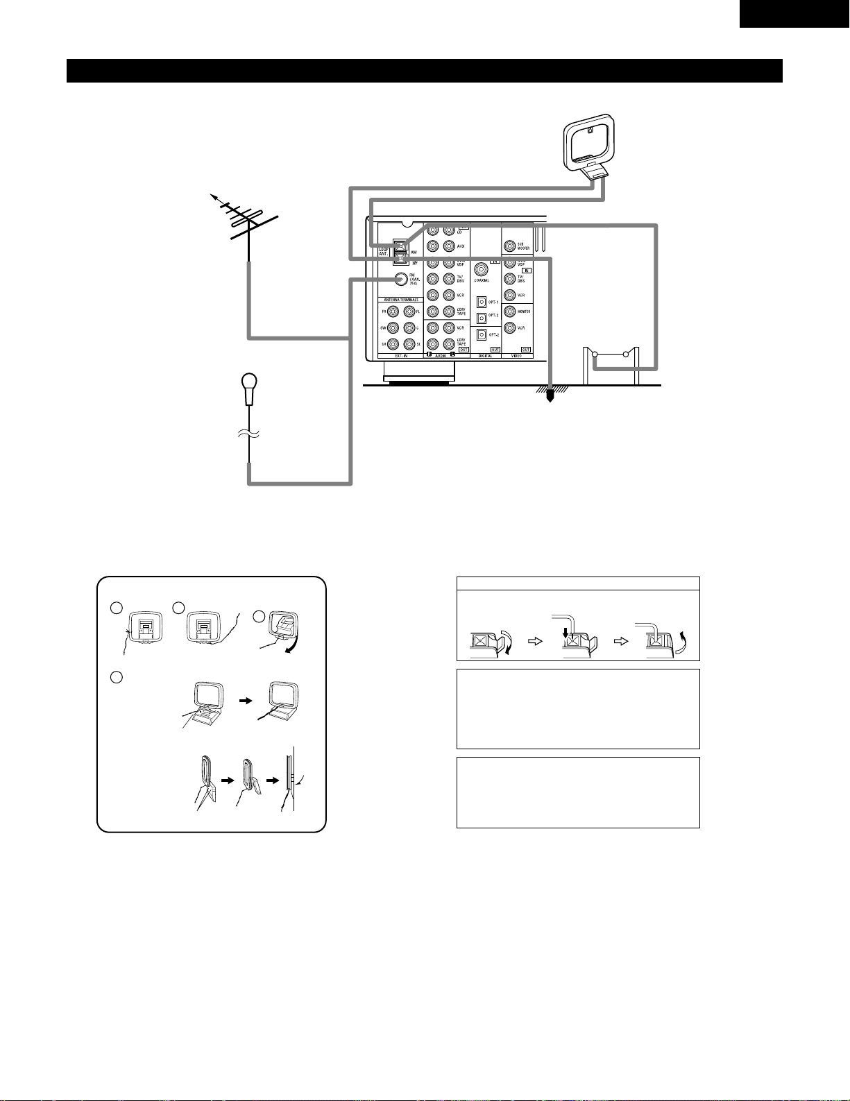
Connecting the antenna terminals
DIRECTION OF
BROADCASTING
STATION
AM LOOP
ANTENNA
(An Accessory)
FM ANTENNA
GROUND
AM OUTDOOR
ANTENNA
FM INDOOR ANTENNA
(An Accessory)
75 Ω/ohms
COAXIAL
CABLE
AM loop antenna assembly
Connect to the AM
antenna terminals.
Bend in the reverse
direction.
Remove the vinyl tie
and take out the
connection line.
a. With the antenna
on top any stable
surface.
b. With the antenna
attached to a
wall.
Mount
Installation hole
Mount on wall, etc.
Connection of AM antennas
1. Push the lever. 2. Insert the
conductor.
3. Return the lever.
Note to CATV system installer:
This reminder is provided to call the CATV system installer’s
attention to Article 820-40 of the NEC which provides
guidelines for proper grounding and, in particular, specifies
that the cable ground shall be connected to the grounding
system of the building, as close to the point of cable entry as
practical.
Notes:
• Do not connect two FM antennas simultaneously.
• Even if an external AM antenna is used, do not disconnect
the AM loop antenna.
• Make sure AM loop antenna lead terminals do not touch
metal parts of the panel.
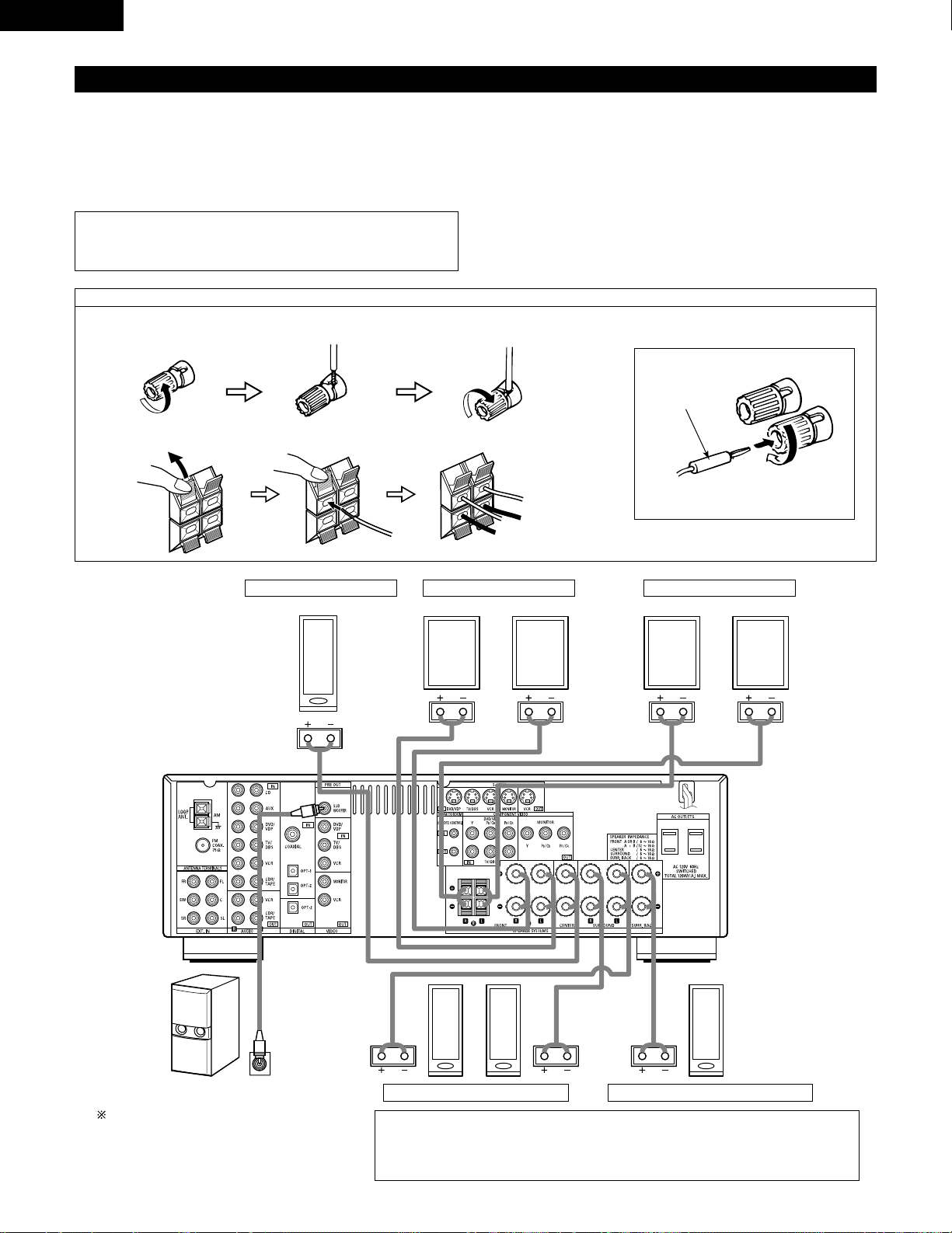
14
ENGLISH
Speaker system connections
• Connect the speaker terminals with the speakers making sure that like
polarities are matched (< with <, > with >). Mismatching of polarities will
result in weak central sound, unclear orientation of the various instruments,
and the sense of direction of the stereo being impaired.
• When making connections, take care that none of the individual conductors
of the speaker cord come in contact with adjacent terminals, with other
speaker cord conductors, or with the rear panel.
Speaker Impedance
• When speaker systems A and B are use separately, speakers with an
impedance of 6 to 16 Ω/ohms can be connected for use as front speakers.
• Be careful when using two pairs of front speakers (A + B) at the same time,
since use of speakers with an impedance of 12 to 16 Ω/ohms.
• Speakers with an impedance of 6 to 16 Ω/ohms can be connected for use
as center and surround and surround back speakers.
• The protector circuit may be activated if the set is played for long periods of
time at high volumes when speakers with an impedance lower than the
specified impedance are connected.
NOTE:
NEVER touch the speaker terminals when the power is on.
Doing so could result in electric shocks.
Connecting the speaker cords
1. Loosen by turning
counterclockwise.
2. Insert the cord. 3. Tighten by turning
clockwise.
Connecting banana plugs
Turn clockwise to tighten, then insert the
banana plug.
banana plug
1. Push the lever. 2. Insert the cord. 3. Return the lever.
Connection jack for subwoofer with built-in amplifier
(super woofer), etc.
To achieve Dolby Digital playback effect, use a unit
that can sufficiently reproduce frequencies of
under 80 Hz.
SURROUND SPEAKER SYSTEMS
CENTER SPEAKER SYSTEM FRONT SPEAKER SYSTEMS
• Precautions when connecting speakers
If a speaker is placed near a TV or video monitor, the colors on the screen may be disturbed by
the speaker’s magnetism. If this should happen, move the speaker away to a position where
it does not have this effect.
System B
FRONT SPEAKER SYSTEMS
System A
SURROUND BACK SPEAKER SYSTEM
15
ENGLISH
Protector circuit
• This unit is equipped with a high-speed protection circuit. The purpose of this circuit is to protect the speakers under
circumstances such as when the output of the power amplifier is inadvertently short-circuited and a large current flows,
when the temperature surrounding the unit becomes unusually high, or when the unit is used at high output over a long
period which results in an extreme temperature rise.
When the protection circuit is activated, the speaker output is cut off and the power supply indicator LED flashes. Should
this occur , please follow these steps: be sure to switch off the power of this unit, check whether there are any faults with
the wiring of the speaker cables or input cables, and wait for the unit to cool down if it is very hot. Improve the ventilation
condition around the unit and switch the power back on.
If the protection circuit is activated again even though there are no problems with the wiring or the ventilation around the
unit, switch off the power and contact a DENON service center.
Note on speaker impedance
• The protector circuit may be activated if the set is played for long periods of time at high volumes when speakers with
an impedance lower than the specified impedance (for example speakers with an impedance of lower than 4 Ω/ohms)
are connected. If the protector circuit is activated, the speaker output is cut off. Turn off the set’s power, wait for the set
to cool down, improve the ventilation around the set, then turn the power back on.
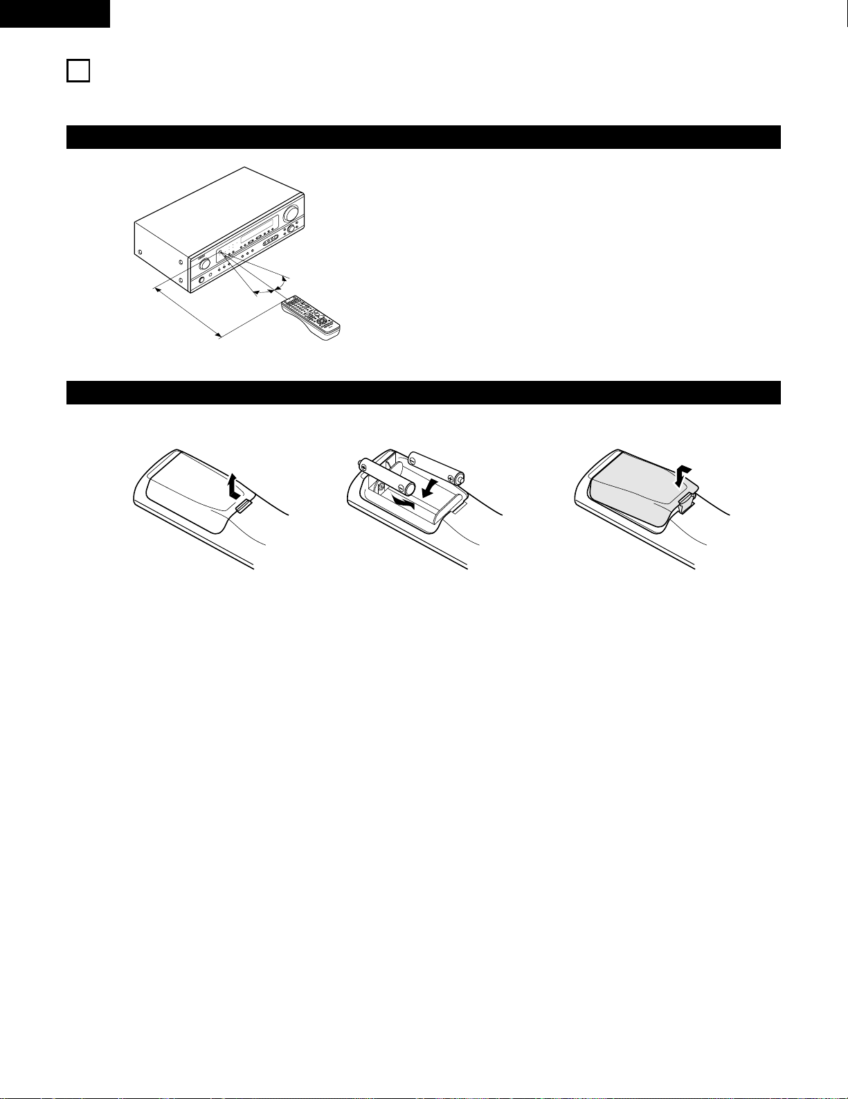
16
ENGLISH
9
USING THE REMOTE CONTROL UNIT
Following the procedure outlined below, insert the batteries before using the remote control unit.
Range of operation of the remote control unit
Inserting the batteries
Point the remote control unit at the remote control sensor as shown
on the diagram at the left.
NOTES:
• The remote control unit can be used from a straight distance of
approximately 23 feet/7 meters, but this distance will shorten or
operation will become difficult if there are obstacles between the
remote control unit and the remote control sensor, if the remote
control sensor is exposed to direct sunlight or other strong light, or
if operated from an angle.
• Neon signs or other devices emitting pulse-type noise nearby may
result in malfunction, so keep the set as far away from such
devices as possible.
Approx. 23 feet/7 m
30°
30°
w Insert the R6P/AA batteries properly, as
shown on the diagram.
q Press as shown by the arrow and slide
off.
e Close the lid.
NOTES:
• Use only R6P/AA batteries for replacement.
• Be sure the polarities are correct. (See the illustration inside the battery compartment.)
• Remove the batteries if the remote control transmitter will not be used for an extended period of time.
• If batteries leak, dispose of them immediately. Avoid touching the leaked material or letting it come in contact with clothing, etc. Clean the
battery compartment thoroughly before installing new batteries.
• Have replacement batteries on hand so that the old batteries can be replaced as quickly as possible when the time comes.
• Even if less than a year has passed, replace the batteries with new ones if the set does not operate even when the remote control unit is
operated nearby the set. (The included battery is only for verifying operation. Replace it with a new battery as soon as possible.)
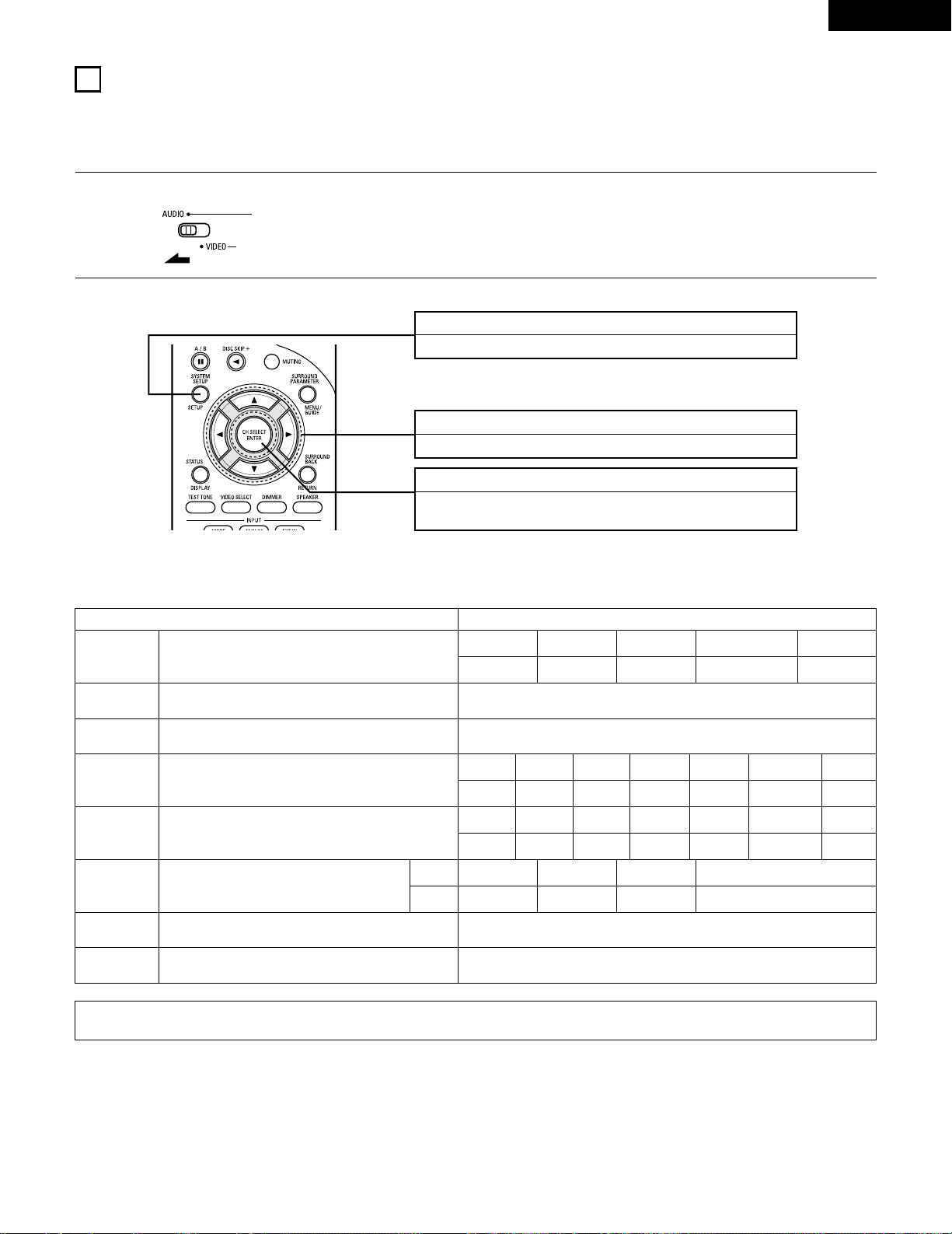
17
ENGLISH
10
SETTING UP THE SYSTEM
• Once all connections with other A V components have been completed as described in “CONNECTIONS” (see pages 9 to 15), make the various
settings described below on the display.
These settings are required to set up the listening room’s AV system centered around the this unit.
SYSTEM SETUP button
Press this to display the system setup on the display.
CURSOR buttons (•, ª, 0, 1)
Press this change what appears on the display.
ENTER button
Press this to switch the display.
Also use this button to complete the setting.
• System setup items and default values (set upon shipment from the factory)
System setup Default settings
Speaker
Configuration
Subwoofer Mode
Digital In
Assignment
Input the combination of speakers in your system and their
corresponding sizes (SMALL for regular speakers, LARGE for full-size,
full-range) to automatically set the composition of the signals output
from the speakers and the frequency response.
This assigns the digital input jacks for the different input
sources.
Input
source
Digital
Inputs
Front Sp.
Large
Center Sp. Surround Sp. Subwoofer
Small Small Yes
CD DVD/VDP
COAXIAL OPTICAL 1
Delay Time
This parameter is for optimizing the timing with which the audio
signals are produced from the speakers and subwoofer according to
the listening position.
1
Set the slide switch to “AUDIO”.
2
Use the following buttons to set up the system:
This selects the subwoofer speaker for playing deep bass signals. Subwoofer mode = Normal
NOTE:
• The system setup is not displayed when “HEADPHONE ONLY” is selected.
Crossover
Frequency
Set the frequency (Hz) below which the bass sound of the various
speakers is to be output from the subwoofer.
80 Hz
Auto Surround
Mode
Auto surround mode function setting. Auto Surround Mode = ON
Ext. In SW Level Set the Ext. In Subwoofer channel playback level. Ext. In SW Level = +15 dB
TV/DBS
OPTICAL 2
Surround back Sp.
Small
Front L Center Surround Back
12 ft 12 ft 10 ft
Subwoofer
12 ft
Front R
12 ft
Surround L
10 ft
Surround R
10 ft
Front L Front R Center
0 dB 0 dB 0 dB
Test Tone
This adjusts the volume of the signals output from the speakers and
subwoofer for the different channels in order to obtain optimum
effects.
Surround L
0 dB
Surround R
0 dB
Surround Back
0 dB
Subwoofer
0 dB
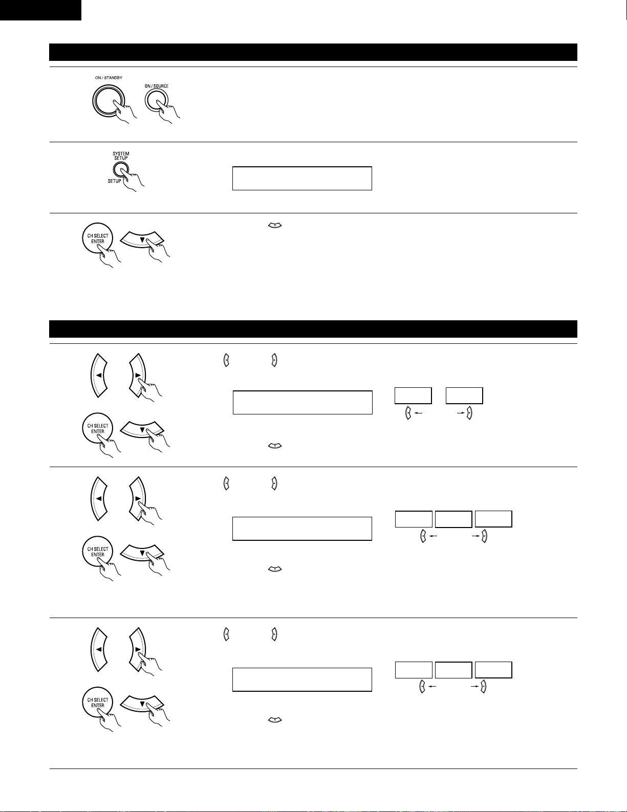
18
ENGLISH
Before setting up the system
1
2
Press the SYSTEM SETUP button to enter the setting.
Check that all the components are correct, then press the POWER operation switch on the main unit or
the POWER button on the remote control unit to turn on the power.
3
Press the ENTER or (down) button to switch to the speaker configuration set up.
NOTE:
Press the SYSTEM SETUP button again to finish system set up. System set up can be finished at any time. The changes to the settings
made up to that point are entered.
NOTE: Please make sure the “AUDIO” position of the slide switch on the remote control unit.
(Main unit) (Remote control unit)
Setting the speaker configuration
1
Use the (left) and (right) buttons to select your front speaker type.
1 FRONT LARGE
LARGE
SMALL
(left) button (right) button
Press the ENTER or (down) button to switch to the center speaker setting.
2
Use the (left) and (right) buttons to select your center speaker type.
2 CENTER SMALL
LARGE
SMALL
NONE
(left) button (right) button
Press the ENTER or (down) button to switch to the surround speaker setting.
3
Use the (left) and (right) buttons to select your surround speaker type.
3 SURR. SMALL
LARGE
SMALL
NONE
(left) button (right) button
Press the ENTER or (down) button to switch to the surround back speaker setting.
NOTE:
• When “Small” has been selected for the front speakers, “Large” cannot be selected for the center speaker.
(Initial)
(Initial)
(Initial)
NOTE:
• When “Small” has been selected for the front speakers, “Large” cannot be selected for the surround speakers.
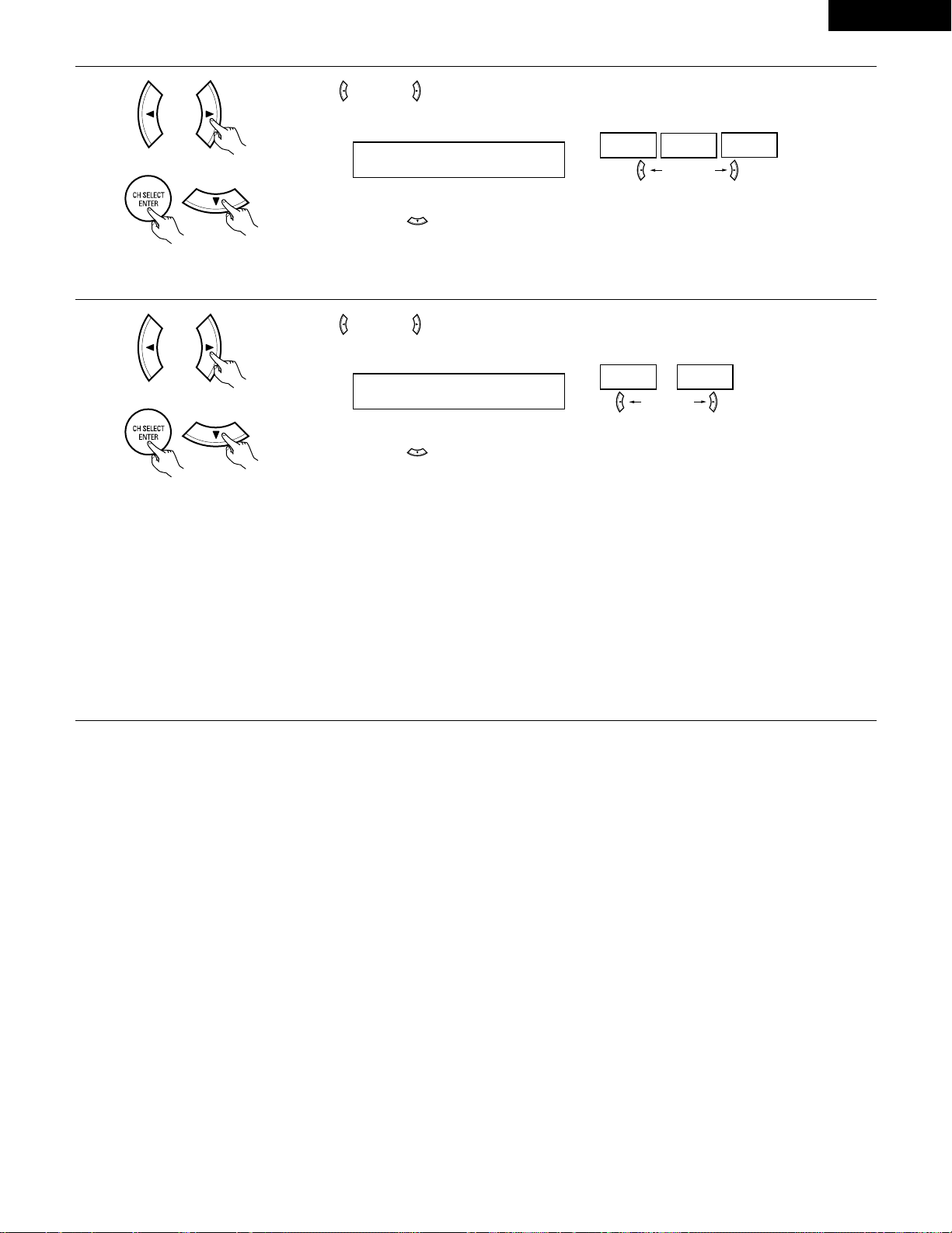
19
ENGLISH
5
Use the (left) and (right) buttons to select your subwoofer setting.
(left) button (right) button
Press the ENTER or (down) button to enter the settings and switch to the subwoofer mode setting.
• Parameters
Large…… Select this when using speakers that can fully reproduce low sounds of below 80 Hz.
Small…… Select this when using speakers that cannot reproduce low sounds of below 80 Hz with sufficient volume. When this setting is
selected, low frequencies of below 80 Hz are assigned to the subwoofer.
None…… Select this when no speakers are installed.
Yes/No…. Select “Yes” when a subwoofer is installed, “No” when it’s not installed.
NOTE:
Select “Large” or “Small” not according to the physical size of the speaker , but according to the bass reproduction capacity at 80 Hz. If you cannot
determine the best setting, try comparing the sound when set to “Small” and when set to “Large”, at a level that will not damage the speakers.
Caution:
In case the subwoofer is not used, be sure to set “Subwoofer = No”, or the bass sound of front channel is divided to subwoofer channel and
not reproduced in some mode.
(Initial)
4
Use the (left) and (right) buttons to select your surround back speaker type.
4 S.BACK SMALL
LARGE
SMALL
NONE
(left) button (right) button
Press the ENTER or (down) button to switch to the subwoofer setting.
(Initial)
NOTE:
• When “Small” has been selected for the surround speakers, “Large” cannot be selected for the surround back speakers.
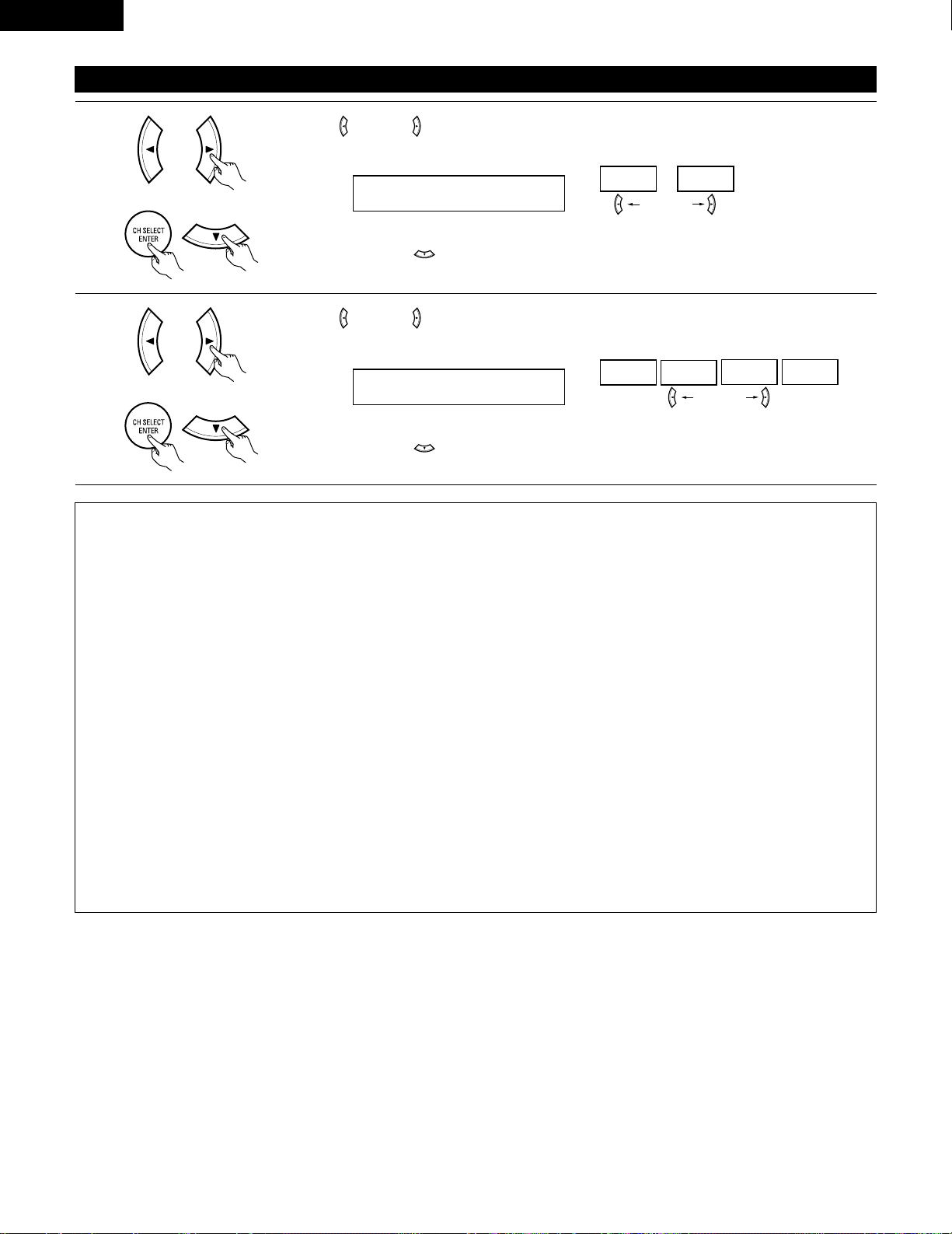
20
ENGLISH
NOTES:
— Assignment of low frequency signal range —
• The signals produced from the subwoofer channel are LFE signals (during playback of Dolby Digital or DTS signals) and the low frequency
signal range of channels set to “SMALL” in the setup. The low frequency signal range of channels set to “LARGE” are produced from those
channels.
— Crossover Frequency —
• When “Subwoofer” is set to “Yes” at the “Speaker Configuration Setting”, set the frequency (Hz) below which the bass sound of the
various speakers is to be output from the subwoofer (the crossover frequency).
• For speakers set to “Small”, sound with a frequency below the crossover frequency is cut, and the cut bass sound is output from the
subwoofer instead.
NOTE: For ordinary speaker systems, we recommend setting the crossover frequency to 80 Hz. When using small speakers, however,
setting the crossover frequency to a high frequency may improve frequency response for frequencies near the crossover frequency.
— Subwoofer mode —
• The subwoofer mode setting is only valid when “LARGE” is set for the front speakers and “YES” is set for the subwoofer in the “Speaker
Configuration” settings (see pages 18, 19).
If “SMALL” is set for the front speakers or “NO” is set for the subwoofer, the subwoofer mode setting does not affect playback of low
frequency signal range.
• When the “+MAIN” playback mode is selected, the low frequency signal range of channels set to “LARGE” are produced simultaneously
from those channels and the subwoofer channel.
In this playback mode, the low frequency range expand more uniformly through the room, but depending on the size and shape of the room,
interference may result in a decrease of the actual volume of the low frequency range.
• When the “NORM” playback mode is selected, the low frequency signal range of channels set to “LARGE” are only produced from those
channels. In this playback mode there tends to be little interference of the low frequency range in the room.
• Try playing the music or movie source and select the playback mode providing the stronger low frequency range sound.
Setting the Subwoofer mode and Crossover Frequency
1
Use the (left) and (right) buttons to select the Subwoofer mode.
6 SW MODE NORM
NORM +MAIN
(left) button (right) button
Press the ENTER or (down) button to enter the setting and switch to the Crossover Frequency
setting.
(Initial)
2
Use the (left) and (right) buttons to select the Crossover Frequency.
7 CR.OVER 80Hz
80Hz
100Hz
120Hz 150Hz
(left) button (right) button
Press the ENTER or (down) button to enter the setting and switch to the SPEAKER DISTANCE
setting.
(Initial)
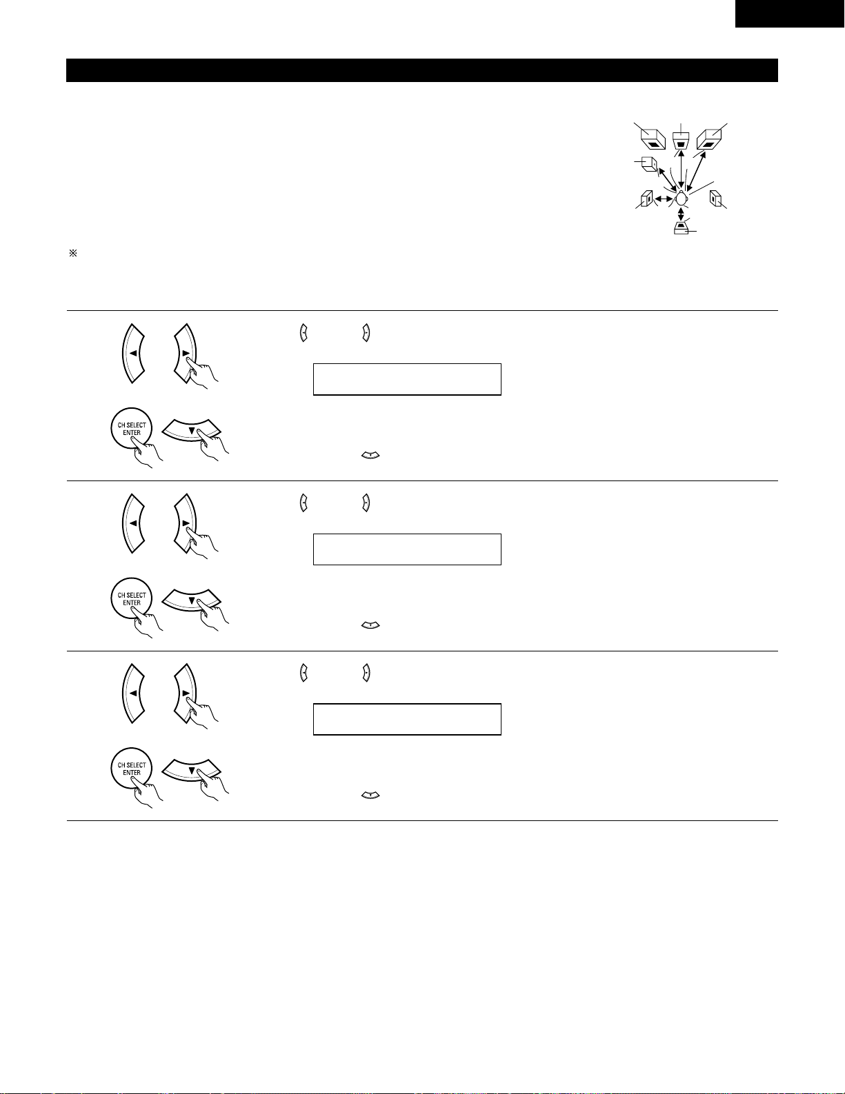
21
ENGLISH
3
Use the (left) and (right) buttons to set the distance from the center speaker to the listening position.
• The number changes in units of 1 foot each time one of the buttons is pressed. Select the value closest
to the measured distance.
Press the ENTER or (down) button to switch to the surround L speakers setting.
Setting the delay time
• Input the distance between the listening position and the different speakers to set the delay time for the surround mode.
Preparations:
Measure the distances between the listening position and the speakers (L1 to L5) on the diagram at
the right).
L1: Distance between center speaker and listening position
L2: Distance between front speakers and listening position
L3: Distance between surround speakers and listening position
L4: Distance between surround back speaker and listening position
L5: Distance between subwoofer and listening position
CAUTION:
Please note that the difference for every speaker should be 15 ft or less.
NOTE:
• No setting when “None” has been selected for the Speaker Configuration setting.
Center FRFL
Subwoofer
SL
Listening position
SR
SB
1
Use the (left) and (right) buttons to set the distance from the front L speaker to the listening position.
• The number changes in units of 1 foot each time one of the buttons is pressed. Select the value closest
to the measured distance.
Press the ENTER or (down) button to switch to the front R speaker setting.
2
Use the (left) and (right) buttons to set the distance from the front R speaker to the listening position.
• The number changes in units of 1 foot each time one of the buttons is pressed. Select the value closest
to the measured distance.
Press the ENTER or (down) button to switch to the center speaker setting.
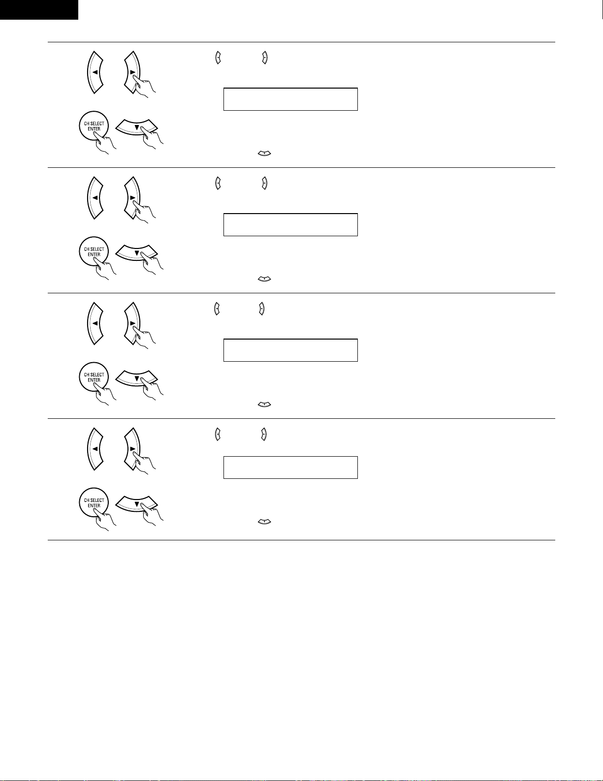
22
ENGLISH
6
Use the (left) and (right) buttons to set the distance from the surround back speakers to the listening
position.
• The number changes in units of 1 foot each time one of the buttons is pressed. Select the value closest
to the measured distance.
Press the ENTER or (down) button to switch to the subwoofer setting.
5
Use the (left) and (right) buttons to set the distance from the surround R speakers to the listening
position.
• The number changes in units of 1 foot each time one of the buttons is pressed. Select the value closest
to the measured distance.
Press the ENTER or (down) button to switch to the surround back speaker setting.
7
Use the (left) and (right) buttons to set the distance from the subwoofer to the listening position.
• The number changes in units of 1 foot each time one of the buttons is pressed. Select the value closest
to the measured distance.
Press the ENTER or (down) button to enter the setting and switch the Test Tone setting.
4
Use the (left) and (right) buttons to set the distance from the surround L speakers to the listening
position.
• The number changes in units of 1 foot each time one of the buttons is pressed. Select the value closest
to the measured distance.
Press the ENTER or (down) button to switch to the surround R speaker setting.
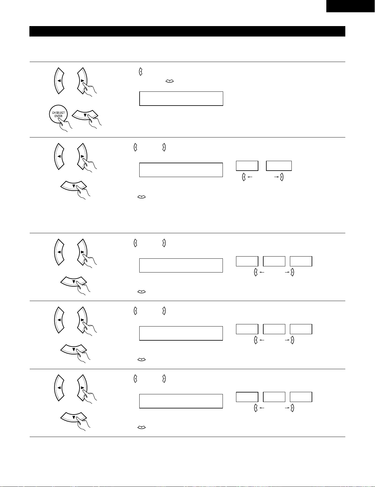
23
ENGLISH
Setting the Test Tone
• Use this setting to adjust to that the playback level between the different channel is equal.
• From the listening position, listen to the test tones produced from the speakers to adjust the level.
• The level can also be adjusted directly from the remote control unit. (For details, see page 37.)
1
• Use the (left) button to switch the Test Tone mode.
• Press the ENTER or (down) button to switch to the DIGITAL input (COAX) setting.
2
Use the (left) and (right) buttons to select the Test Tone mode.
Press the (down) button to start Test Tone.
(left) button (right) button
3
Use the (left) and (right) buttons to set the front L channel level.
Press the (down) button to switch to the center channel level (manual mode).
(left) button (right) button
4
Use the (left) and (right) buttons to set the center channel level.
Press the (down) button to switch to the front R channel level (manual mode).
(left) button (right) button
5
Use the (left) and (right) buttons to set the front R channel level.
Press the (down) button to switch to the surround R channel level (manual mode).
(left) button (right) button
(Initial)
• Auto:
Adjust the level while listening to the test tones produced automatically from the different speakers.
• Manual:
Select the speaker from which you want to produce the test tone to adjust the level.
(Initial)
(Initial)
(Initial)
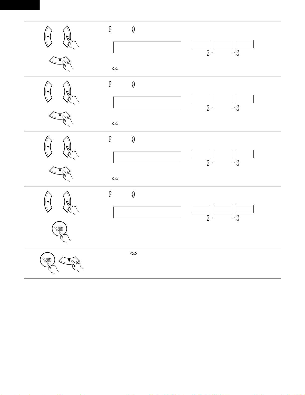
24
ENGLISH
6
Use the (left) and (right) buttons to set the surround R channel level.
Press the (down) button to switch to the surround back channel level (manual mode).
(left) button (right) button
7
Use the (left) and (right) buttons to set the surround back channel level.
Press the (down) button to switch to the surround L channel level (manual mode).
(left) button (right) button
8
Use the (left) and (right) buttons to set the surround L channel level.
Press the (down) button to switch to the subwoofer channel level (manual mode).
(left) button (right) button
9
Use the (left) and (right) buttons to set the subwoofer channel level.
Press the ENTER button to finish the Test Tone.
(left) button (right) button
10
Press the ENTER or (down) button to switch the DIGITAL input (COAX) setting.
(Initial)
(Initial)
(Initial)
(Initial)
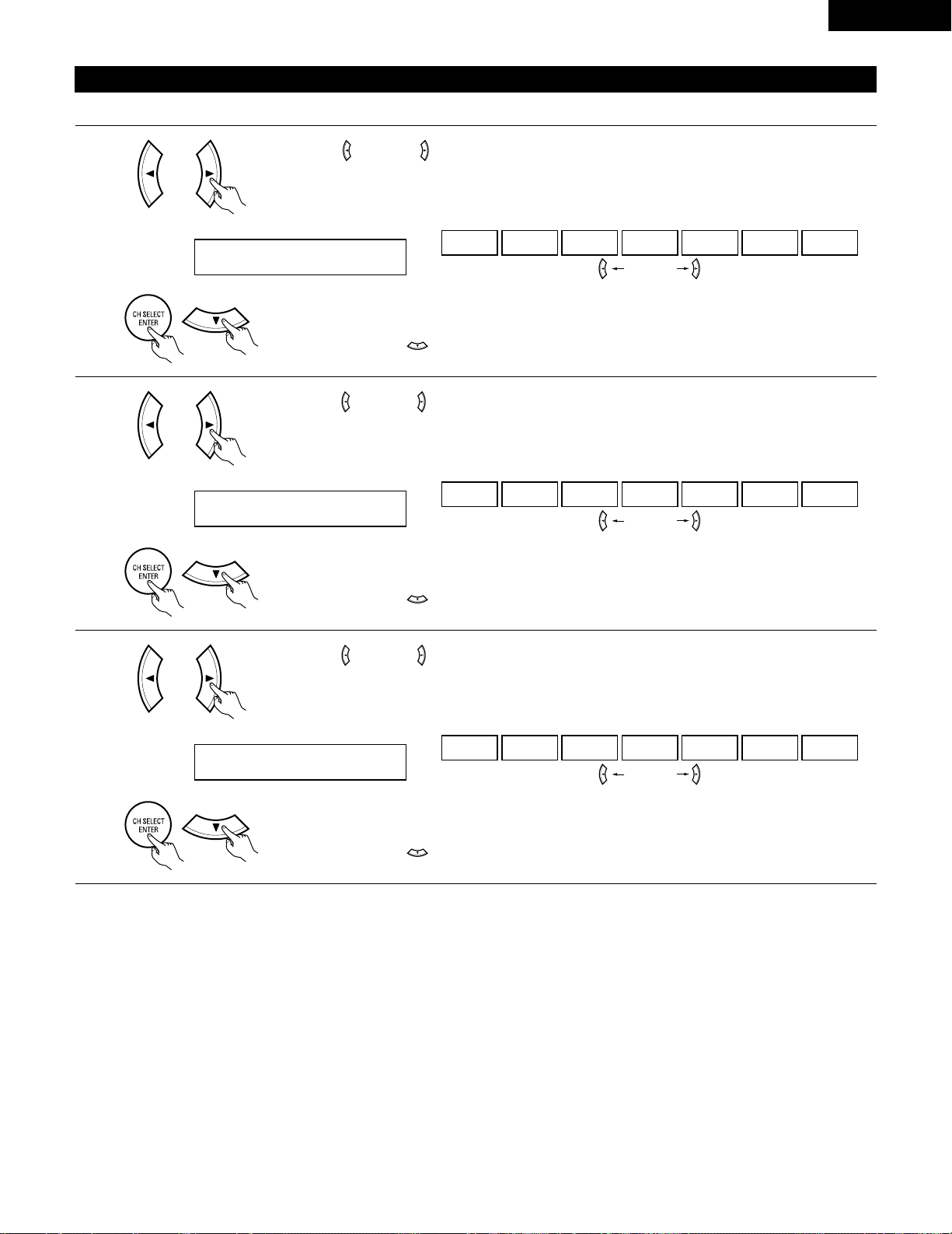
25
ENGLISH
NOTE:
• TUNER, V. AUX cannot be selected.
3
Use the (left) and (right) buttons to assign the input function connected to the OPTICAL input 2
(OPTICAL 2) terminal.
18 OPT2 TV
CD AUX DVD TV VCR CDR OFF
• Select “OFF” if nothing is connected.
Press the ENTER or (down) button to switch the auto surround mode setting.
(left) button (right) button
(Initial)
Setting the Digital In assignment
Input the type of components connected to the digital input terminals.
1
Use the (left) and (right) buttons to assign the input function connected to the COAXIAL input
(COAXIAL) terminal.
16 COAX CD
CD AUX DVD TV VCR CDR OFF
• Select “OFF” if nothing is connected.
Press the ENTER or (down) button to switch the optical input 1 (OPT1) setting.
(left) button (right) button
2
Use the (left) and (right) buttons to assign the input function connected to the OPTICAL input 1
(OPTICAL 1) terminal.
17 OPT1 DVD
CD AUX DVD TV VCR CDR OFF
• Select “OFF” if nothing is connected.
Press the ENTER or (down) button to switch the optical input 2 (OPT2) setting.
(left) button (right) button
(Initial)
(Initial)
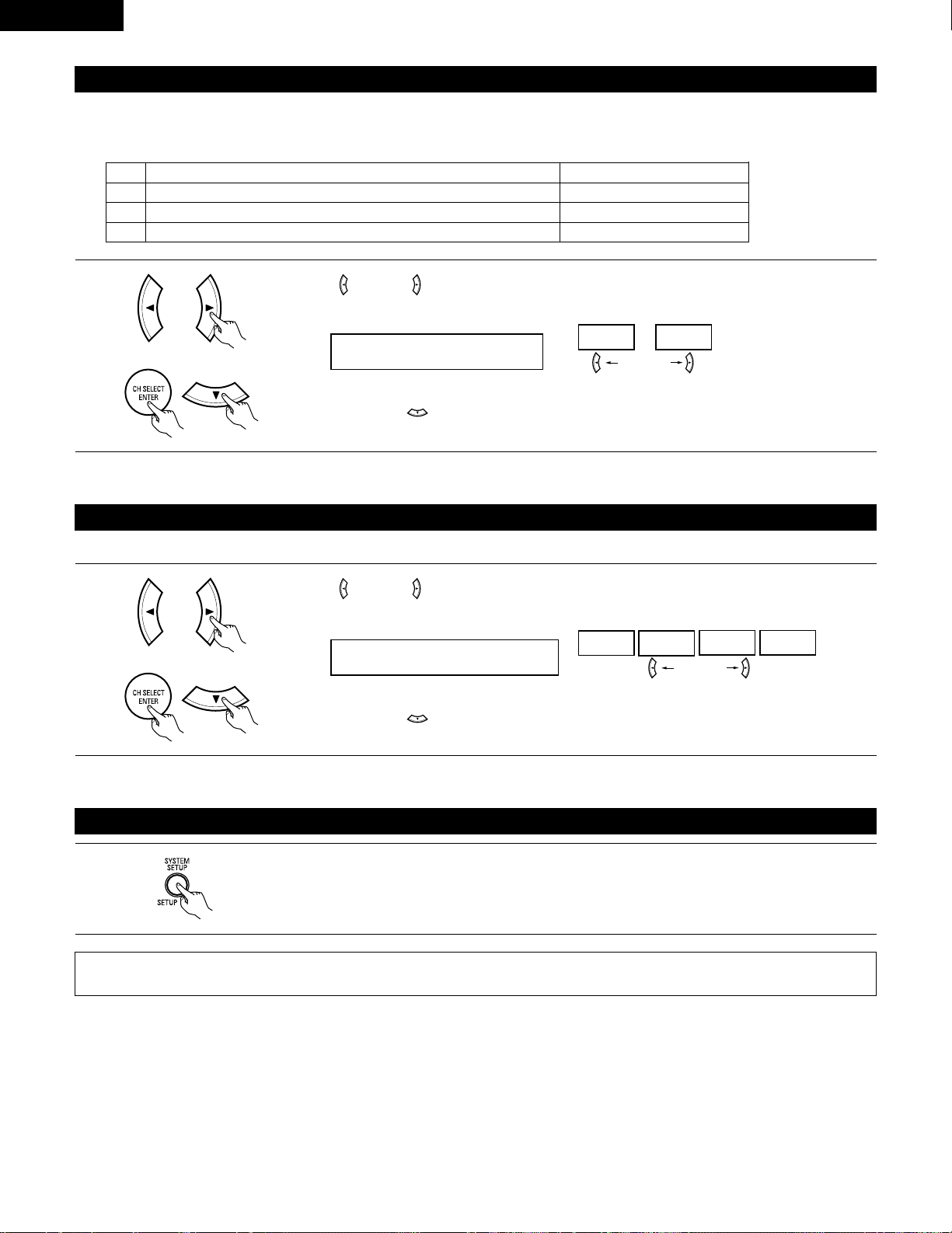
26
ENGLISH
After setting up the system
1
Press the SYSTEM SETUP button to finish system set up.
This completes the system setup operations. Once the system is set up, there is no need to make the settings again unless other components
or speakers are connected to or the speaker layout is changed.
Setting the Auto Surround Mode
For the three kinds of input signals as shown below, the surround mode played the last is stored in the memory. At next time it the same signal
inputs, the memorized surround mode is automatically selected and the signal is played.
Note that the surround mode setting is also stored separately for the different input function.
SIGNAL Default Auto Surround Mode
q Analog and PCM 2-channel signals STEREO
w 2-channel signals of Dolby Digital, DTS or other multichannel format Dolby PL
II Cinema
e Multichannel signals of Dolby Digital, DTS or other multichannel format Dolby or DTS Surround
1
Use the (left) and (right) buttons to select the Auto Surround mode.
(left) button (right) button
Press the ENTER or (down) button to switch the Ext. In SW Level setting.
(Initial)
Setting the Ext. In SW Level
Set the method of playback of the analog input signal connected to the Ext. In terminal.
1
Use the (left) and (right) buttons to select the Ext. In Subwoofer channel Level playback.
20 EXT.IN SW +15
+00
+05
+10 +15
(left) button (right) button
Press the ENTER or (down) button if you want to start the settings over from the beginning.
(Initial)
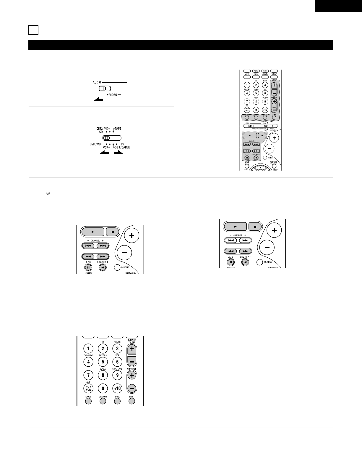
27
ENGLISH
Operating DENON audio components
• Turn on the power of the different components before operating them.
1
2
3
Set mode switch 1 to “AUDIO”.
Set mode switch 2 to the position for the component to be
operated. (CD, CDR/MD or Tape deck)
Operate the audio component.
• For details, refer to the component’s operating instructions.
While this remote control is compatible with a wide range of infrared controlled components, some models of components may not
be operated with this remote control.
1. CD player (CD) and CD recorder and MD recorder
(CDR/MD) system buttons
3. Tuner system buttons
2. Tape deck (TAPE) system buttons
6, 7 : Manual search (forward and reverse)
2 : Stop
1 : Play
8, 9 : Auto search (cue)
3 : Pause
DISC : Switch discs
SKIP+ (for CD changers only)
SHIFT : Switch preset channel range
CHANNEL : Preset channel
+, – up/down
TUNING : Frequency
+, – up/down
BAND : Switch between the AM and FM bands
MODE : Switch between auto and mono
MEMORY : Preset memory
6 : Rewind
7 : Fast-forward
2 : Stop
1 : Forward play
0 : Reverse play
A/B : Switch between decks A and B
11
REMOTE CONTROL UNIT
NOTE:
• TUNER can be operated when the switch is at “AUDIO” position.
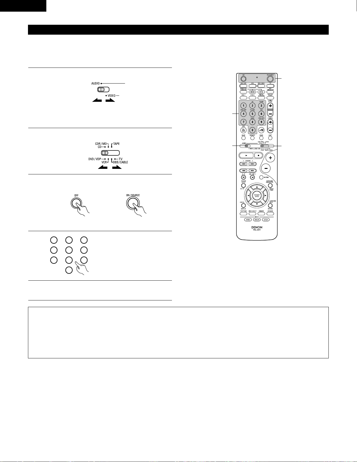
28
ENGLISH
Preset memory
DENON and other makes of components can be operated by setting the preset memory.
This remote control unit can be used to operate components of other manufacturers without using the learning function by registering the
manufacturer of the component as shown on the List of Preset Codes (pages 122~126).
Operation is not possible for some models.
1
2
Set mode switch 1 to “AUDIO” or “VIDEO”.
Set mode switch 2 to the component to be registered.
Set the AUDIO side for the CD, Tape deck or CDR/MD
position, to the VIDEO side for the DVD/VDP, DBS/CABLE,
VCR or TV position.
3
Press the ON/SOURCE button and the OFF button at the
same time.
• Indicator flash.
4
5
Referring to the included List of
Preset Codes, use the number
buttons to input the preset code (a
3-digit number) for the manufacturer
of the component whose signals
you want to store in the memory.
To store the codes of another component in the memory,
repeat steps 1 to 4.
The preset codes are as follows upon shipment from the factory and after resetting:
TV, VCR ……………………………………………..HITACHI
CD, TAPE…………………………………………..DENON
CDR/MD ……………………………………………DENON (CDR)
DVD/VDP …………………………………………..DENON (DVD)
DBS/CABLE……………………………………….ABC (CABLE)
NOTES:
• The signals for the pressed buttons are emitted while setting the preset memory. To avoid accidental operation, cover the remote control
unit’s transmitting window while setting the preset memory.
• Depending on the model and year of manufacture, this function cannot be used for some models, even if they are of makes listed on the
included list of preset codes.
• Some manufacturers use more than one type of remote control code. Refer to the included list of preset codes to change the number and
check.
• The preset memory can be set for one component only among the following: CDR/MD, DVD/VDP and DBS/CABLE.
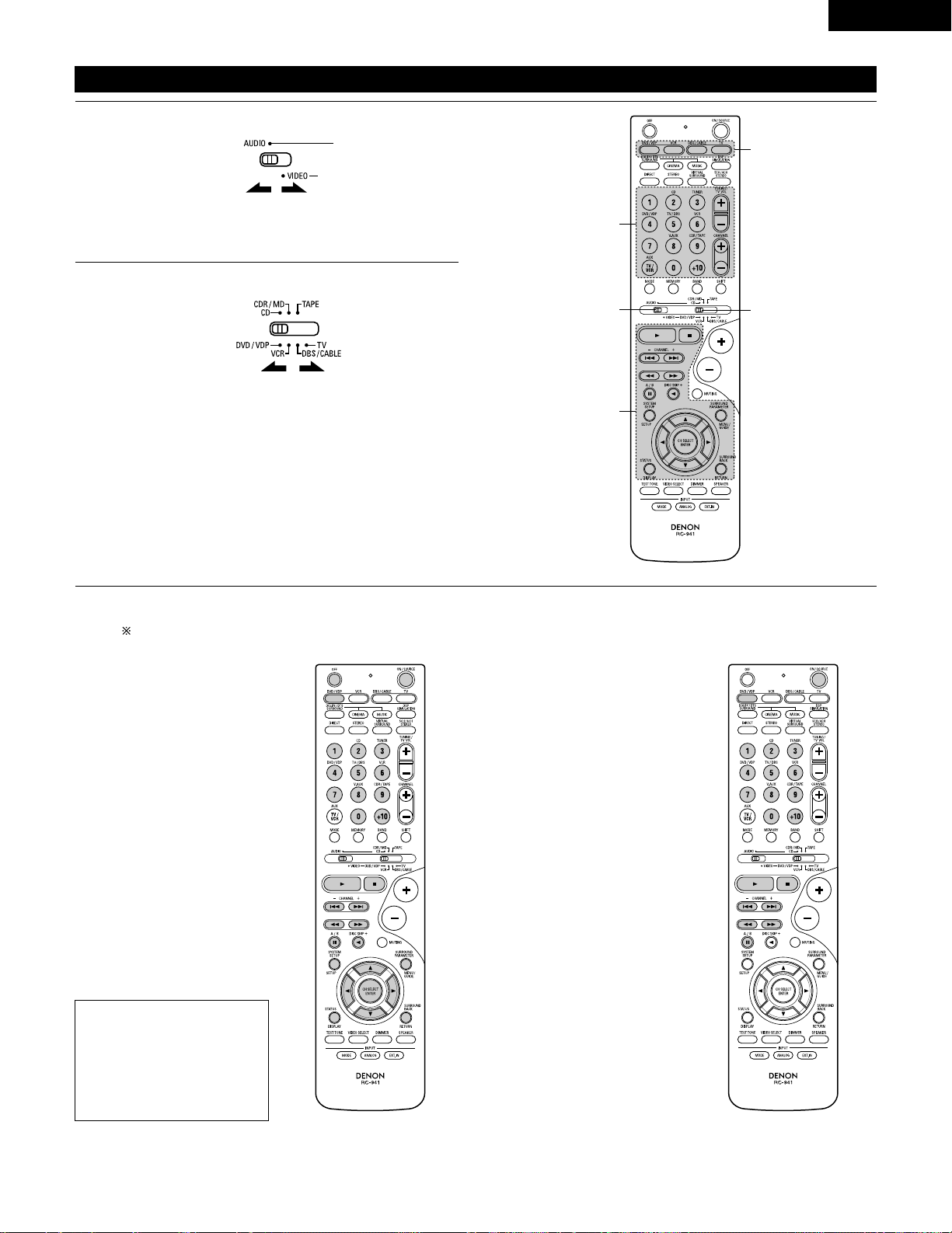
29
ENGLISH
Operating component stored in the preset memory
1
2
Set mode switch 1 to “AUDIO” or “VIDEO”.
Set mode switch 2 to the component you want to operate.
Set the AUDIO side for the CD, tape deck or CDR/MD
position, to the VIDEO side for the DVD/VDP, DBS/CABLE,
VCR or TV position.
1. Digital video disc player (DVD,
DVD SETUP) system buttons
POWER : Power on/standby
(ON/SOURCE)
OFF : DENON DVD power off
6,7 : Manual search
(forward and reverse)
2 : Stop
1 :Play
8,9 : Auto search
(to beginning of track)
3 : Pause
0 ~ 9, +10 : 10 key
skip + : Disc skip
(for DVD changer only)
DISPLAY : Switch display
MENU : Menu
RETURN : Return
SETUP : Setup
•, ª,
0, 1
: Cursor up, down, left
and right
ENTER : Enter setting
2. Video disc player (VDP)
system buttons
POWER : Power on/standby
(ON/SOURCE)
6,7 : Manual search
(forward and reverse)
2 : Stop
1 :Play
8,9 : Auto search (cue)
3 : Pause
0~9, +10 : 10 key
3
Operate the component.
• For details, refer to the component’s operating instructions.
Some models cannot be operated with this remote control unit.
NOTE:
• Some manufacturers use
different names for the DVD
remote control buttons, so
also refer to the instructions
on remote control for that
component.
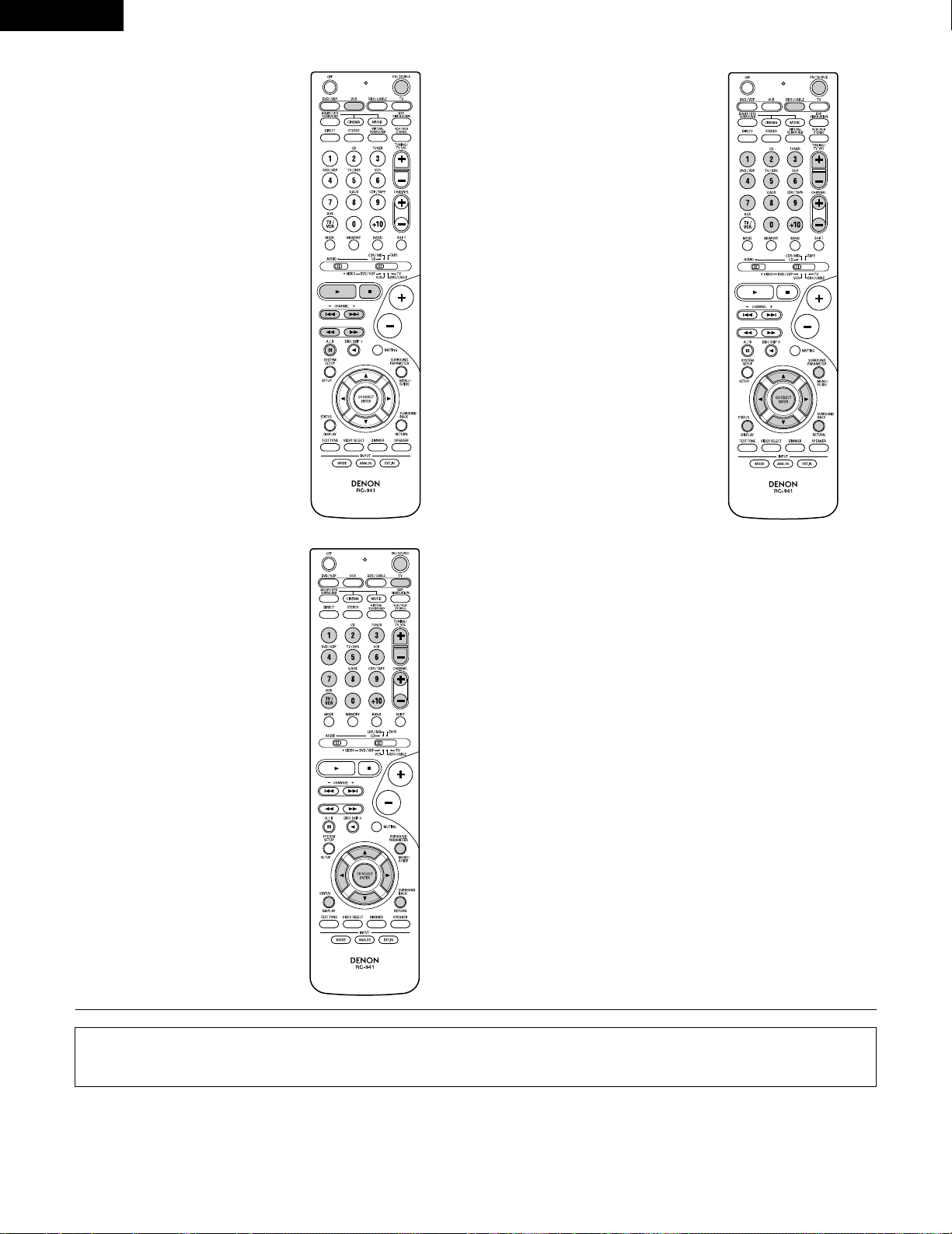
30
ENGLISH
3. Video deck (VCR) system
buttons
4. Digital broadcast satellite
(DBS) tuner and cable
(CABLE) system buttons
POWER : Power on/standby
(ON/SOURCE)
6,7 : Manual search
(forward and reverse)
2 : Stop
1 :Play
3 : Pause
Channel +, – : Channels
POWER : Power on/standby
(ON/SOURCE)
MENU : Menu
RETURN : Return
•, ª,
0, 1
: Cursor up, down, left
and right
ENTER : Enter
CHANNEL : Switch channels
+, –
0~9, +10 : Channels
DISPLAY : Switch display
VOL +, – : Volume up/down
5. Monitor TV (TV) system
buttons
POWER : Power on/standby
(ON/SOURCE)
MENU : Menu
RETURN : Return
•, ª,
0, 1
: Cursor up, down, left
and right
ENTER : Enter
CHANNEL : Switch channels
+, –
0~9, +10 : Channels
DISPLAY : Switch display
TV/VCR : Switch between TV
and video player
TV VOL : Volume up/down
+, –
NOTES:
• For this CD, CDR, MD and TAPE components, buttons can be operated in the same way as for Denon audio components (page 27).
• The TV can be operated when the switch is at DVD/VDP, VCR, TV position.
Loading…
-
Страница 1
2 We greatly appreciate your purchase of this unit. 2 T o be sure you take maximum advantage of all the features this unit has to offer , read these instructions carefully and use the set properly . Be sure to keep this manual for future reference should any questions or problems arise. “SERIAL NO. PLEASE RECORD UNIT SERIAL NUMBER A TTACHED TO TH[…]
-
Страница 2
2 ENGLISH 2 SAFETY PRECAUTIONS 2 NOTE ON USE / OBSERV A TIONS RELA TIVES A L ’UTILISA TION • Avoid high temperatures. Allow for sufficient heat dispersion when installed on a rack. • Eviter des températures élevées. T enir compte d’une dispersion de chaleur suffisante lors de l’installation sur une étagère. • Handle the power cord […]
-
Страница 3
3 SAFETY INSTRUCTIONS 1. Read Instructions – All the safety and operating instructions should be read before the product is operated. 2. Retain Instructions – The safety and operating instructions should be retained for future reference. 3. Heed Warnings – All warnings on the product and in the operating instructions should be adhered to. 4. […]
-
Страница 4
4 ENGLISH 2 INTRODUCTION 2 ACCESSORIES Thank you for choosing the DENON A/V Surround receiver . This remarkable component has been engineered to provide superb surround sound listening with home theater sources such as DVD, as well as providing outstanding high fidelity reproduction of your favorite m usic sources. As this product is provided with […]
-
Страница 5
5 ENGLISH 3 CAUTIONS ON HANDLING 4 FEA TURES • Switching the input function when input jacks are not connected A clicking noise may be produced if the input function is switched when nothing is connected to the input jacks. If this happens, either turn down the MASTER VOLUME control or connect components to the input jacks. • Muting of PRE OUT […]
-
Страница 6
6 ENGLISH 5 P AR T NAMES AND FUNCTIONS Front Panel • For details on the functions of these parts, refer to the pages given in parentheses ( ). q w u e i r y o! 4 t !1 @1 @2 @3 @4 @5 @6 @7 @8 @9 !2 !3 !5 !6 !7 !0 !8 @0 !9 #0 q Power operation switch ……………………………………….(18, 32, 51) w Headphones jack (PHONES)…………..[…]
-
Страница 7
NOTE: • The shaded buttons do not function with the A VR-1604/684. (Nothing happens when they are pressed.) 7 ENGLISH Remote control unit • For details on the functions of these parts, refer to the pages given in parentheses ( ). SURROUND buttons ……………………………..(34, 37, 47) Cursor buttons………………………..(17, 29,[…]
-
Страница 8
8 ENGLISH 6 READ THIS FIRST This A V Surround Receiver must be setup before use. Following these steps. 7 SETTING UP THE SPEAKER SYSTEMS Step 3 (page 17 to 26) Finally , setting up the system. Step 2 (page 16) Next, insert the batteries into the remote control unit. Step 1 (page 8 to 15) Choose the best location to setup the Speakers and connecting[…]
-
Страница 9
9 ENGLISH 8 CONNECTIONS • Do not plug in the power cord until all connections have been completed. • Be sure to connect the left and right channels properly (left with left, right with right). • Insert the plugs securely . Incomplete connections will result in the generation of noise. • Use the AC OUTLETS for audio equipment only . Do not u[…]
-
Страница 10
10 ENGLISH Connecting the video equipments T o connect the video signal, connect using a 75 Ω /ohms video signal cable cord. Using an improper cable can result in a drop in sound quality . IN VIDEO R L R L R L L R R OUT IN AUDIO VIDEO OUT IN LRL R L R L R OUT VIDEO OUT L AUDIO OUT COAXIAL DIGITAL L R R OUT VIDEO OPTICAL OUT L AUDIO OUT DIGITAL L […]
-
Страница 11
11 ENGLISH Connecting a video component equipped with S-video jacks • When marking connections, also refer to the operating instructions of the other components. • A note on the S input jacks The input selectors for the S inputs and pin jack inputs work in conjunction with each other . • Precaution when using S-jacks This unit’ s S-jacks (i[…]
-
Страница 12
12 ENGLISH VIDEO OUT Y C R C B COMPONENT YC R C B VIDEO IN COMPONENT B Connecting a Video Component Equipped with Color Difference (Component — Y , P R /C R , P B /C B ) Video Jacks (DVD Player) • When making connections, also refer to the operating instructions of the other components. • The signals input to the color difference (component) vi[…]
-
Страница 13
13 ENGLISH 1 4 2 3 Connecting the antenna terminals DIRECTION OF BROADCASTING ST A TION AM LOOP ANTENNA (An Accessory) FM ANTENNA GROUND AM OUTDOOR ANTENNA FM INDOOR ANTENNA (An Accessory) 75 Ω /ohms COAXIAL CABLE AM loop antenna assembly Connect to the AM antenna terminals. Bend in the reverse direction. Remove the vinyl tie and take out the con[…]
-
Страница 14
14 ENGLISH Speaker system connections • Connect the speaker terminals with the speakers making sure that like polarities are matched ( < with < , > with > ). Mismatching of polarities will result in weak central sound, unclear orientation of the various instruments, and the sense of direction of the stereo being impaired. • When mak[…]
-
Страница 15
15 ENGLISH Protector circuit • This unit is equipped with a high-speed protection circuit. The purpose of this circuit is to protect the speakers under circumstances such as when the output of the power amplifier is inadvertently short-circuited and a large current flows, when the temperature surrounding the unit becomes unusually high, or when t[…]
-
Страница 16
16 ENGLISH 9 USING THE REMOTE CONTROL UNIT Following the procedure outlined below , insert the batteries before using the remote control unit. Range of operation of the remote control unit Inserting the batteries Point the remote control unit at the remote control sensor as shown on the diagram at the left. NOTES: • The remote control unit can be[…]
-
Страница 17
17 ENGLISH 10 SETTING UP THE SYSTEM • Once all connections with other A V components have been completed as described in “ CONNECTIONS ” (see pages 9 to 15), make the various settings described below on the display . These settings are required to set up the listening room ’ s A V system centered around the this unit. SYSTEM SETUP button Pr[…]
-
Страница 18
18 ENGLISH Before setting up the system 1 2 Press the SYSTEM SETUP button to enter the setting. Check that all the components are correct, then press the POWER operation switch on the main unit or the POWER button on the remote control unit to turn on the power . 3 Press the ENTER or (down) button to switch to the speaker configuration set up. *SYS[…]
-
Страница 19
19 ENGLISH 5 Use the (left) and (right) buttons to select your subwoofer setting. 5 S.WOOFER YES YES NO (left) button (right) button Press the ENTER or (down) button to enter the settings and switch to the subwoofer mode setting. • Parameters Large …… Select this when using speakers that can fully reproduce low sounds of below 80 Hz. Small ?[…]
-
Страница 20
20 ENGLISH NOTES: — Assignment of low frequency signal range — • The signals produced from the subwoofer channel are LFE signals (during playback of Dolby Digital or DTS signals) and the low f requency signal range of channels set to “ SMALL ” in the setup. The low frequency signal range of channels set to “ LARGE ” are produced from […]
-
Страница 21
21 ENGLISH 3 Use the (left) and (right) buttons to set the distance from the center speaker to the listening position. 10 CENTER 12ft • The number changes in units of 1 foot each time one of the buttons is pressed. Select the value closest to the measured distance. Press the ENTER or (down) button to switch to the surround L speakers setting. Set[…]
-
Страница 22
22 ENGLISH 6 Use the (left) and (right) buttons to set the distance from the surround back speakers to the listening position. 13 S.BACK 10ft • The number changes in units of 1 foot each time one of the buttons is pressed. Select the value closest to the measured distance. Press the ENTER or (down) button to switch to the subwoofer setting. 5 Use[…]
-
Страница 23
23 ENGLISH Setting the T est T one • Use this setting to adjust to that the playback level between the different channel is equal. • From the listening position, listen to the test tones produced from the speakers to adjust the level. • The level can also be adjusted directly from the remote control unit. (For details, see page 37.) 1 • Use[…]
-
Страница 24
24 ENGLISH 6 Use the (left) and (right) buttons to set the surround R channel level. AUTO-SR -12dB 0dB +12dB Press the (down) button to switch to the surround back channel level (manual mode). (left) button (right) button 7 Use the (left) and (right) buttons to set the surround back channel level. AUTO-SB -12dB 0dB +12dB Press the (down) button to […]
-
Страница 25
25 ENGLISH NOTE: • TUNER, V . AUX cannot be selected. 3 Use the (left) and (right) buttons to assign the input function connected to the OPTICAL input 2 (OPTICAL 2) terminal. 18 OPT2 TV CD AUX DVD TV VCR CDR OFF • Select “ OFF ” if nothing is connected. Press the ENTER or (down) button to switch the auto surround mode setting. (left) button[…]
-
Страница 26
26 ENGLISH After setting up the system 1 Press the SYSTEM SETUP button to finish system set up. This completes the system setup operations. Once the system is set up, there is no need to make the settings again unless other components or speakers are connected to or the speaker layout is changed. Setting the Auto Surround Mode For the three kinds o[…]
-
Страница 27
27 ENGLISH Operating DENON audio components • T urn on the power of the different components before operating them. 1 2 3 Set mode switch 1 to “ AUDIO ” . Set mode switch 2 to the position for the component to be operated. (CD, CDR/MD or T ape deck) Operate the audio component. • For details, refer to the component ’ s operating instructi[…]
-
Страница 28
28 ENGLISH Preset memory DENON and other makes of components can be operated by setting the preset memory . This remote control unit can be used to operate components of other manufacturers without using the learning function by registering the manufacturer of the component as shown on the List of Preset Codes (pages 122~126). Operation is not poss[…]
-
Страница 29
29 ENGLISH Operating component stored in the preset memory 1 2 Set mode switch 1 to “ AUDIO ” or “ VIDEO ” . Set mode switch 2 to the component you want to operate. 3 2 1 3 3 Set the AUDIO side for the CD, tape deck or CDR/MD position, to the VIDEO side for the DVD/VDP , DBS/CABLE, VCR or TV position. 1. Digital video disc player (DVD, DVD […]
-
Страница 30
30 ENGLISH 3. Video deck (VCR) system buttons 4. Digital broadcast satellite (DBS) tuner and cable (CABLE) system buttons POWER : Power on/standby (ON/SOURCE) 6 , 7 : Manual search (forward and reverse) 2 : Stop 1
l a y 3 : Pause Channel +, – : Channels POWER : Power on/standby (ON/SOURCE) MENU : Menu RETURN : Return • , ª , 0 , 1 : Cursor […] -
Страница 31
31 ENGLISH T able 1 Punch Through •“ Punch Through ” is a function allowing you to operate the PLA Y , STOP , MANUAL SEARCH and AUTO SEARCH buttons on the CD, T APE, CDR/MD, DVD/VDP or VCR components when in the DBS/CABLE or TV mode. By default, nothing is set. 1 2 Set mode switch 1 to “ VIDEO ” . Set mode switch 2 to the component to be […]
-
Страница 32
32 ENGLISH 12 OPERA TION Before operating Preparations: Check that all connections are proper . 1 T urn on the power . Press the ON/ST ANDBY button on the main unit or ON/SOURCE button on the remote control unit to turn on the power . 2 Select the front speakers. Press the SPEAKER A or B button to turn the speaker on. (Main unit) (Remote control un[…]
-
Страница 33
33 ENGLISH Playing the input source 3 1 2 5 Input mode selection function Different input modes can be selected for the different input sources. The selected input modes for the separate input sources are stored in the memory . q AUTO (All auto mode) In this mode, the types of signals being input to the digital and analog input jacks for the select[…]
-
Страница 34
34 ENGLISH • T o increase the bass or treble: T urn the control clockwise. (The bass or treble sound can be increased to up to +12 dB in steps of 2 dB.) • T o decrease the bass or treble: T urn the control counterclockwise. (The bass or treble sound can be decreased to up to – 12 dB in steps of 2 dB.) T o select the surround mode while adjust[…]
-
Страница 35
35 ENGLISH Using the dimmer function • Use this to change the brightness of the display . The display brightness changes in four steps (bright, medium, dim and off) by pressing the main unit ’ s DIMMER button repeatedly . Front panel display • Descriptions of the unit ’ s operations are also displayed on the front panel display . In additio[…]
-
Страница 36
36 ENGLISH Set the external input (EXT . IN) mode. Press the EXT . IN to switch the external input. Once this is selected, the input signals connected to the FL (front left), FR (front right), C (center), SL (surround left), and SR (surround right) channels of the EXT . IN jacks are output directly to the front (left and right), center , surround ([…]
-
Страница 37
37 ENGLISH 13 SURROUND Before playing with the surround function • Before playing with the surround function, be sure to use the test tones to adjust the playback level from each speakers. This adjustment can be performed from the remote control unit, as (described) below . • The adjustment with the test tones is only effective in the DOLBY/DTS[…]
-
Страница 38
38 ENGLISH • After adjusting using the test tones, adjust the channel levels either according to the playback sources or to suit your tastes, as (described) below . 1 Select the speaker whose level you want to adjust. The channel switches as shown below each time the button is pressed. 3 Adjust the level of the selected speaker . FL CNTR FR SR SB[…]
-
Страница 39
39 ENGLISH Dolby Surround Pro Logic II mode 2 Select the Dolby Surround Pro Logic II mode. Light (Main unit) (Remote control unit) 3 Play a program source with the mark. • For operating instructions, refer to the manuals of the respective components. 5, 7 4, 6 1 2 4, 6 5, 7 1 8 5, 7 2 4 Select the surround parameter mode. MODE Dolby PL CINEMA EQ […]
-
Страница 40
40 ENGLISH NOTE: • When making parameter settings, the display will return to the regular condition several seconds after the last button was pressed and the setting will be completed. 7 Set the various surround parameters. • CINEMA EQ setting ON OFF or or CINEMA EQ OFF • P ANORAMA setting ON OFF or or PANORAMA OFF • DIMENSION setting 0 3 6[…]
-
Страница 41
41 ENGLISH 3 Play a program source. 4 Select the surround parameter mode. MODE CINEMA SURROUND BACK DEFAULT MODE MUSIC SURROUND BACK DEFAULT CINEMA EQ CENTER IMAGE TONE DEFEAT TONE DEFEAT or or MODE music MODE cinema (Main unit) (Remote control unit) T o perform this operation from the remote control unit, check that the mode selector switch is set[…]
-
Страница 42
42 ENGLISH Surround parameters q Pro Logic II Mode: • The Cinema mode is for use with stereo television shows and all programs encoded Dolby Surround. • The Music mode is recommended as the standard mode for autosound music systems (no video), and is optional for A/V systems. • The Pro Logic mode offers the same robust surround processing as […]
-
Страница 43
43 ENGLISH Dolby Digital mode (only with digital input) and DTS Surround (only with digital input) 1 Select the input source. q Select an input source set to digital (COAXIAL/OPTICAL) (see page 25). (Main unit) (Remote control unit) w Set the input mode to “ AUTO ” or DTS. 2 Select the Dolby/DTS Surround mode. (Remote control unit) 3 Play a pro[…]
-
Страница 44
44 ENGLISH Press the SURROUND P ARAMETER or (down) button to switch to the D. COMP . setting. Use the (left) and (right) buttons to set the CINEMA EQ. 5 CINEMA EQ OFF ON OFF (left) button (right) button (Initial) (Remote control unit) (Remote control unit) 6 Use the (left) and (right) buttons to set the D. COMP . D.COMP. OFF OFF LOW MID HIGH Press […]
-
Страница 45
45 ENGLISH 2 Dialogue Normalization The dialogue normalization function is activated automatically when playing Dolby Digital program sources. Dialogue normalization is a basic function of Dolby Digital which automatically normalizes the dialog level (standard level) of the signals which are recorded at different levels for different program source[…]
-
Страница 46
46 ENGLISH 14 DSP SURROUND SIMULA TION • This unit is equipped with a high performance DSP (Digital Signal Processor) which uses digital signal processing to synthetica lly recreate the sound field. One of 7 preset surround modes can be selected according to the program source and the parameters can be adjusted according to the conditions in the […]
-
Страница 47
47 ENGLISH DSP surround simulation 1 Select the surround mode for the input channel. (Remote control unit) The surround mode switches in the following order each time the DSP SIMULA TION button is pressed: 2 3 3 4 1 2 T o enter the surround parameter setting mode, press the SURROUND P ARAMETER button. • The surround parameter switches in the foll[…]
-
Страница 48
48 ENGLISH Use the (left) and (right) buttons to set the delay time. DELAY 30ms 110ms 30ms 0ms (left) button (right) button (Remote control unit) (3) DELA Y TIME (Remote control unit) (7) DEF AUL T T o reset the settings to the factory defaults, use the (left) and (right) buttons to display “ Ye s ” . DEFAULT Y/N NO Y/N YES (left) button (right[…]
-
Страница 49
49 ENGLISH 1 T urn the SELECT knob to select the surround mode. (Main unit) • When turned clockwise 2 Press the SURROUND P ARAMETER button. Press and hold in the surround parameter button to select the parameter you want to set. • The parameters which can be set differ for the different surround modes. (Refer to “ Surround Modes and Parameter[…]
-
Страница 50
50 ENGLISH C C E C * E C E E E E E E E C 2 Surround modes and parameters Channel output B B B B B B B B B B B B B B SUB- WOOFER E E B B B B B B B B B B B E SURROUND L/R E E B B B B B B B B B B B E CENTER C C C C C C C C C C C C C C FRONT L/R Mode DIRECT STEREO EXTERNAL INPUT DOLBY PRO LOGIC II DTS NEO:6 DOLBY DIGIT AL DTS SURROUND 5CH/6CH STEREO RO[…]
-
Страница 51
51 ENGLISH 15 LISTENING TO THE RADIO Auto preset memory 1 When the main unit ’ s power operation switch turn on while pressing the set ’ s PRESET D D button the unit automatically begins searching for FM broadcast stations. 2 When the first FM broadcast station is found, that station is stored in the preset memory at channel A1. Subsequent stat[…]
-
Страница 52
52 ENGLISH Press the TUNING D D (+) or H H ( – ) button to tune in the desired station. The frequency changes continuously when the button is held in. Auto tuning 1 Set the input source to “ TUNER ” . 2 Watching the display , press the BAND button to select the desired band (AM or FM). 3 Press the MODE button to set the auto tuning mode. Lit […]
-
Страница 53
53 ENGLISH Preset stations 1 Press the MEMORY button. 2 Press the SHIFT button and select the desired memory block (A to E). (Main unit) (Remote control unit) 3 Press the PRESET D D (+) or H H ( – ) button to select the desired preset channel (1 to 8). (Main unit) (Remote control unit) 4 Press the MEMORY button again to store the station in the p[…]
-
Страница 54
54 ENGLISH 16 LAST FUNCTION MEMORY • This unit is equipped with a last function memory which stores the input and output setting conditions as they were immediately before the power is switched off. • The unit is also equipped with a back-up memory . This function provides approximately one week of memory storage when the main unit ’ s power […]
-
Страница 55
55 ENGLISH 18 ADDITIONAL INFORMA TION Optimum surround sound for different sources There are currently various types of multi-channel signals (signals or formats with more than two channels). 2 T ypes of multi-channel signals Dolby Digital, Dolby Pro Logic, DTS, high definition 3-1 signals (Japan MUSE Hi-Vision audio), DVD-Audio, SACD (Super Audio […]
-
Страница 56
56 ENGLISH Surround back speakers A 6.1-channel system is a conventional 5.1-channel system to which the “ surround back ” (SB) channel has been added. This makes it easy to achieve sound positioned directly behind the listener , something that was previously difficult with sources designed for conven tional multi surround speakers. In addition[…]
-
Страница 57
57 ENGLISH • Set the front speakers, center speaker and subwoofer in the same positions as in example (1). • It is best to place the surround speakers directly at the side or slightly to the front of the viewing position, and 2 to 3 feet (60 to 90 cm) above the ears. • Same as surround back speaker installation method (1). Using dipolar speak[…]
-
Страница 58
58 ENGLISH Surround The A VR-1604/684 is equipped with a digital signal processing circuit that lets you play program sources in the surround mode to achieve the same sense of presence as in a movie theater . Dolby Surround (1) Dolby Digital Dolby Digital is the multi-channel digital signal format developed by Dolby Laboratories. Dolby Digital cons[…]
-
Страница 59
59 ENGLISH DTS Digital Surround Digital Theater Surround (also called simply DTS) is a multi-channel digital signal format developed by Digital Theater Systems . DTS offers the same “ 5.1 ” playback channels as Dolby Digital (front left, front right and center , surround left and surround right) as well as the stereo 2-channel mode. The signals[…]
-
Страница 60
60 ENGLISH DTS-ES Extended Surround TM DTS-ES Extended Surround is a new multi-channel digital signal format developed by Digital Theater Systems Inc. While offering high compatibility with the conventional DTS Digital Surround format, DTS-ES Extended Surround greatly improves the 360-degree surround impression and space expression thanks to furthe[…]
-
Страница 61
61 ENGLISH 19 TROUBLESHOOTING If a problem should arise,first check the following. 1. Are the connections correct ? 2. Have you operated the receiver according to the Operating Instructions ? 3. Are the speakers and other components operating property ? If this unit is not operating properly , check the items listed in the table below . Should the […]
-
Страница 62
62 ENGLISH 20 SPECIFICA TIONS 2 Audio section • Power amplifier Rated output: Front: 75 W + 75 W (8 Ω /ohms, 20 Hz ~ 20 kHz with 0.08% T .H.D.) 110 W + 110 W (6 Ω /ohms, 1 kHz with 0.7% T .H.D.) Center: 75 W (8 Ω /ohms, 20 Hz ~ 20 kHz with 0.08% T .H.D.) 110 W (6 Ω /ohms, 1 kHz with 0.7% T .H.D.) Surround: 75 W + 75 W (8 Ω /ohms, 20 Hz […]
-
Страница 63
63 FRANCAIS 2 INTRODUCTION 2 ACCESSOIRES Nous vous remercions d‘avoir choisi l’ampli-tuner A/V Surround de DENON. Ce remarquable composant a été fabriqué pour fournir une superbe écoute de sons d’ambiance avec des sources de cinéma domestiqu e telles que DVD, ainsi que pour assurer une formidable reproduction haute fidélité de vos sour[…]
-
Страница 64
64 FRANCAIS 3 PRECAUTIONS DE MANIPULA TION 4 CARACTERISTIQUES • Commutation de la fonction d’entrée lorsque les prises d’entrée ne sont pas connectées Un déclic peut être produit si la fonction d’entrée est commutée lorsque rien n’est connecté aux prises d’entrée. Dans ce cas, abaisser la commande MASTER VOLUME (volume de la ga[…]
-
Страница 65
65 FRANCAIS 5 NOMENCLA TURE ET FONCTIONS Panneau avant • Pour les détails sur les fonctions de ces pièces, se reporter aux pages données entre parenthèses ( ). q w u e i r y o! 4 t !1 @1 @2 @3 @4 @5 @6 @7 @8 @9 !2 !3 !5 !6 !7 !0 !8 @0 !9 #0 q Interrupteur de mise en marche ………………………….(77, 91, 110) w Prise de casque d’éc[…]
-
Страница 66
REMARQUE: • Les touches rayées ne fonctionnent pas avec le A VR-1604/684. (Rien ne se passe lorsqu’elles sont enfoncées.) 66 FRANCAIS Unité de télécommande • Pour les détails sur les fonctions de ces pièces, se reporter aux pages données entre parenthèses ( ). T ouches d’ambiance ……………………..(93, 96, 106) T ouches de […]
-
Страница 67
67 FRANCAIS 6 A LIRE EN PREMIER Ce récepteur d’ambiance A V doit être réglé avant l’utilisation selon les étapes suivantes. 7 RÉGLAGE DES SYSTÈMES D’ENCEINTE Etape 3 (page 76 à 85) Finalement, configurer le système. Etape 2 (page 75) Ensuite, insérer les piles dans la télécommande. Etape 1 (page 67 à 74) Choisir le meilleur empla[…]
-
Страница 68
68 FRANCAIS 8 CONNEXIONS • Ne pas brancher le cordon d’alimentation avant d’avoir terminé toutes les connexions. • T oujours connecter correctement les canaux de gauche et de droite (gauche avec la gauche et droite avec la droite). • Insérer fermement les fiches. Des connexions incomplètes peuvent générer des parasites. • N’utili[…]
-
Страница 69
69 FRANCAIS Connexion des composants vid é o Pour connecter le signal vidéo, connecter en utilisant un câble de signal vidéo de 75 Ω /ohms. L ’utilisation d’un mauvais câble peut entraîner une baisse de la qualité du son. IN VIDEO R L R L R L L R R OUT IN AUDIO VIDEO OUT IN LRL R L R L R OUT VIDEO OUT L AUDIO OUT COAXIAL DIGITAL L R R […]
-
Страница 70
70 FRANCAIS Connexion d ’ un composant vid é o é quip é de prises vid é o S • Lors des connexions, se reporter également aux instructions d’utilisation des autres composants. • Remarque à propos des prises en S Les sélecteurs d’entrée pour les entrées en S et les entrées des prises à broches fonctionnent conjointement l’un av[…]
-
Страница 71
71 FRANCAIS VIDEO OUT Y C R C B COMPONENT YC R C B VIDEO IN COMPONENT B Connexion d ’ un composant vid é o é quip é de prises vid é o (lecteur de DVD) (Composant — Y , P R /C R , P B /C B ) avec diff é rence de couleur • Lors des connexions, se reporter également aux instructions d’utilisation des autres composants. • Les signaux entr[…]
-
Страница 72
72 FRANCAIS 1 4 2 3 Connexion des bornes d ’ antennes DIRECTION DE ST A TION DE RADIODIFFUSION ANTENNE-CADRE AM (Accessoire) ANTENNE FM TERRE ANTENNE EXTERIEURE AM Antenne int é rieure FM (Accessoire) CABLE COAXIAL DE 75 Ω /ohms Ensemble d ’ antenne-cadre AM Connecter aux bornes d ’ antenne AM. Plier dans la direction inverse. D é faire l[…]
-
Страница 73
73 FRANCAIS Connexions du syst è me d ’ enceintes • Connecter les bornes d ’ enceinte aux enceintes en respectant les polarit é s ( < au < , > au > ). Si les polarit é s ne sont pas respect é es, un son central faible est entendu, l ’ orientation des divers instruments n ’ est pas correcte et le sens de la direction du son[…]
-
Страница 74
74 FRANCAIS Circuit de protection • Cet appareil est é quip é d ’ un circuit de protection haute vitesse. Le but de ce circuit est de prot é ger les enceintes contre des situations telles que lorsque la sortie de l ’ amplificateur de puissance est accidentellement court-circuit é e et qu ’ un fort courant passe, lorsque la temp é ratur[…]
-
Страница 75
75 FRANCAIS 9 UTILISA TION DE LA T É L É COMMANDE En suivant la proc é dure expliqu é e ci-dessous, ins é rer les piles avant d ’ utiliser la t é l é commande. Plage d ’ utilisation de la t é l é commande Insertion des piles Diriger la t é l é commande vers le d é tecteur de t é l é commande de la mani è re indiqu é e sur le dia[…]
-
Страница 76
76 FRANCAIS 10 INST ALLA TION DU SYSTEME • Une fois que toutes les connexions avec les autres composants A V ont é t é faites comme indiqu é dans “ CONNEXIONS ” (voir pages 68 à 74), faire les diff é rents r é glages d é crits ci-dessous sur l ’ affichage. Ces r é glages sont n é cessaires pour configurer le syst è me de chambre d[…]
-
Страница 77
77 FRANCAIS A vant de configurer le syst è me 1 2 Appuyer sur la touche SYSTEM SETUP pour acc é der aux r é glages. V é rifier que tous les composants sont en bon é tat, puis appuyez sur l ’ interrupteur de mise en marche POWER sur l ’ unit é principale ou la touche POWER sur la t é l é commande pour allumer l ’ alimentation. 3 Appuye[…]
-
Страница 78
78 FRANCAIS 5 Utiliser les touches (gauche) et (droit) pour s é lectionner le type de subwoofer install é . 5 S.WOOFER YES YES NO touche (gauche) touche (droit) Appuyer sur la touche ENTER ou (bas) pour entrer les r é glages et passer au r é glage de sortie de graves (SUBWOOFER MODE).. • Param è tres Large …… S é lectionner ce param è […]
-
Страница 79
79 FRANCAIS REMARQUES: — Attribution de la gamme de signaux de basse fr é quence — • Les signaux produits d ’ un canal de subwoofer sont des signaux L TD (pendant la lecture de signaux Dolby Digital ou DTS) et la gamme de signal de basse fr é quence des canaux r é gl é s sur “ SMALL ” dans la configuration de la gamme de signaux de […]
-
Страница 80
80 FRANCAIS 3 Utiliser les touches (gauche) et (droit) pour r é gler la distance entre le haut-parleur central et le centre d ’é coute. 10 CENTER 12ft • Le chiffre de distance change d ’ un pied (ft) à chaque pression sur une des touches. Choisir la valeur la plus proche de la distance mesur é e. Appuyer sur la touche ENTER ou (bas) pour […]
-
Страница 81
81 FRANCAIS 6 Utiliser les touches (gauche) et (droit) pour r é gler la distance des enceintes ambiance arrir è à la position d ’é coute. 13 S.BACK 10ft • Le chiffre de distance change d ’ un pied (ft) à chaque pression sur une des touches. Choisir la valeur la plus proche de la distance mesur é e. Appuyer sur la touche ENTER ou (bas) p[…]
-
Страница 82
82 FRANCAIS R é glage de la tonalit é d ’ essai • Utiliser ce r é glage pour ajuster pour que le niveau de lecture entre les diff é rents canaux soit é gal. • De la position d ’é coute, é couter les tonalit é s d ’ essai produites par les enceintes pour ajuster le niveau. • Le niveau peut é galement ê tre directement ajust é […]
-
Страница 83
83 FRANCAIS 6 Utiliser les touches (gauche) et (droit) pour r é gler la niveau de cannal du surround R. AUTO-SR -12dB 0dB +12dB Appuyer sur la touche (bas) pour passer la niveau de cannal du enceinte d ’ ambiance arri è re (mode manual). touche (gauche) touche (droit) 7 Utiliser les touches (gauche) et (droit) pour r é gler la niveau de encein[…]
-
Страница 84
84 FRANCAIS REMARQUE: • TUNER, V . AUX ne peuvent pas ê tre s é lectionn é s. 3 Utiliser les touches (gauche) et (droit) pour attribuer la fonction d ’ entr é e connect é e à la borne d ’ entr é e OPTICAL 2 (OPTICAL 2). 18 OPT2 TV CD AUX DVD TV VCR CDR OFF • S é lectionner “ OFF ” (arr ê t) si aucun appareil n ’ est connect ?[…]
-
Страница 85
85 FRANCAIS Apres avoir configure le syst è me 1 Appuyer sur la touche SYSTEM SETUP pour terminer la configuration du syst è me. Ceci termine les op é rations de configuration du syst è me. Une fois la configuration termin é e, il n ’ est plus n é cessaire d ’ effectuer de changement sauf si un nouvel é l é ment est ajout é ou si la di[…]
-
Страница 86
86 FRANCAIS Utilisation des composants audio DENON • Mettre les diff é rents composants sous tension avant de les utiliser . 1 2 3 R é gler le commutateur de mode 1 sur “ AUDIO ” . R é gler le commutateur de mode 2 à la position du composant à utiliser . (CD, CDR/MD ou platine cassette) Actionner le composant audio. • Pour les d é tai[…]
-
Страница 87
87 FRANCAIS M é moire pr é r é gl é e DENON et d ’ autres fabricants de composants peuvent ê tre actionn é s en r é glant la m é moire pr é r é gl é e. La t é l é commande peut ê tre utilis é e pour faire fonctionner les composants d ’ autres marques sans utiliser la fonction d ’ apprentissage en enregistrant la marque du compo[…]
-
Страница 88
88 FRANCAIS Rappel des station avec les touches pr é t é gl é es 1 2 R é gler le commutateur de mode 1 sur “ AUDIO ” ou “ VIDEO ” . R é gler le commutateur de mode 2 sur le composant à utiliser . 3 2 1 3 3 R é gler sur AUDIO pour la position CD, platine cassette et CDR/MD, r é gler sur VIDEO pour la position DVD/VDP , DBS/CABLE, VCR[…]
-
Страница 89
89 FRANCAIS 3. T ouches de syst è me de platine vid é o (VCR) 4. T ouches de syst è me de tuner d ’é mission par satellite (DBS) et de t é l é distribution (CABLE) POWER : Mise sous/attente tensiony (ON/SOURCE) 6 , 7 : Recherche manuelle (en avant et en arri è re) 2 : Arr ê t 1 : Lecture 3 : Pause Channel +, – : Canaux POWER : Mise sous[…]
-
Страница 90
90 FRANCAIS T able 1 T ension de p é n é tration (Punch Through) •“ Punch Through ” (tension de p é n é tration) est une fonction permettant d ’ utiliser les touches PLA Y , STOP , MANUAL SEARCH et AUTO SEARCH des composants CD, T APE, CDR/MD ou VCR en mode DBS/CABLE ou TV . Le r é glage par d é faut est sur aucun composant. 1 2 R é […]
-
Страница 91
91 FRANCAIS 12 OPERA TION A vant l ’ utilisation Pr é paratifs: V é rifier que toutes les connexions sont bonnes. 1 Allumer l ’ alimentation. Appuyer sur la touche ON/ST ANDBY sur l ’ unit é principale ou sur la touche ON/SOURCE sur la t é l é commande pour la mettre sous tension. 2 S é lectionner les enceintes avant. Appuyer sur le com[…]
-
Страница 92
92 FRANCAIS Lecture de la source de programme analogique 3 1 2 5 Fonction de s é lection de mode d ’ entr é e Diff é rents modes d ’ entr é e peuvent ê tre s é lectionn é s pour les diff é rentes sources d ’ entr é e. Les modes d ’ entr é e s é lectionn é s pour les sources d ’ entr é e s é par é es sont sauvegard é s dans[…]
-
Страница 93
93 FRANCAIS • Pour augmenter les graves ou les aigu ë s: T ourner la commande dans le sens des aiguilles d ’ une montre. (Le son de graves ou d ’ aigu ë s peut ê tre augment é jusqu ’à +12 dB en é tapes de 2 dB.) • Pour diminuer les graves ou les aigu ë s: T ourner la commande dans le sens des aiguilles d ’ une montre. (Le son de[…]
-
Страница 94
94 FRANCAIS Utilisation de la fonction de r é duction d ’ intensit é d ’é clairage • Utiliser cette fonction pour modifier la luminosit é de l ’ affichage. La luminosit é de l ’ affichage change en quatre paliers (clair , moyen, sombre et é teint) en appuyant sur la touche DIMMER de la principale. Affichage du panneau avant • Les […]
-
Страница 95
95 FRANCAIS Passer au mode d ’ entr é e externe (EXT . IN). Appuyer sur EXT . IN pour changer l ’ entr é e externe. Une fois cette s é lection effectu é e, les signaux d ’ entr é e, connect é s aux canaux FL (avant gauche), FR (arri è re droit), C (central), SL (surround gauche) et SR (surround droit) des jacks EXT .IN, sont envoy é s[…]
-
Страница 96
96 FRANCAIS 13 AMBIANCE A vant la lecture utilisant la fonction d ’ ambiance • A vant d ’ effectuer une lecture avec la fonction d ’ ambiance sonore, s ’ assurer d ’ utiliser auparavant les tonalit é s de test pour ajuster les r é glages niveaux de reproduction de chacune des enceintes. Ce r é glage peut ê tre effectu é avec la t ?[…]
-
Страница 97
97 FRANCAIS • Apr è s le r é glage utilisant les tonalit é s d ’ essai, ajuster les niveaux des canaux en fonction des sources de lecture ou selon votre convenance personnelle, comme d é crit ci-dessous. 1 S é lectionner l ’ enceinte dont vous voulez ajuster le niveau. Le canal change de la mani è re indiqu é e ci-dessous chaque fois q[…]
-
Страница 98
98 FRANCAIS Mode Dolby Surround Pro Logic II 2 S é lectionner le mode Dolby Surround Pro Logic II . S ’ allume (Unit é principale) (Unit é de t é l é commande) 3 Reproduire une source programme avec la marque . • Pour les instructions d ’ utilisation, se reporter aux manuels des composants respectifs. 5, 7 4, 6 1 2 4, 6 5, 7 1 8 5, 7 2 4[…]
-
Страница 99
99 FRANCAIS REMARQUE: • Pendant le r é glage des param è tres, l ’ affichage va revenir à son é tat d ’ origine plusieurs secondes apr è s que le dernier bouton ait é t é enfonc é , ce qui terminera le r é glage. 7 R é gler les param é trages d’ambiance sonore. • R é glage CINEMA EQ ON OFF ou ou CINEMA EQ OFF • R é glage[…]
-
Страница 100
100 FRANCAIS 3 Lire une source de programme. 4 S é lectionner le mode de param è trage d’ambiance sonore. MODE CINEMA SURROUND BACK DEFAULT MODE MUSIC SURROUND BACK DEFAULT CINEMA EQ CENTER IMAGE TONE DEFEAT TONE DEFEAT ou ou MODE music MODE cinema (Unit é principale) (Unit é de t é l é commande) Pour effectuer cette op é ration à l&ap[…]
-
Страница 101
101 FRANCAIS Param è tres d ’ ambiance q Mode Pro Logic II : Le mode Cin é ma peut ê tre utilis é pour les é missions de t é l é vision en st é r é o et tous les programmes enregistr é s en Dolby Surround. Le mode Music est recommand é comme mode standard pour les syst è mes musicaux à son automatique (pas de vid é o) et optionnel p[…]
-
Страница 102
102 FRANCAIS Mode Dolby Digital (uniquement avec entr é e num é rique) et le mode d ’ ambiance DTS (uniquement avec entr é e num é rique) 1 S é lectionner la source d ’ entr é e. q S é lectionner une source d ’ entr é e r é gl é e à num é rique (COAXIAL/OPTICAL) (voir page 84). (Unit é principale) (Unit é de t é l é commande) […]
-
Страница 103
103 FRANCAIS Appuyer sur la touche SURROUND P ARAMETER ou (bas) pour passer au r é glage D. COMP . Utiliser les touches (gauche) et (droit) pour r é gler CINEMA EQ. 5 CINEMA EQ OFF ON OFF touche (gauche) touche (droit) (Initial) (Unit é de t é l é commande) (Unit é de t é l é commande) 6 Utiliser les touches (gauche) et (droit) pour r é gl[…]
-
Страница 104
104 FRANCAIS 2 Normalisation de dialogue La fonction de normalisation de dialogue est automatiquement activ é e en cas de reproduction de sources programmes Dolby Digital. La normalisation du dialogue est une fonction de base de Dolby Digital qui normalise automatiquement le niveau du dialogue (niv eau standard) des signaux qui sont enregistr é s[…]
-
Страница 105
105 FRANCAIS 14 SIMULA TION D ’ AMBIANCE DSP • Ce appareil est é quip é d ’ un DSP (processeur num é rique de signal) de haute pr é cision qui utilise le traitement des signaux num é riques pour recr é er de mani è re synth é tique le champ sonore. Un des 7 modes d ’ ambiance pr é r é gl é s peut ê tre s é lectionn é en foncti[…]
-
Страница 106
106 FRANCAIS Simulation d ’ ambiance DSP 1 S é lectionner le mode d ’ ambiance pour le canal d ’ entr é e. (Unit é de t é l é commande) Le mode d ’ ambiance commute dans l ’ ordre suivant chaque fois que la touche DSP SIMULA TION est enfonc é e: 2 3 3 4 1 2 Pour enter en mode de r é glage de param è tre d ’ ambiance appuyer sur […]
-
Страница 107
107 FRANCAIS Utiliser les touches (gauche) et (droit) pour r é gler le d é lai. DELAY 30ms 110ms 30ms 0ms touche (gauche) touche (droit) (Unit é de t é l é commande) (3) DELA Y TIME (Unit é de t é l é commande) (7) DEF AUL T Pour remettre le syst è me en configuration par d é faut, utiliser les touches (gauche) et (droit) pour que “ Ye […]
-
Страница 108
108 FRANCAIS 1 T ourner le bouton SELECT pour s é lectionner le mode surround. (Unit é principale) • Lorsqu ’ il est tourn é dans le sens horaire 2 Appuyer sur la touche SURROUND P ARAMETER. Appuyer sur la touche de param è tre d ’ ambiance et la maintenir enfonc é e pour s é lectionner le param è tre à d é finir . • Les param è t[…]
-
Страница 109
109 FRANCAIS C C E C * E C E E E E E E E C 2 Modes d ’ ambiance et param è tres Sortie de canal B B B B B B B B B B B B B B SUB- WOOFER E E B B B B B B B B B B B E SURROUND L/R E E B B B B B B B B B B B E CENTER C C C C C C C C C C C C C C FRONT L/R Mode DIRECT STEREO EXTERNAL INPUT DOLBY PRO LOGIC II DTS NEO:6 DOLBY DIGIT AL DTS SURROUND 5CH/6C[…]
-
Страница 110
11 0 FRANCAIS 15 ECOUTER DE LA RADIO M é moire pr é r é gl é e automatique 1 Lorsque l ’ interrupteur d ’ alimentation de l ’ appareil principal est activ é en m ê me temps que le touche de r é glage PRESET D D , l ’ appareil commence automatiquement à chercher des station de radio FM. 2 Lorsque la premi è re station de radiodiffus[…]
-
Страница 111
111 FRANCAIS Appuyer sur la touche TUNING D D (+) (augmentation de syntonisation) ou TUNING H H ( – ) (diminution de syntonisation) pour syntoniser la station d é sir é e. La fr é quence change continuellement lorsque la touche est maintenue enfonc é e. Syntonisation automatique 1 R é gler la source d ’ entr é e sur “ TUNER ” . 2 En r[…]
-
Страница 112
11 2 FRANCAIS Stations pr é r é gl é e 1 Appuyer sur la touche MEMORY (m é moire). 2 Appuyer sur la touche SHIFT , et s é lectionner le bloc de m é moire d é sir é (A à E). (Unit é principale) (Unit é de t é l é commande) 3 Appuyer sur la touche PRESET D D (+) (augmentation de pr é r é glage) ou PRESET H H ( – ) (diminution de pr ?[…]
-
Страница 113
11 3 FRANCAIS 16 MEMOIRE DE DERNIERE FONCTION • Cet appareil est é quip é d ’ une m é moire de derni è re fonction qui stocke les conditions des r é glages d ’ entr é e et de sortie telles qu ’ elles é taient imm é diatement apr è s la mise hors tension. • L ’ appareil est é galement é quip é d ’ une m é moire de sauvegar[…]
-
Страница 114
11 4 FRANCAIS 18 INFORMA TIONS SUPPLEMENT AIRES Son d ’ ambiance optimal pour sources diff é rentes Il y a actuellement divers types de signaux de canaux multiples (signaux ou formats avec plus de deux canaux). 2 T ypes de signaux de canaux multiples Dolby Digital, Dolby Pro Logic, DTS, signaux 3-1 haute d é finition (son Hi-Vision Japan MUSE),[…]
-
Страница 115
11 5 FRANCAIS Enceintes d ’ ambiance arri è re Un syst è me à 6.1 canaux est un syst è me à 5.1 canaux conventionnel auquel le canal d ’ ambiance arri è re (SB) a é t é ajout é . Cette caract é ristique facilite le positionnement du son juste derri è re l ’ auditeur qui é tait difficile à obtenir auparavant avec les sources con ?[…]
-
Страница 116
11 6 FRANCAIS • Placer l ’ enceinte centrale à la m ê me position que dans l ’ exemple (1). • Il est pr é f é rable de placer les enceintes d ’ ambiance juste à c ô t é ou l é g è rement en avant de la position du spectateur et de 2 à 3 pieds (60 à 90 cm) au-dessus du niveau de l ’ oreille. • M ê me m é thode d ’ instal[…]
-
Страница 117
11 7 FRANCAIS Ambiance Le A VR-1604/684 est é quip é d ’ un circuit de traitement de signaux num é riques qui vous permet de reproduire des sources programme dans le mode d ’ ambiance pour obtenir la m ê me impression de pr é sence que dans une salle de cin é ma. Dolby Surround (1) Dolby Digital Dolby Digital est le format de signaux num […]
-
Страница 118
11 8 FRANCAIS DTS Digital Surround Digital Theater Surround ( é galement appel é simplement DTS) est un format de signaux num é riques de canaux multiples d é velopp é par Digital Theater Systems. DTS offre les m ê mes canaux de lecture “ 5.1 ” que Dolby Digital (avant gauche, avant droit et central, gauche et droit d ’ ambiance) ainsi […]
-
Страница 119
11 9 FRANCAIS Ambiance Etendue DTS-ES TM (DTS-ES Extended Surround TM ) Ambiance Etendue DTS-ES un nouveau format multicanaux d é velopp é par Digital Theater Systems Inc. T out en offrant une haute compatibilit é avec le format d’ambiance num é rique DTS conventionnel, l’Ambiance Etendue DTS-ES am é liore grandement l’impressio[…]
-
Страница 120
120 FRANCAIS 19 DEPIST AGE DES P ANNES Si un probl è me se produit, v é rifier d ’ abord les points suivants: 1. Les connexions sont-elles correctes ? 2. L ’ ampli-tuner a-t-il é t é utilis é conform é ment au mode d ’ emploi ? 3. Les enceintes et les autres appareils fonctionnent-ils correctement ? Si cet appareil ne fonctionne pas cor[…]
-
Страница 121
121 FRANCAIS 20 SPECIFICA TIONS 2 Section audio • Amplificateur de puissance Puissance de sortie nominale: A vant: 75 W + 75 W (8 Ω /ohms, 20 Hz ~ 20 kHz avec D.H.T . de 0,08%) 110 W + 110 W (6 Ω /ohms. 1 kHz avec D.H.T . de 0,7%) Central: 75 W (8 Ω /ohms, 20 Hz ~ 20 kHz avec D.H.T . de 0,08%) 110 W (6 Ω /ohms. 1 kHz avec D.H.T . de 0,7%)[…]
-
Страница 122
122 LIST OF PRESET CODES / LISTE DE CODES PRÉRÉGLÉS DVD Denon 014, *[111] Aiwa 009 Hitachi 010 JVC 006, 011 Konka 012, 013 Magnavox 005 Mitsubishi 004 Panasonic 014 Philips 005, 015, 016, 017 Pioneer 003, 008 Sanyo 018 Sony 002, 019, 020 T oshiba 001, 021, 022 Zenith 023 VDP Denon 028, 029, 112 Magnavox 026 Mitsubishi 028 Panasonic 029, 030 Phil[…]
-
Страница 123
123 Minolta 013, 023 Mitsubishi 001, 003, 008, 013, 014, 017, 027, 029, 039, 040, 041, 045, 097 Motorola 081 Montgomery Ward 001, 002, 007, 009, 049, 063, 081, 115, 117 MTC 009, 087, 094 Multitech 007, 009, 011, 087, 090, 094 NAD 038 NEC 004, 005, 006, 018, 026, 029, 045, 061, 062, 085 Nikko 088 Noblex 087 Optimus 081, 088 Optonica 021 Panasonic 02[…]
-
Страница 124
124 Circuit City 003 Citizen 029, 030, 031, 032, 034, 038, 047, 049, 050, 054, 061, 095, 122, 123 Concerto 031, 047, 049 Colortyme 003, 047, 049, 135 Contec 013, 051, 052, 061 Cony 051, 052, 061 Craig 004, 061 Crown 029 Curtis Mathes 029, 034, 038, 044, 047, 049, 053, 095, 118 Daewoo 027, 029, 039, 048, 049, 054, 055, 106, 107, 137 Daytron 003, 049[…]
-
Страница 125
125 Samsung 003, 015, 034, 053, 055, 057, 094, 095, 136, 153 Sansui 139 Sanyo 013, 014, 021, 022, 063, 064, 081, 096 SBR 015 Schneider 015 Scott 062 Sears 008, 014, 021, 022, 023, 024, 025, 040, 052, 057, 062, 063, 064, 065, 073, 075, 076, 097, 098, 125, 159 Sharp 011, 012, 013, 026, 093, 099, 100, 104, 121 Siemens 013 Signature 045, 144 Simpson 05[…]
-
Страница 126
126 RCA 048, 055, 056, 068 Realistic 042 Sierra I 036 Sierra II 036 Sierra III 036 Sony 049, 067 STS1 043 STS2 044 STS3 045 SRS4 046 T echnisat 077, 078, 079, 081, 082 T oshiba 047, 050 Uniden 061 CD Denon *[111] Aiwa 001, 035, 043 Burmster 002 Carver 003, 035 Emerson 004, 005, 006, 007 Fisher 003, 008, 009, 010 JVC 018, 019 Kenwood 011, 012, 013, […]
-
Страница 127
127 MEMO:[…]
-
Страница 128
Printed in China 511 4061 008 16-11, YUSHIMA 3-CHOME, BUNKYO-KU, TOKYO 113-0034, JAP AN T elephone: (03) 3837-5321[…]
Denon AVR-1604 Receiver PDF User Guides and Manuals for Free Download: Found (3) Manuals for Denon AVR-1604 Device Model (Operating Instructions Manual, Service Manual)
The Denon AVR-1604 is a reliable and feature-rich audio-video receiver that has carved a niche for itself among home theater enthusiasts. Since its release, this model has garnered attention for its impressive sound quality and functionality. In this review, we will explore its features, performance, and overall value to help prospective buyers make an informed decision.
One of the standout features of the Denon AVR-1604 is its robust power output. With a total of 75 watts per channel, it delivers an immersive audio experience that makes you feel like you’re in the middle of the action. Whether you’re watching movies or listening to music, the receiver’s clarity and depth are truly remarkable. You’ll experience highs that sing and lows that rumble, making your entertainment sessions all the more enjoyable.
The receiver supports various surround sound formats, including Dolby Virtual Speaker and DTS, allowing you to enjoy multidimensional audio setups. This flexibility means that whether you have a sophisticated surround system or a simpler setup, the AVR-1604 can adapt to ensure that you’re getting optimal sound quality.
In terms of connectivity, the Denon AVR-1604 does not disappoint. It features:
- Multiple HDMI inputs, ensuring compatibility with modern devices.
- Analog audio inputs for older equipment.
- FM/AM tuner for traditional radio listening.
- Speaker binding post terminals for easy customization.
These options provide the flexibility needed to connect various devices, including gaming consoles, Blu-ray players, and streaming devices, making it an excellent choice for a multi-purpose home theater setup.
User-friendliness is another strength of the Denon AVR-1604. The setup process is straightforward, thanks to its comprehensive user manual and easy-to-navigate interface. The intuitive remote control allows you to manage settings and switch inputs effortlessly, ensuring you can optimize your listening experience without hassle.
In terms of design, the Denon AVR-1604 boasts a sleek and modern aesthetic that will blend seamlessly with your other home entertainment components. The front panel features a clean layout, with clearly labeled controls and inputs, making it visually appealing as well as functional.
Despite its impressive features, there are a few aspects that potential buyers should consider. While the Denon AVR-1604 performs admirably in delivering audio, some users might find its video processing capabilities somewhat limited compared to more contemporary models. Additionally, as it is an older model, you may not find the latest connectivity options, such as HDMI 2.1.
In summary, the Denon AVR-1604 is an excellent choice for anyone looking to enhance their home audio experience without breaking the bank. Its powerful performance, versatile connectivity options, and user-friendly design make it a valuable addition to any entertainment system. For those who prioritize sound quality and ease of use, this receiver is well worth considering.
If you’re on the fence about investing in a home receiver, the Denon AVR-1604 will certainly deliver the goods. Whether it’s for watching movies, listening to music, or gaming, this receiver is poised to elevate your audio experience significantly. Don’t miss out on a chance to transform your home entertainment setting with the reliability and quality that Denon represents.
SERVICE MANUAL
MODEL
AVR-1604/684
AVC-1580
AV SURROUND RECEIVER / AMPLIFIER
16-11, YUSHIMA 3-CHOME, BUNKYO-KU, TOKYO 113-0034 JAPAN
X0174V.02 DE/CDM 0311
For U.S.A., Canada, Europe, U.K.,
Asia, China,Taiwan R.O.C., Korea
& Japan model
サービスをおこなう前に、このサービスマニュアルを
必ずお読みください。本機は、火災、感電、けがなど
に対する安全性を確保するために、さまざまな配慮を
おこなっており、また法的には「電気用品安全法」に
もとづき、所定の許可を得て製造されております。
従ってサービスをおこなう際は、これらの安全性が維
持されるよう、このサービスマニュアルに記載されて
いる注意事項を必ずお守りください。
本機の仕様は性能改良のため、予告なく変更する
ことがあります。
Please use this service manual with referring to the
operating instructions without fail.
Some illustrations using in this service manual are
slightly different from the actual set.
修理の際は、必ず取扱説明書を参照の上、作業を
行ってください。
本文中に使用しているイラストは、説明の都合上
現物と多少異なる場合があります。
補修用性能部品の保有期間は、製造打切後8年です。
注 意
For purposes of improvement, specifications and
design are subject to change without notice.