
e
SERVICE MANUAL
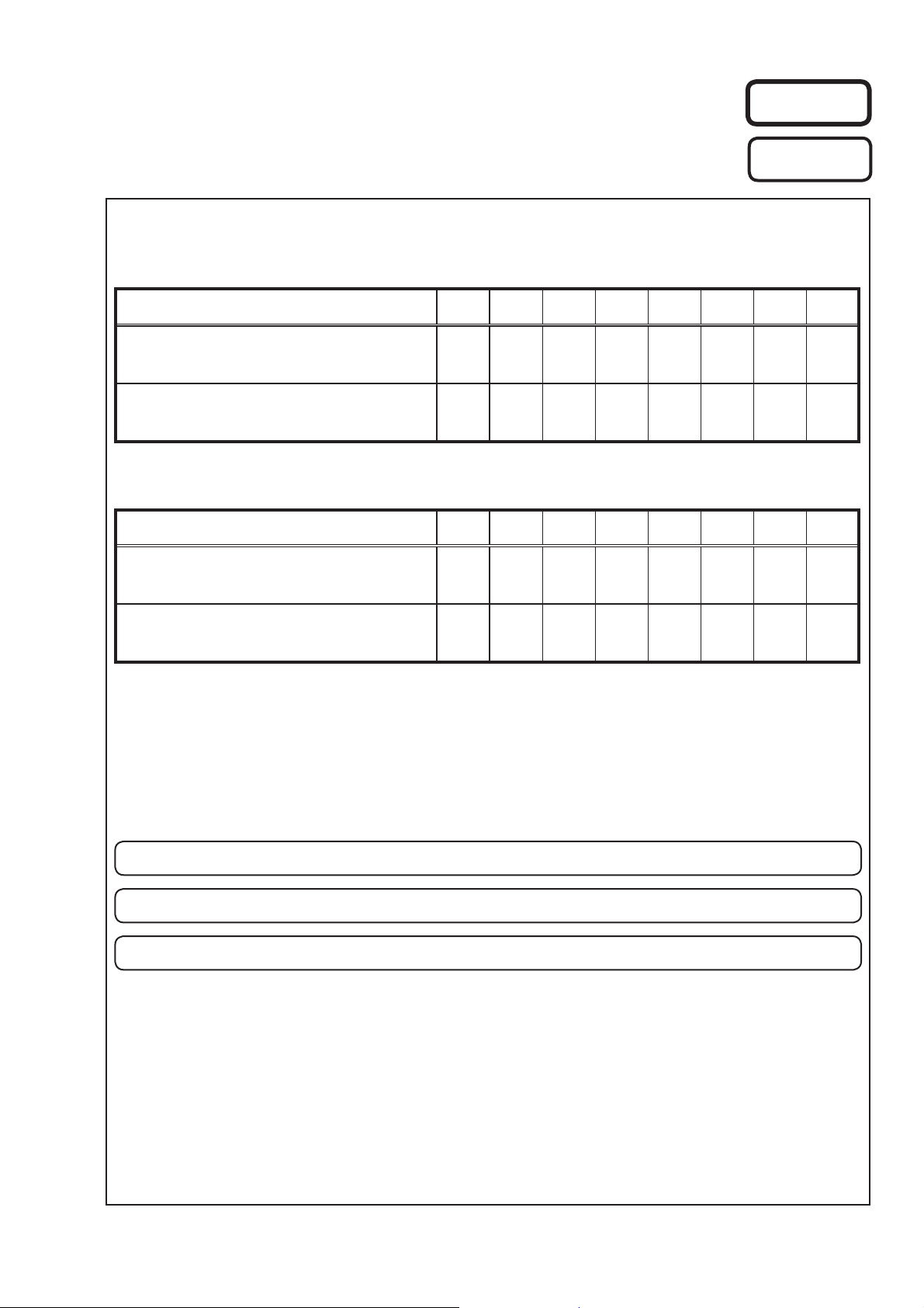
MODEL JP E3 E3B E2 EK EA E1 E1C
Ver. 3
Please refer to the
MODIFICATION NOTICE.
AVR-1311
AVR-391
MODEL JP E3 E3B E2 EK EA E1 E1C
DHT-1311XP
DHT-391XP
5.1CH HOME THEATER SYSTEM
33
33
AV SURROUND RECEIVER
3
33 3
s
For purposes of improvement, specifi cations and design are subject to change without notice.
•
Please use this service manual with referring to the operating instructions without fail.
•
Some illustrations using in this service manual are slightly different from the actual set.
•
e
D&M Holdings Inc.
S0141-0V03DM/DG1010
Copyright 2010 D&M Holdings Inc. All rights reserved.
WARNING: Violators will be prosecuted to the maximum extent possible.

SAFETY PRECAUTIONS
The following check should be performed for the continued protection of the customer and service technician.
LEAKAGE CURRENT CHECK
Before returning the unit to the customer, make sure you make either (1) a leakage current check or (2) a line to chassis
resistance check. if the leakage current exceeds 0.5 milliamps, or if the resistance from chassis to either side of the
power cord is less than 460 kohms, the unit is defective.
Be sure to test for leakage current with the AC plug in both polarities, in addition, in each power ON, OFF and STANDBY
mode, if applicable.
CAUTION
Please heed the points listed below during servicing and inspection.
◎Heed the cautions!
Spots requiring particular attention when servicing, such
as the cabinet, parts, chassis,etc., have cautions indicated
on labels. be sure to heed these causions and the
cautions indicated in the handling instructions.
◎Caution concerning electric shock!
(1) An AC voltage is impressed on this set, so touching
internal metal parts when the set is energized could
cause electric shock. Take care to avoid electric
shock, by for example using an isolating transformer
and gloves when servicing while the set is energized,
unplugging the power cord when replacing parts, etc.
(2) Tere are high voltage parts inside. Handle with extra
care when the set is energized.
◎ Caution concerning disassembly and
assembly!
Through great care is taken when manufacturing parts
from sheet metal, there may in some rare cases be burrs
on the edges of parts which could cause injury if fi ngers
are moved across them. Use gloves to protect your hands.
◎Only use designated parts!
The set’s parts have specific safety properties (fire
resistance, voltage resistance, etc.). For replacement
parts, be sure to use parts which have the same
poroperties. In particular, for the important safety parts
that are marked z on wiring diagrams and parts lists, be
sure to use the designated parts.
◎ Be sure to mount parts and arrange the wires
as they were originally!
For safety seasons, some parts use tape, tubes or other
insulating materials, and some parts are mounted away
from the surface of printed circuit boards. Care is also
taken with the positions of the wores omsode amd clamps
are used to keep wires away from heating and high
voltage parts, so be sure to set everything back as it was
originally.
◎Inspect for safety after servicing!
Check that all screws, parts and wires removed or
disconnected for servicing have been put back in their
original positions, inspect that no parts around the area
that has been serviced have been negatively affected,
conduct an inslation check on the external metal
connectors and between the blades of the power plug,
and otherwise check that safety is ensured.
(Insulation check procedure)
Unplug the power cord from the power outlet, disconnect
the antenna, plugs, etc., and turn the power switch on.
Using a 500V insulation resistance tester, check that the
inplug and the externally exposed metal parts (antenna
terminal, headphones terminal, input terminal, etc.) is
1MΩ or greater. If it is less, the set must be inspected and
repaired.
CAUTION
Concerning important safety
parts
Many of the electric and structural parts used in the set
have special safety properties. In most cases these
properties are difficult to distinguish by sight, and using
replacement parts with higher ratings (rated power and
withstand voltage) does not necessarily guarantee that
safety performance will be poreserved. Parts with safety
properties are indicated as shown below on the wiring
diagrams and parts lists is this service manual. Be sure to
replace them with parts with the designated part number.
(1) Schematic diagrams ……Indicated by the z mark.
(2) Parts lists ……Indicated by the z mark.
Using parts other than the designated
parts could result in electric shock, fi res
or other dangerous situations.
2
NOTE FOR SCHEMATIC DIAGRAM
WARNING:
Parts marked with this symbol z have critical characteristics. Use ONLY replacement parts recommended by the manufacture
CAUTION:
Before returning the unit to the customer, make sure you make either (1) a leakage current check or (2) a line to chassis resistance check. If the
leakage current exceeds 0.5 milliamps, or if the resistance from chassis to either side of the power cord is less than 460 kohms, the unit is defective.
WARNING:
DO NOT return the unit to the customer until the problem is located and corrected.
NOTICE:
ALL RESISTANCE VALUES IN OHM. k=1,000 OHM / M=1,000,000 OHM
ALL CAPACITANCE VALUES IN MICRO FARAD. P=MICRO-MICRO FARAD EACH VOLTAGE AND CURRENT ARE MEASURED AT NO SIGNAL
INPUT CONDITION. CIRCUIT AND PARTS ARE SUBJECT TO CHANGE WITHOUT PRIOR NOTICE.
r.
NOTE FOR PARTS LIST
Parts for which «nsp» is indicated on this table cannot be supplied.
1.
When ordering of part, clearly indicate «1» and «I» (i) to avoid mis-supplying.
2.
3.
Ordering part without stating its part number can not be supplied.
4.
Part indicated with the mark «★» is not illustrated in the exploded view.
5.
Not including General-purpose Carbon Film Resistor in the P.W.Board parts list. (Refer to the Schematic Diagram for those parts.)
6.
Not including General-purpose Carbon Chip Resistor in the P.W.Board parts list. (Refer to the Schematic Diagram for those parts.)
WARNING:
● Resistors
Ex.: RN
* Resistance
Capacitors
●
Ex.: CE
* Capacity (electrolyte only)
* Capacity (except electrolyte)
・ When the dielectric strength is indicated in AC,»AC» is included after the dieelectric strength value.
Parts marked with this symbol z have critical characteristics. Use ONLY replacement parts recommended by the manufacturer.
14K
Type
RD : Carbon
RC : Composition
RS : Metal oxide film
RW: winding
RN : Metal film
RK : Metal mixture
: Units: ohm
Type
CE : Aluminum foil
electrolytic
CA : Aluminium solid
electrolytic
CS : Tantalum electrolytic
CQ : Film
CK : Ceramic
CC : Ceramic
CP : Oil
CM: Mica
CF : Metallized
CH : Metallized
・ Units:μF.
・ Units:pF
Shape
and performance
2
Indicates number of zeros after effective number.
2-digit effective number.
1-digit effective number.
2-digit effective number, decimal point indicated by R.
04W
Shape
and performance
2
Indicates number of zeros after effective number.
2-digit effective number.
2
Indicates number of zeros after efective number. (More than 2)
2-digit effective number.
2E
Power
2B : 1/8 W
2E : 1/4 W
2H : 1/2 W
3A : 1 W
3D : 2 W
3F : 3 W
3H : 5 W
1800ohm=1.8kohm1 8
1.2ohm1 R 2
1H
Dielectric
strength
0J : 6.3 V
1A : 10 V
1C : 16 V
1E : 25 V
1V : 35 V
1H : 50 V
2A : 100 V
2B : 125 V
2C : 160 V
2D : 200 V
2E : 250 V
2H : 500 V
2J : 630 V
2200μF2 2
2200pF=0.0022μF2 2
182
Resistance
F:±1%
G:±2%
J:±5%
K:±10%
M:±20%
3R2
CapacityMAllowable
G
Allowable
error
P : Pulse-resistant type
NL : Low noise type
NB : Non-burning type
FR : Fuse-resistor
F : Lead wire forming
error
F:±1%
G:±2%
J:±5%
K:±10%
M:±20%
Z:±80%
: — 20%
P : +100%
C:±0.25pF
D:±0.5pF
= : Others
FR
Others
BP
Others
HS : High stability type
BP : Non-polar type
HR : Ripple-resistant type
DL : For change and discharge
HF : For assuring high requency
U : UL part
C : CSA part
W : UL-CSA part
F : Lead wire forming
2
・ Units:μF.
1
・ Units:pF
2.2μF2 R
1-digit effective number.
2-digit effective number, decimal point indicated by R
220pF2 2
Indicates number of zeros after effective numver. (0 or 1)
2-digit effective number.
3
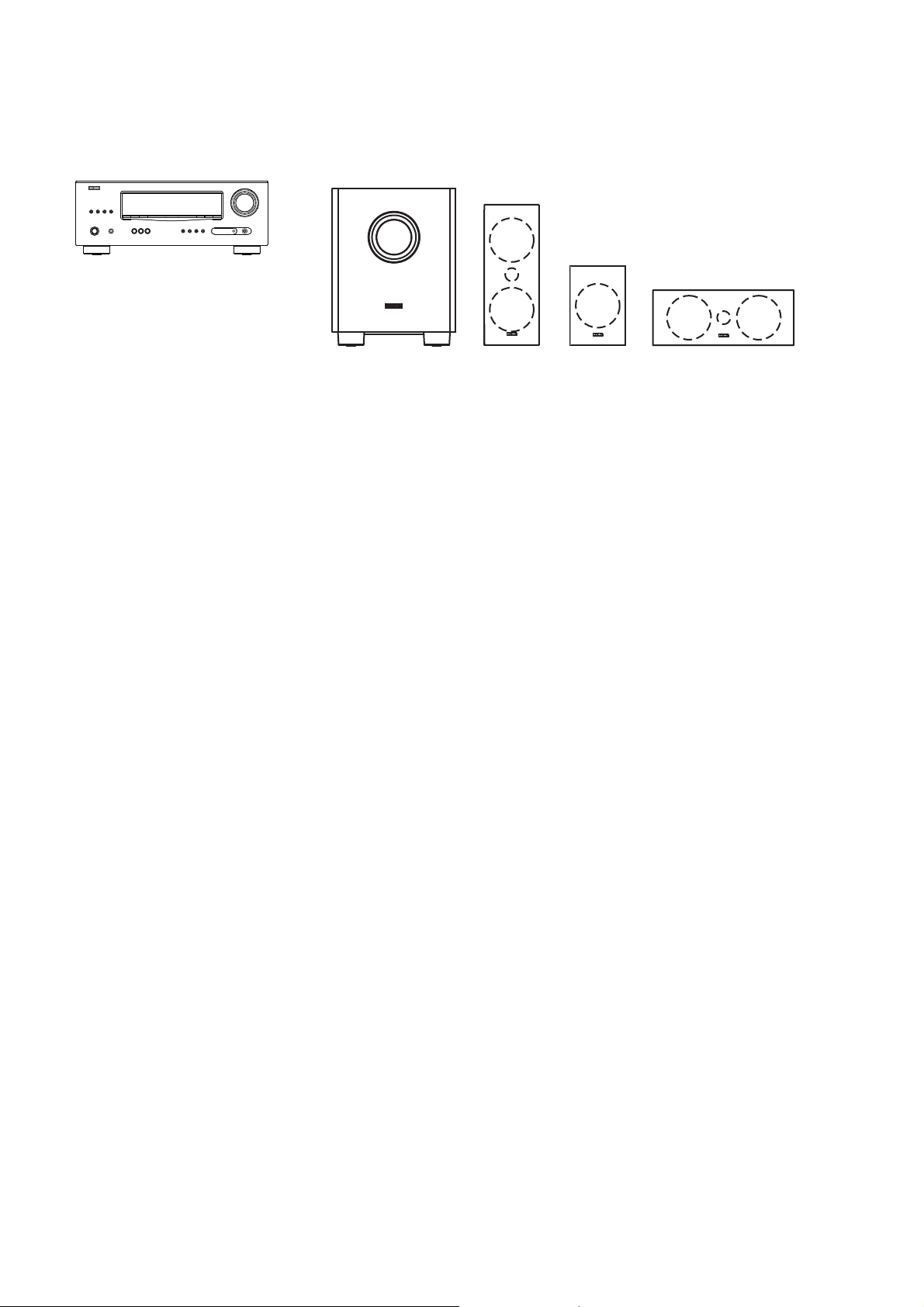
SYSTEM CONFIGURATION
• AVR-1311
• AVR-391
• DHT-1311XP (AVR-1311 + SYS-391HT)
• DHT-391XP (AVR-391 + SYS-391HT)
SYS-391HT : Refer to page 104-113 for the service manual.
TECHNICAL SPECIFICATIONS
n Audio Section
• Power amplifi er
Rated output :
Front :
75 W + 75 W (8 Ω, 20 Hz – 20 kHz with 0.08 % T.H.D.)
110 W + 110 W (6 Ω, 1 kHz with 0.7 % T.H.D.)
Center :
75 W (8 Ω, 20 Hz – 20 kHz with 0.08 % T.H.D.)
110 W (6 Ω, 1 kHz with 0.7 % T.H.D.)
Surround :
75 W + 75 W (8 Ω, 20 Hz – 20 kHz with 0.08 % T.H.D.)
110 W + 110 W (6 Ω, 1 kHz with 0.7 % T.H.D.)
Output connectors : 6 – 16 Ω
• Analog
Input sensitivity/Input impedance : 200 mV/47 kΩ
Frequency response: 10 Hz – 100 kHz — +1, –3 dB (DIRECT mode)
S/N : 98 dB (IHF–A weighted, DIRECT mode)
n Video Section
• Standard video connectors
Input/output level and impedance : 1 Vp-p, 75 Ω
Frequency response : 5 Hz – 10 MHz — +1, –3 dB
• Color component video connector
Input/output level and impedance :
Y (brightness) signal — 1 Vp-p, 75 Ω
B / CB signal — 0.7 Vp-p, 75 Ω
P
R / CR signal — 0.7 Vp-p, 75 Ω
P
Frequency response : 5 Hz – 10 MHz — +1, –3 dB
SYS-391HT
DSW-391 SC-C391SC-F391(x2) SC-R391(x2)
n Tuner section
[FM](Note: μV at 75 Ω, 0 dBf = 1 x 10
Receiving Range (for 391E3,391E3B) :
[FM] 87.5 MHz – 107.9 MHz
Receiving Range (for 1311E2,1311E1C,391EA) :
[FM] 87.5 MHz – 108.0 MHz
Usable Sensitivity :
[FM]1.2 μV (12.8 dBf)
50 dB Quieting Sensitivity :
[FM]MONO 2.8 μV (20.2 dBf)
S/N (IHF-A) :
[FM]MONO 70 dB
STEREO 67 dB
Total harmonic Distortion (at 1 kHz) :
[FM]MONO 0.7 %
STEREO 1.0 %
[AM]520 kHz – 1710 kHz
[AM]522 kHz – 1611 kHz
[AM]18 μV
n General
Power supply (for 391E3,391E3B) : AC 120 V, 60 Hz
(for 1311E2,391EA) : AC 230 V, 50 Hz
(for 1311E1C) : AC 220 V, 50 Hz
Power consumption :
330 W
Less than 0.5 W (Standby)
Maximum external dimensions :
435 (W) x 166 (H) x 381 (D) mm
Weight : 9.2 kg
n Remote Control Unit (RC-1149)
Batteries : R03/AAA Type (two batteries)
Maximum external dimensions : 50 (W) x 211 (H) x 22 (D) mm
Weight : 110 g (including batteries)
–15
W)
s
s
4
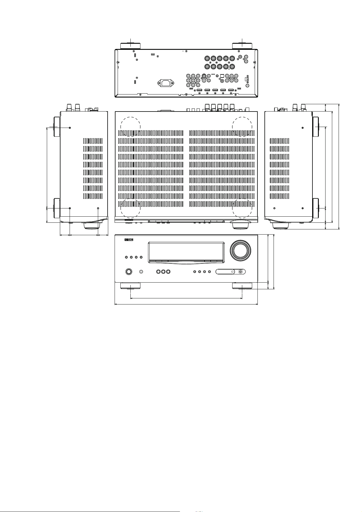
DIMENSION
22.2
245.0
43.5
30.0 30.5
86.0
340.0
435.0
248.0
43.5
20.7
146.5
166.5
20.0
The illustration is AVR-1311 model.
338.5
381.4
5
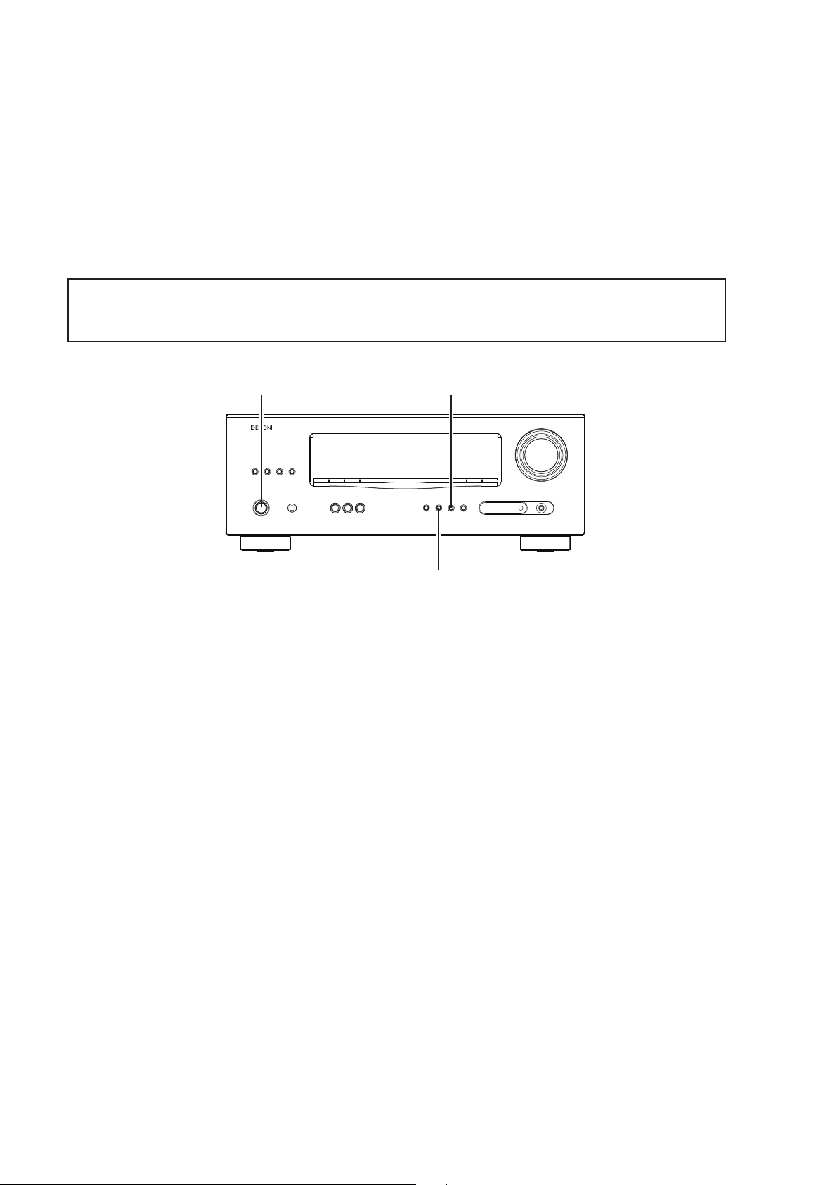
CAUTION IN SERVICING
Initializing AV SURROUND RECEIVER
AV SURROUND RECEIVER initialization should be performed when the μcom, peripheral parts of μcom, and Digital
P.W.B. are replaced.
1. Turn off the power using ON/STANDBY button.
2. Press ON/STANDBY button while simultaneously pressing SURROUND MODE 0 and SURROUND MODE
buttons.
3. Check that the entire display is fl ashing with an interval of about 1 second, and release your fi ngers from the 2
buttons and the microprocessor will be initialized.
Note: •If step 3 does not work, start over from step 1.
All user settings will be lost and this factory setting will be recovered when this initialization mode.
•
So make sure to memorize your setting for restoring after the initialization.
1
ON/STANDBY
SURROUND MODE 1
SURROUND MODE 0
Service Jigs
When you update the fi rmware, you can use the following
JIG (RS232C to internal connector conversion adapter with 4P FFC cable kit ).
Please order to Denon Offi cial Service Distributor in your region if necessary.
8U-210100S : WRITING KIT : 1 Set
606050028012P
(Refer to «VERSION UPGRADE PROCEDURE OF FIRMW
: 7P FFC(1.0) L-240 : 1 Set
ARE».)
6
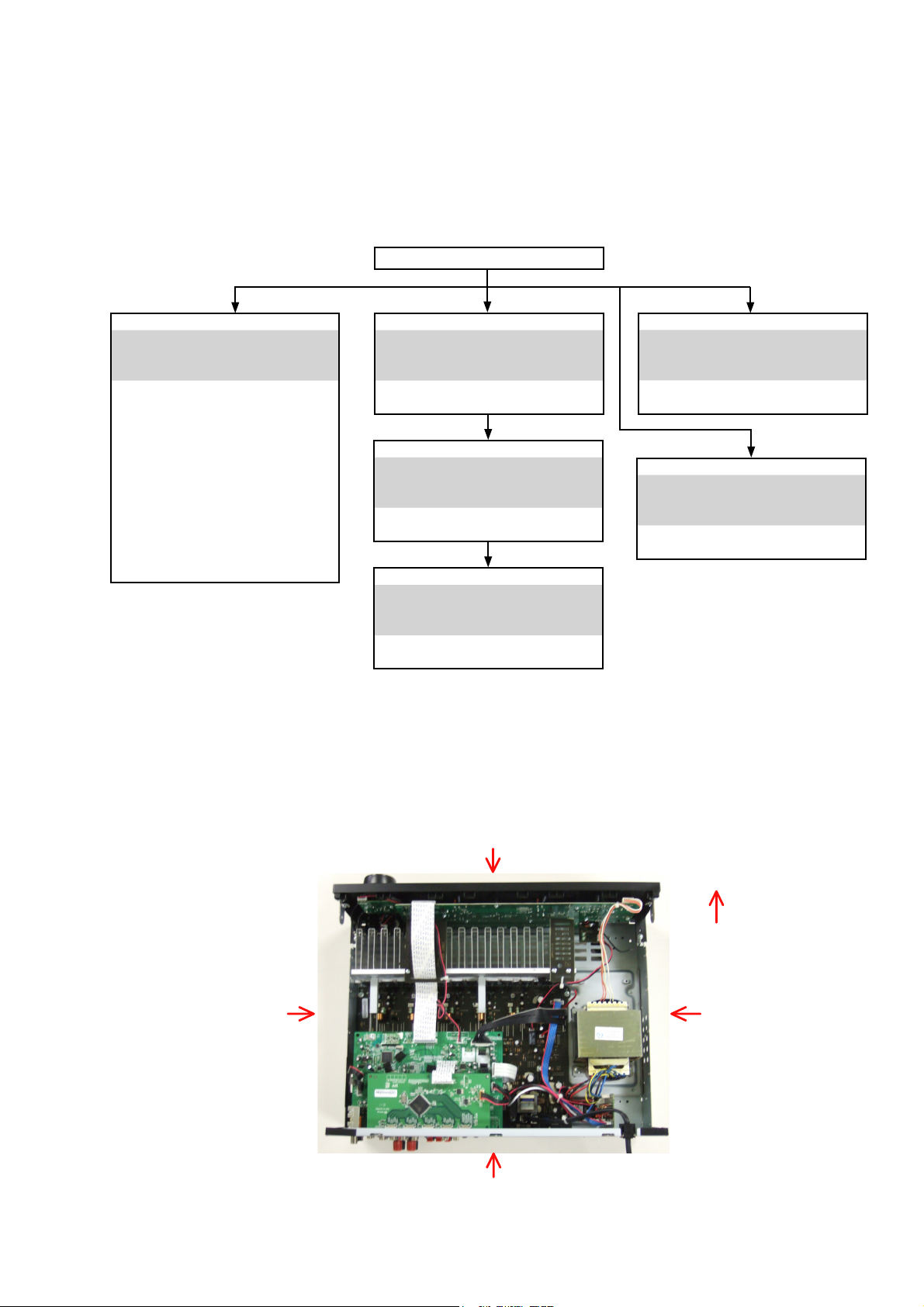
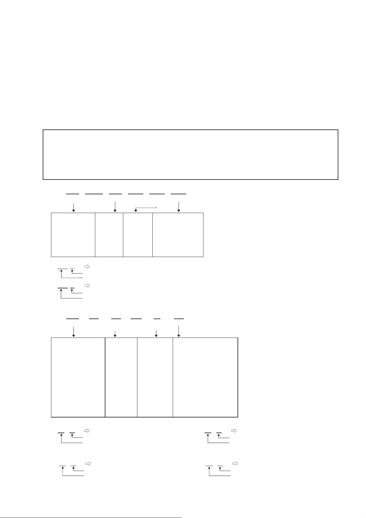
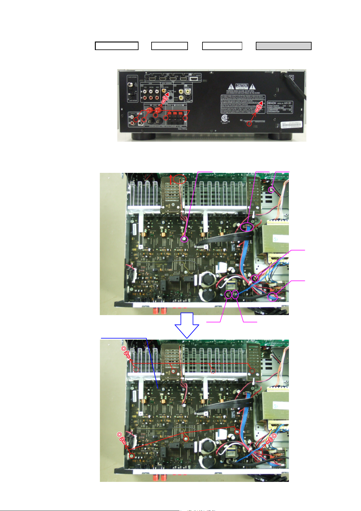
DISASSEMBLY
• Disassemble in order of the arrow of the fi gure of following fl ow.
• In the case of the re-assembling, assemble it in order of the reverse of the following fl ow.
• In the case of the re-assembling, observe «attention of assembling» it.
• If wire bundles are untied or moved to perform adjustment or parts replacement etc., be sure to rearrange them neatly
as they were originally bundled or placed afterward.
Otherwise, incorrect arrangement can be a cause of noise generation.
TOP COVER
FRONT PANEL ASSY
Refer to «DISASSEMBLY
1. FRONT PANEL ASSY»
and «EXPLODED VIEW»
AUX UNIT
(Ref. No. of EXPLODED VIEW : C1)
PHONE UNIT
(Ref. No. of EXPLODED VIEW : C2)
VOLUME UNIT
(Ref. No. of EXPLODED VIEW : C3)
HEADPHONE UNIT
(Ref. No. of EXPLODED VIEW : C8)
POWER UNIT
(Ref. No. of EXPLODED VIEW : C9)
FRONT UNIT
(Ref. No. of EXPLODED VIEW : C10)
HDMI UNIT
Refer to «DISASSEMBLY
2. HDMI UNIT»
and «EXPLODED VIEW»
HDMI UNIT
(Ref. No. of EXPLODED VIEW : C7)
INPUT UNIT
Refer to «DISASSEMBLY
3. INPUT UNIT»
and «EXPLODED VIEW»
INPUT UNIT
(Ref. No. of EXPLODED VIEW : C6)
RADIATOR ASSY
Refer to «DISASSEMBLY
4. RADIATOR ASSY»
and «EXPLODED VIEW»
MAIN UNIT
(Ref. No. of EXPLODED VIEW : C5)
REGULATOT UNIT
(Ref. No. of EXPLODED VIEW : C13)
POWER TRANS
(Ref. No. of EXPLODED VIEW : C14)
POWER UNIT
Refer to «DISASSEMBLY
5. POWER UNIT»
and «EXPLODED VIEW»
POWER TRANS
Refer to «DISASSEMBLY
6. POWER TRANS «
and «EXPLODED VIEW»
About the photos used for descriptions in the DISASSEMBLY» section.
• The direction from which the photographs used herein were photographed is indicated at «Direction of photograph: ***»
at the left of the respective photographs.
• Refer to the table below for a description of the direction in which the photos were taken.
• Photographs for which no direction is indicated were taken from above the product.
The viewpoint of each photograph
(Photografy direction)
[View from above]
Direction of photograph: C
Direction of photograph: B
Front side
Direction of photograph: D
Direction of photograph: A
7

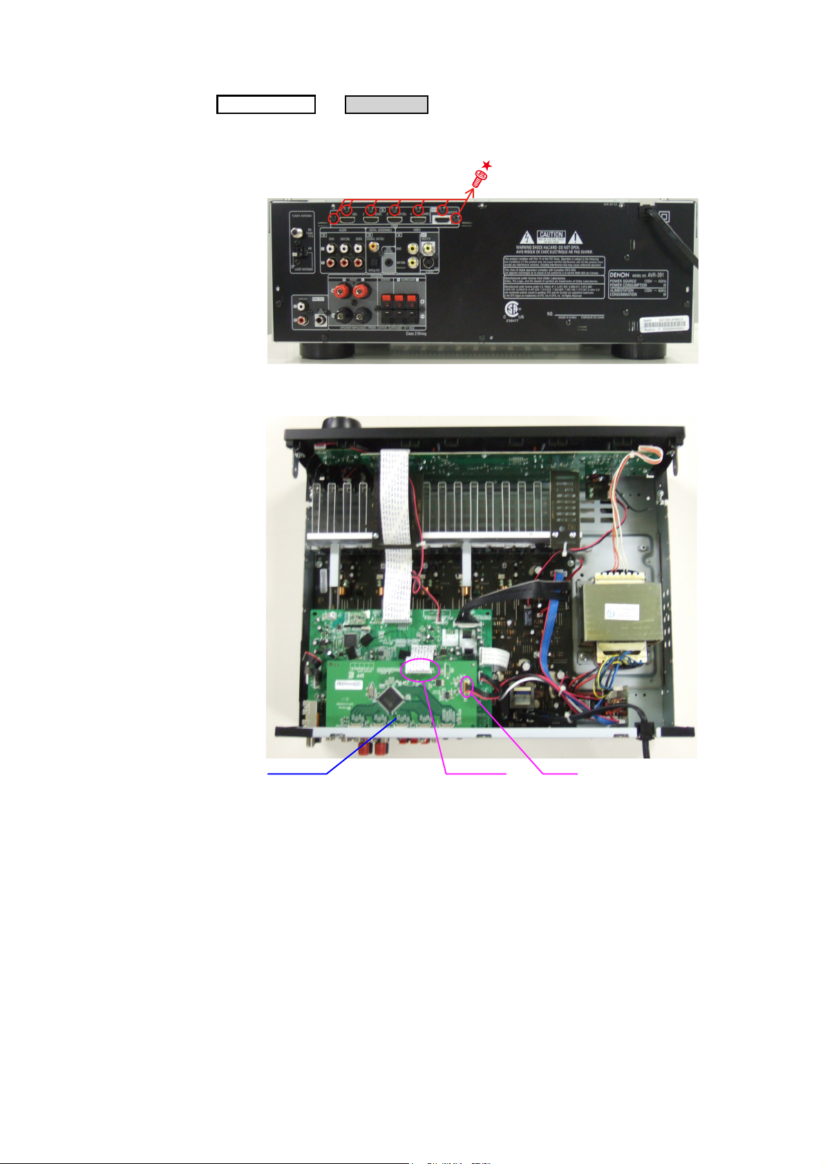
1. FRONT PANEL ASSY
Proceeding :
(1) Remove the screws.
View from bottom
(2) Cut the wire clamp band, then disconnect the connector wires and FFC cable. Remove the screws.
TOPCOVER
FRONT PANEL ASSY
FRONT PANEL ASSY
→
FFC cable
CN44
cut
CN209
cut
(3) Remove the screws.
Please refer to «EXPLODED VIEW» for the disassembly method of each P.W.B included in FRONT PANEL ASSY.
CN71
8
WIRE SUPPORT UNIT
2. HDMI UNIT
Proceeding :
(1) Remove the screws.
Direction of photograph: A
(2) Disconnect the connector wire and FFC cable.
TOPCOVER
HDMI UNIT
→
HDMI UNIT
CN12FFC cable
9
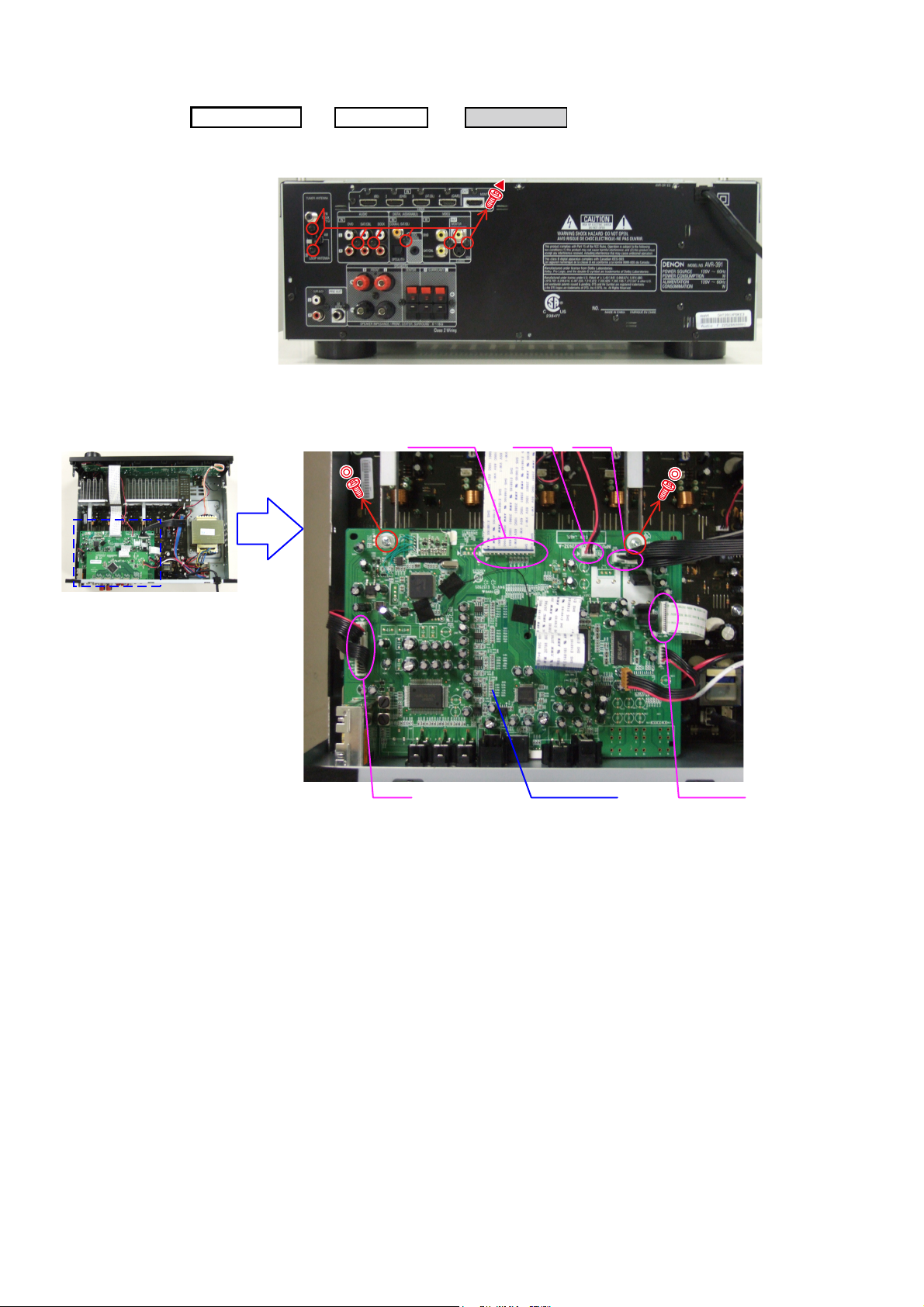
3. INPUT UNIT
Proceeding :
(1) Remove the screws.
Direction of photograph: A
(2) Disconnect the connector wires and FFC cables, then remove the screws.
TOPCOVER
HDMI UNIT
→
FFC cable
INPUT UNIT
→
CN71 CN43
CN42
INPUT UNIT
FFC cable
10
4. RADIATOR ASSY
Proceeding :
(1) Remove the screws.
Direction of photograph: A
(2) Disconnect the connector wires, then remove the screws.
TOPCOVER
HDMI UNIT
→
→
INPUT UNIT
CN71 CN44
RADIATOR ASSY
→
CN46
RADIATOR ASSY
CN45
CN41
CN47 CN48
11

(3) Remove the RADIATOR ASSY from the main unit.
Direction of photograph: C
Please refer to «EXPLODED VIEW» for the disassembly method of each P.W.B included in RADIATOR ASSY.
5. POWER UNIT
Proceeding :
Please refer to «EXPLODED VIEW» for the disassembly method of POWER UNIT.
TOPCOVER
POWER UNIT
→
6. POWER TRANS
Proceeding :
Please refer to «EXPLODED VIEW» for the disassembly method of POWER TRANS.
CABINET TOP
TRANS MAIN
→
12
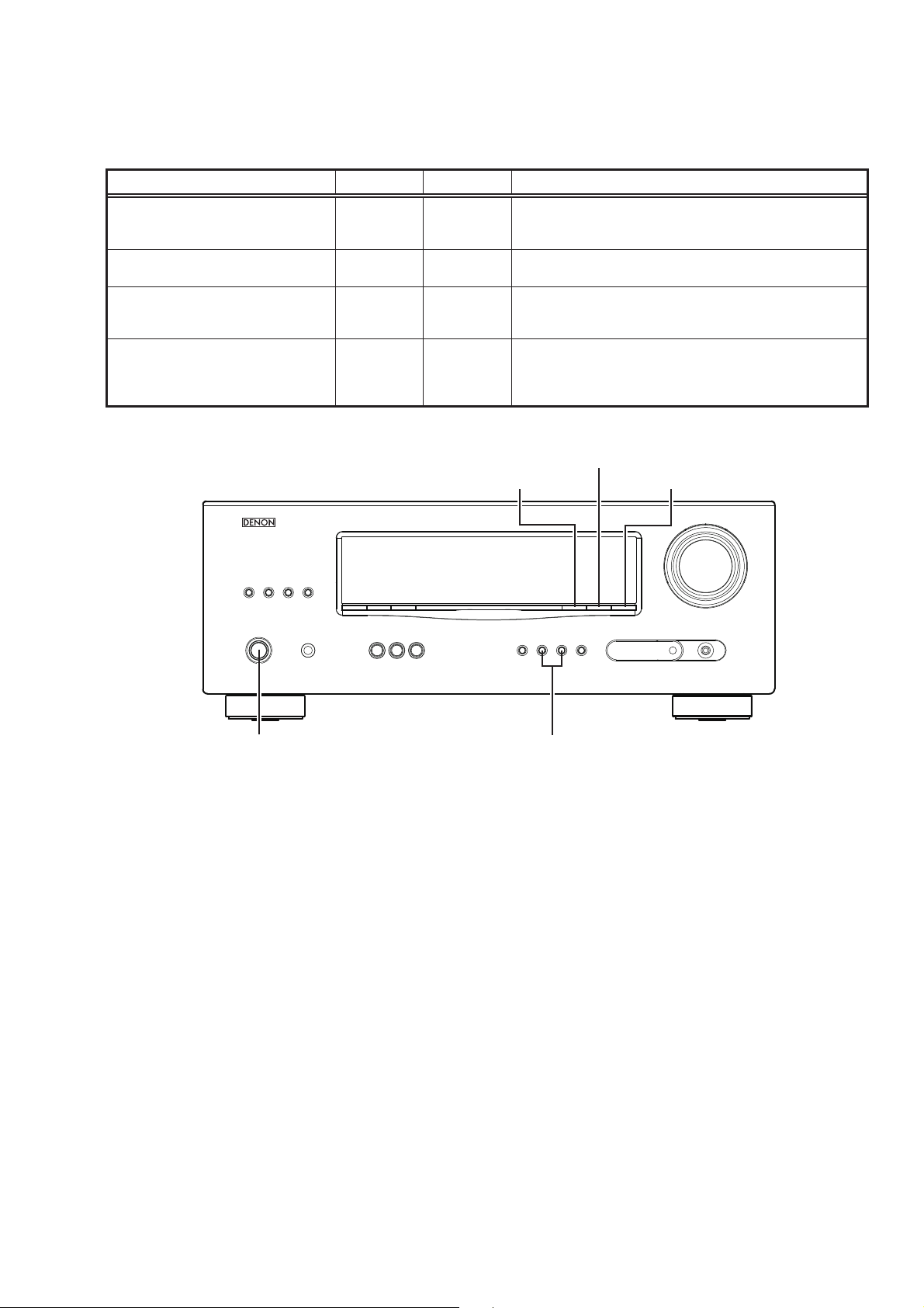
SPECIAL MODE
Special mode setting button
Press the ON/STANDBY button to turn on while pressing both buttons A and B at the same time.
b
Mode Button A Button B Contents
Firmware versions such as Main, DSP are displayed in the FL
μcom/DSP Version display mode STATUS DIMMER
Initialization mode
Mode for switching tuner frequency step
Mode for preventing remote control
acceptance
SURROUND
MODE
SURROUND
MODE
SURROUND
MODE
0
0
0
SURROUND
MODE
RESTORER
STATUS
display. Errors are displayed when they occur.
(Refer to page 14.)
Backup data initialization is carried out. (Refer to page 6.)
1
—E2 model only—Change tuner frequency step to AM9k/FM50kHz STEP or
AM:10k/FM:200kHz.
Operations using remote control are rejected.
«REMOTE LOCK:ON» is displayed in FL display.
(Mode cancellation: Turn off power and execute the same
button operations as when performing setup.)
DIMMER
RESTORER STATUS
ON/STANDBY
SURROUND
0 MODE 1
13
1. μcom/DSP Version display mode
1.1. Operation specifi cations
μcom/DSP version display mode:
When started up, the version information is displayed.
Starting up:
With the «DIMMER» and «STATUS» buttons pressed, press the «ON/STANDBY» button to turn the power on.
Now, press the «STATUS» button to the display the 2nd item information on the FL Display.
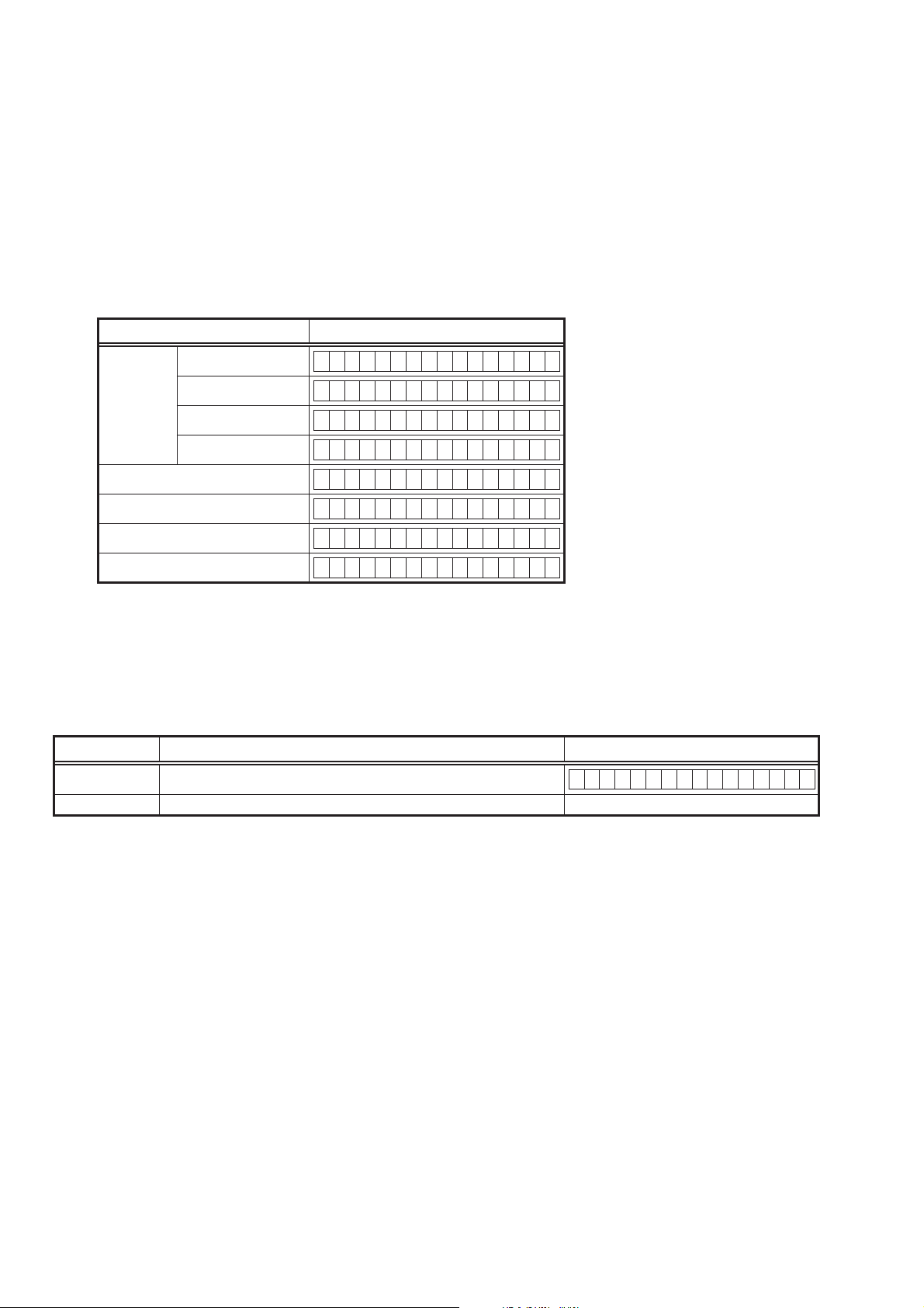
1.2. Display Order
Model name → Main-μcom version → DSP version → iPod Dock version (Connecting iPod Dock)
Display State
AVR-391 E3 model
AVR-1311 E2 model
Model name
AVR-391 EA model
AVR-1311 E1C model
Main-μcom version
DSP version
iPod Dock (ASD-1R/11R)
iPod Dock (ASD-3/51)
Cleared of mode:
Press the «ON/STANDBY» button to turn the power off.
AVR391 E3
AVR1311 E2
AVR391 EA
AVR1311 E1C
Main **.**
DSP.*.*.*
Dock Ver :**.**
Dock :I********
1.3. Error display
See the following table for each «Error information» display and its contents (status).
Condition — State
DSP NG When DSP boot, executing DSP reset makes to becomes error.
DSP OK (No error display, version display only)
DSP ERROR 01
14
ABOUT REPLACE THE MICROPROCESSOR WITH A NEW ONE
When replaced of the U-PRO (Microprocessor) or the Flash ROM, conrm contents of the following.
PWB Name Ref. No. Description
DIGITAL IC91 T5CN5 B SOFTWARE: Main
DIGITAL IC82 ST25VF080B-50-4C-S2AF B SOFTWARE: DSP ROM
After
replaced
Remark
After replaced
A : Mask ROM (With software). No need write-in of software to the microprocessor.
B : Flash ROM (With software). Usually, no need write-in of software. But, when the software was updated, you should be
write-in of the new software to the microprocessor or ash ROM. Please check the software version.
C : Empty Flash ROM (Without software). You should be write-in of the software to the microprocessor or ash ROM.
Refer to «Update procedure» or «writing procedure», when you should be write-in the software.
VERSION UPGRADE PROCEDURE OF FIRMWARE
1. Preparations
-Before starting the operation-
(1) Personal Computer (Installed “BootTool_M330(Writing program).exe”).
(2) RS-232 cable (9P (Male), Straight).
(3) 8U-210100S Writing Kit.
(4) 606050028012P / 7P FFC(1.0) L=240.
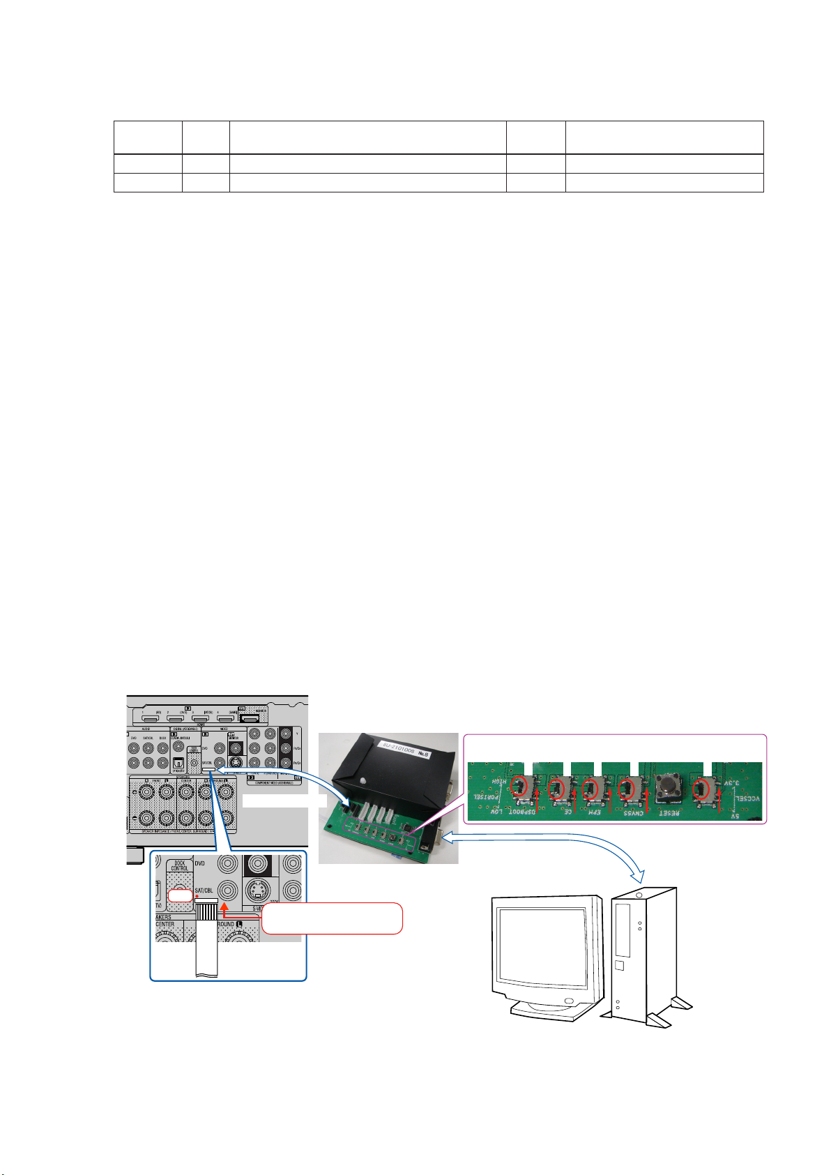
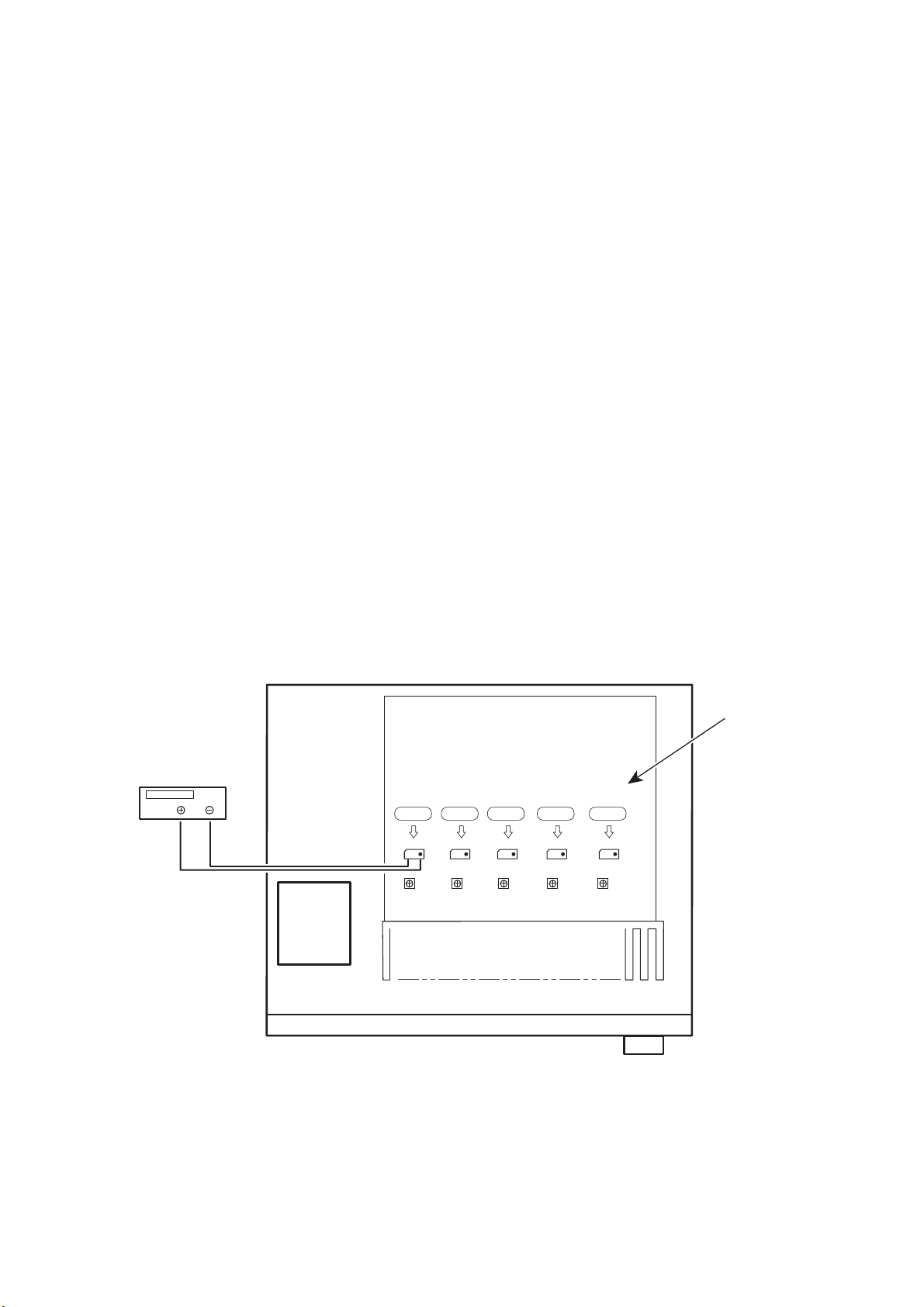
-Connection of the AV receiver-
(1) Conrm the power on/off switch of the AV receiver is turning off.
(2) Connect the update terminal of AV receiver with the “Writing Kit”.
(Refer to gure below for the connection of the 7P FFC cable.)
(3) Connect the RS-232C cable from PC with the “Writing Kit”.
7P FFC Cable
Writing Kit
1 pin
This side is contacts of
7P FFC Cable.
7P FFC Cable
S706-709 : HIGE
S709
S708
RS-232C Cable
S707
S706
S702 : 3.3V
S702
PC
15

2. UPDATE FIRMWARE
(1) Connect the update terminal of AV receiver with the “Writing Kit”.
(2) Set the switch of “Writing Kit» (Refer to the table below).
DSPBOOT CE EPM CNVSS
H H H H
(3) Press the «ON/STANDBY» button to turn the power on of AV receiver.
(4) Set the switch of “Writing Kit» (Refer to the table below).
DSPBOOT CE EPM CNVSS
H H L H
(5) Press the «RESET» switch of “Writing Kit».
(6) Run the “BootTool_M330(Writing program).exe” on desktop of PC.
(7) Click the “Connect” button.
«Connected» is displayed, it is OK.
16
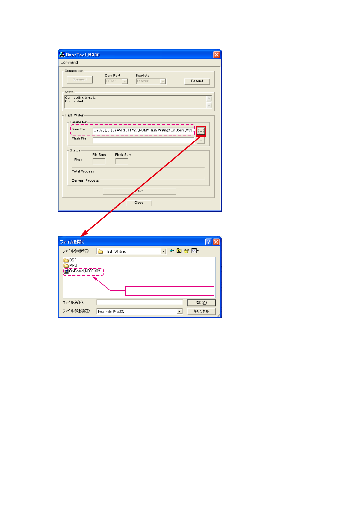
DSP SF1
(8) Choose Ram File(OnBoard_M330.s32).
Choose Ram File(OnBoard_M330.s32).
17
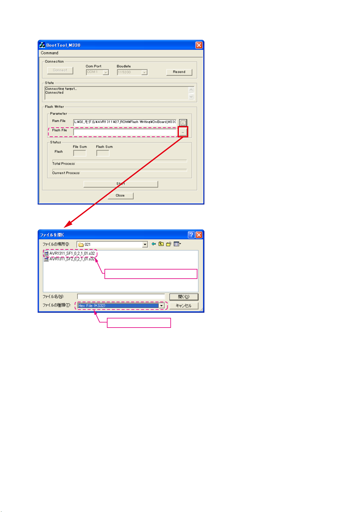
(9) Choose Flash File(DSP : SF1).
Choose «AVR1311_SF1_*_*_*_01.s32».
Choose «Hex File (*.S32)».
18
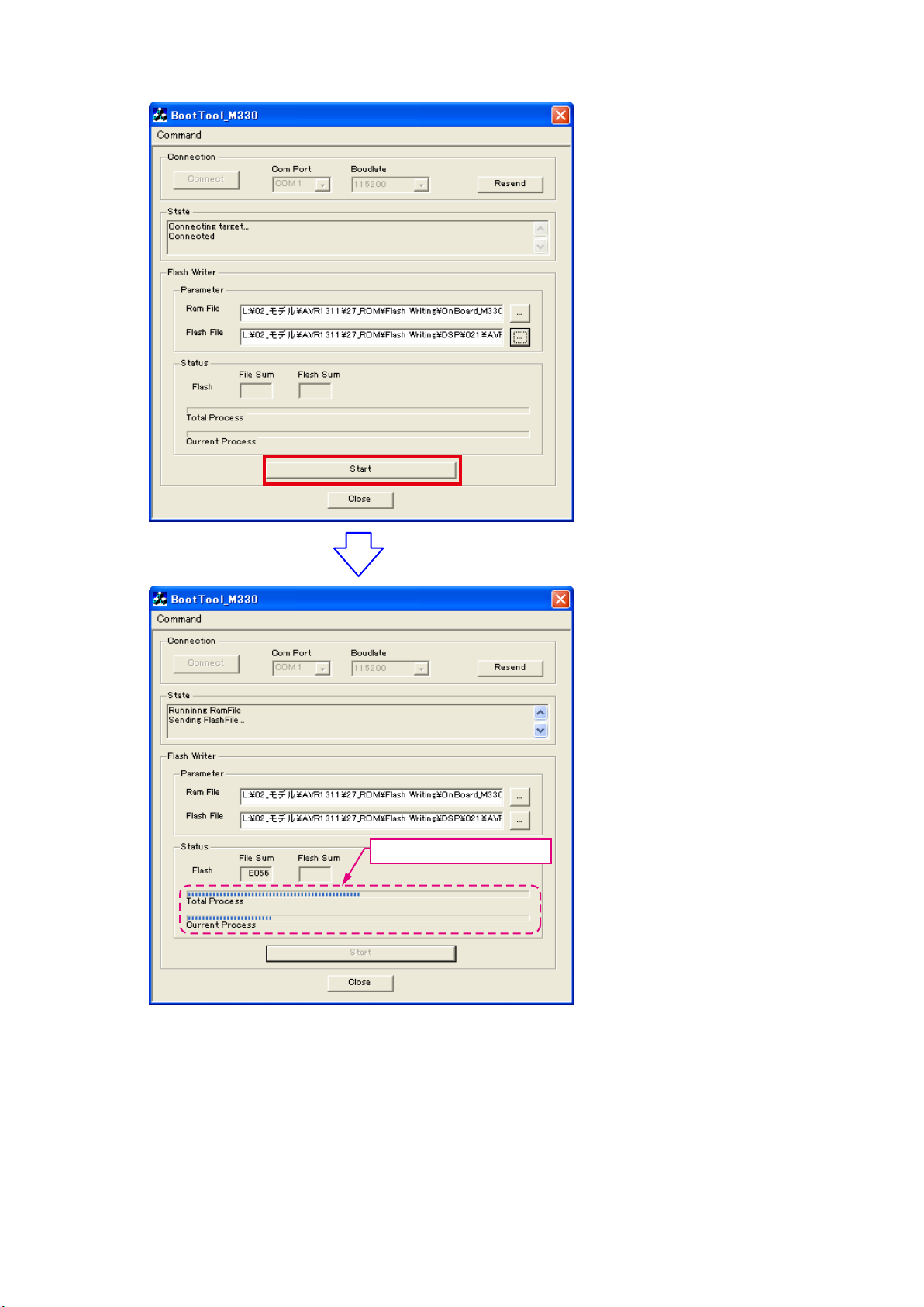
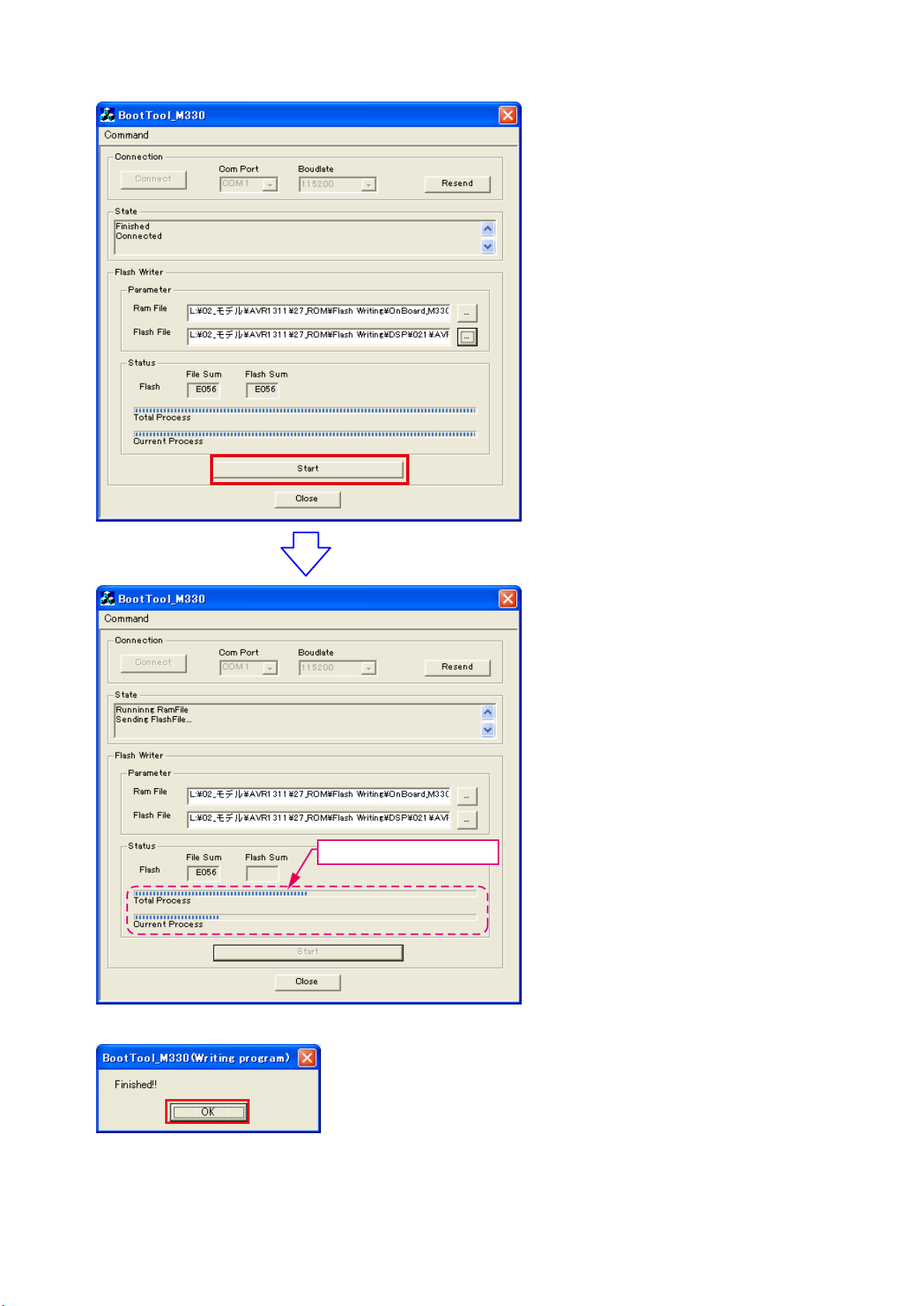
(10) Click the “Start” button.
The Setup Status bar appears.
19
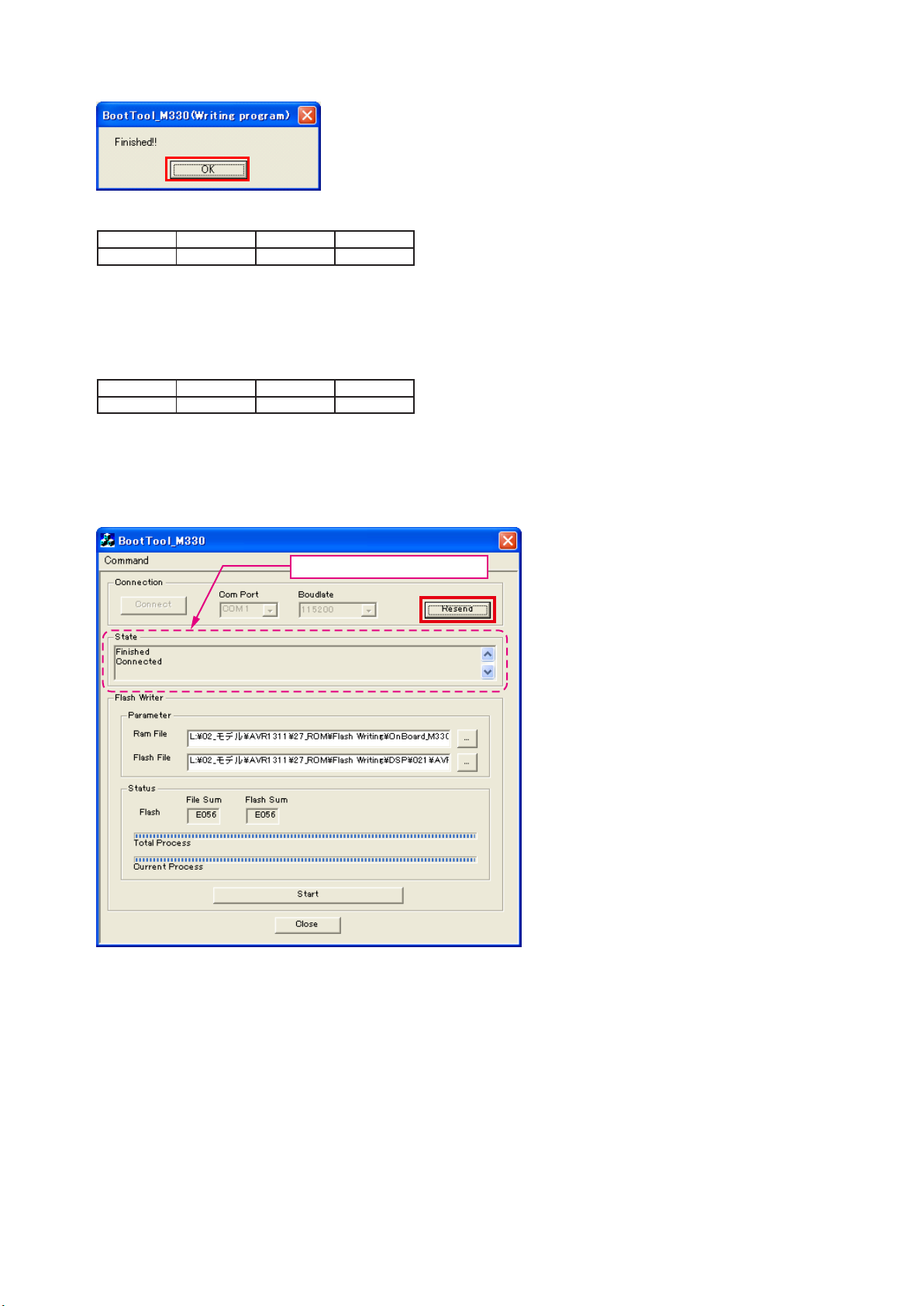
(11) «Finished!!» is displayed. Click the «OK»” button.
(12) Set the switch of “Writing Kit» (Refer to the table below).
DSPBOOT CE EPM CNVSS
H H H H
(13) Press the «RESET» switch of “Writing Kit».
(14) AV receiver is power on and starts update of DSP1.
(15) «Write Comleted» is displayed in the FL tube.
(16) Set the switch of “Writing Kit» (Refer to the table below).
DSPBOOT CE EPM CNVSS
H H L H
(17) Press the «RESET» switch of “Writing Kit».
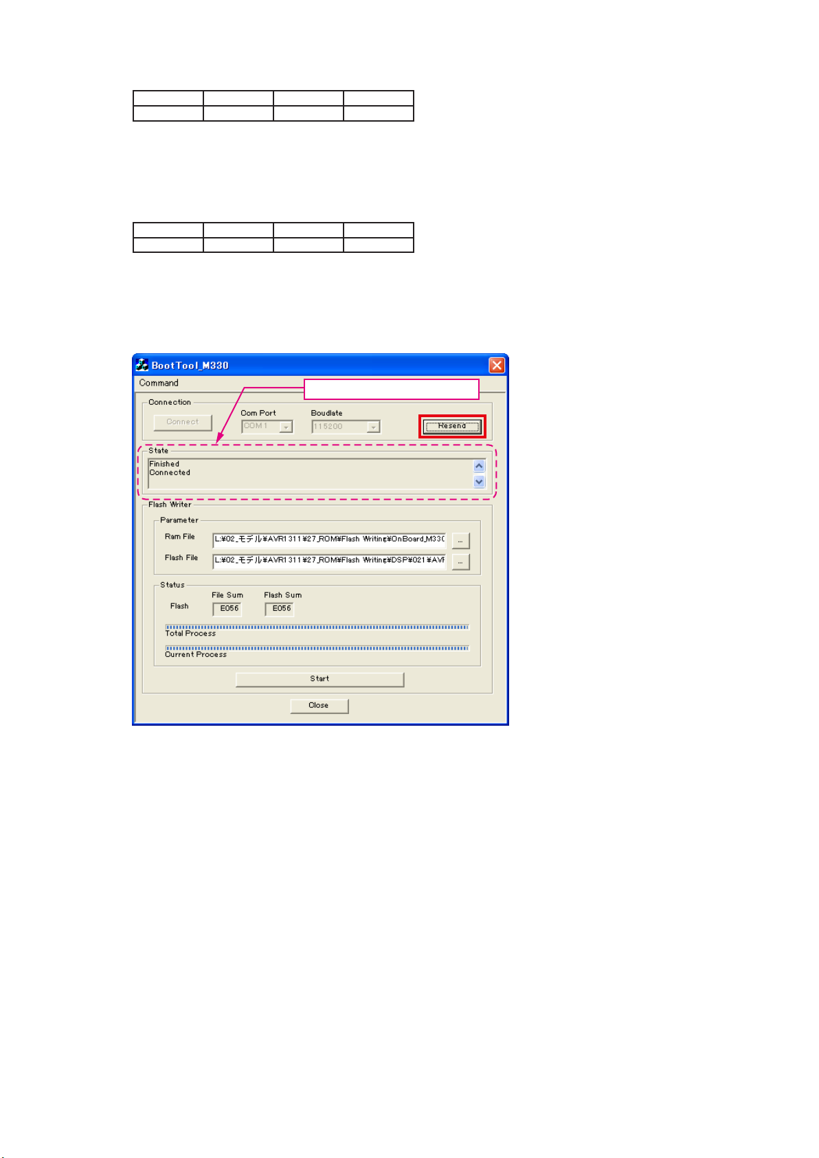
DSP SF2
(18) Click the “Resend” button.
«Connected» is displayed, it is OK.
20

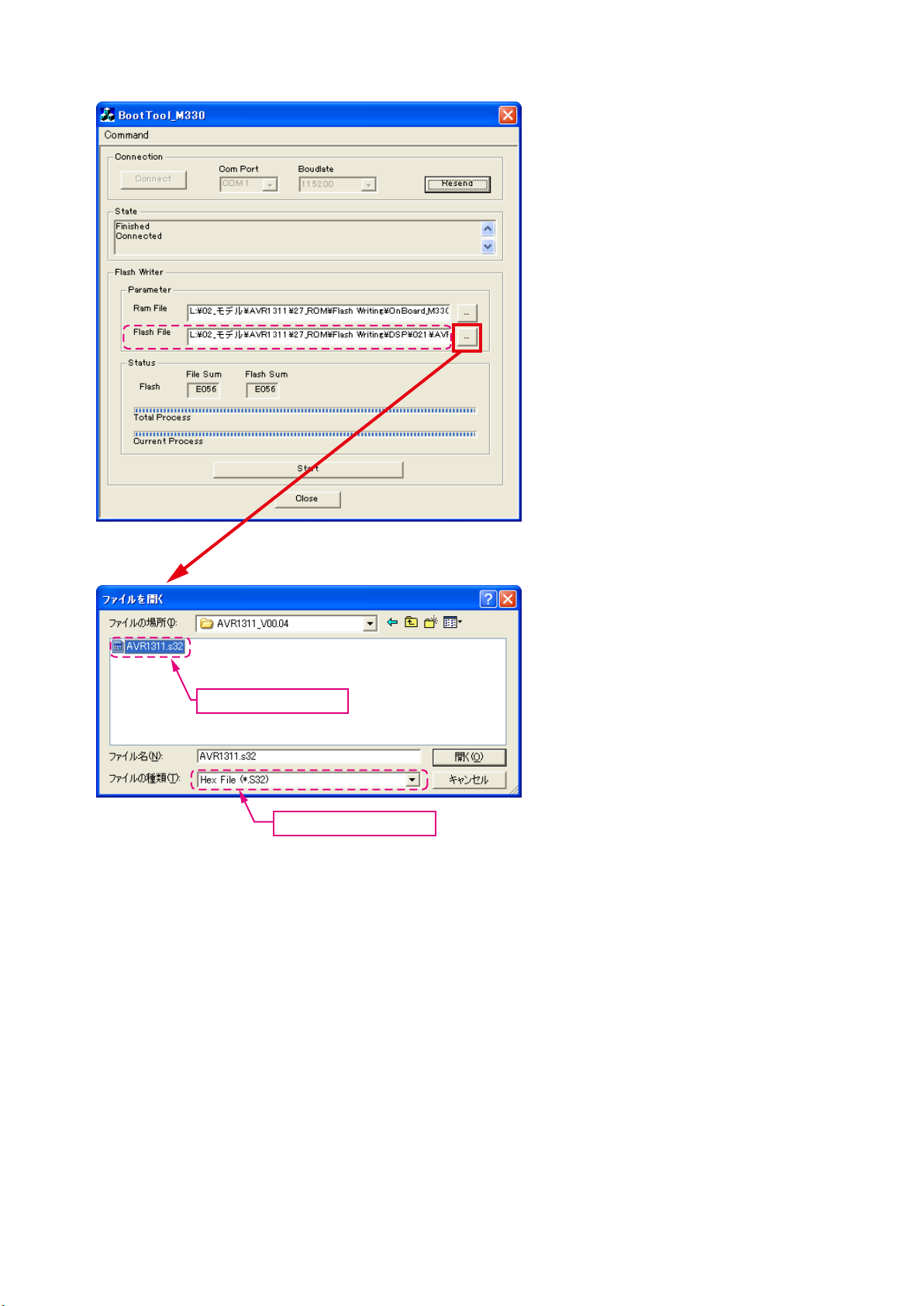
(19) Choose Flash File(DSP : SF2).
Choose «AVR1311_SF2_*_*_*_01.s32».
Choose «Hex File (*.S32)».
21
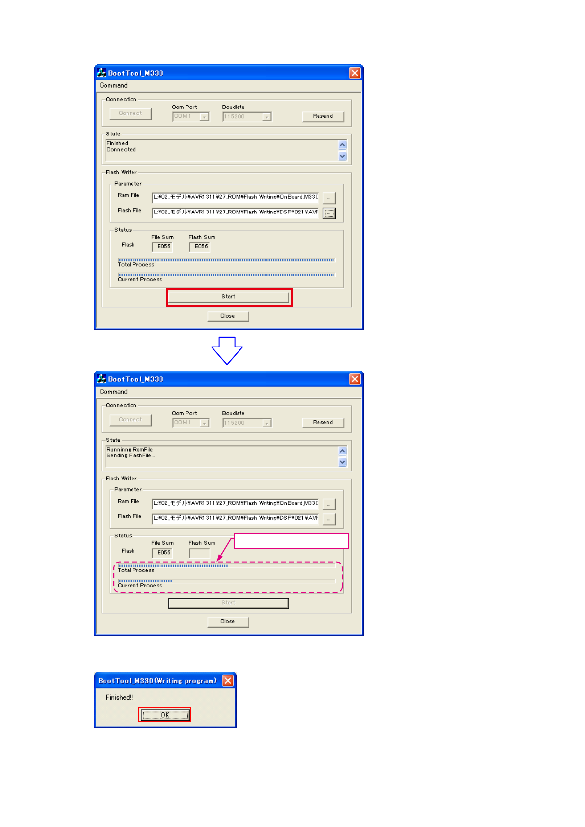
(20) Click the “Start” button.
The Setup Status bar appears.
(21) «Finished!!» is displayed. Click the «OK»” button.
22
(22) Set the switch of “Writing Kit» (Refer to the table below).
DSPBOOT CE EPM CNVSS
H H H H
(23) Press the «RESET» switch of “Writing Kit».
(24) AV receiver is power on and starts update of DSP2.
(25) «Write Comleted» is displayed in the FL tube.
(26) Set the switch of “Writing Kit» (Refer to the table below).
DSPBOOT CE EPM CNVSS
H H L H
(27) Press the «RESET» switch of “Writing Kit».
MAIN
(28) Click the “Resend” button.
«Connected» is displayed, it is OK.
23
(29) Choose Flash File(MAIN).
Choose «AVR1311.s32».
Choose «Hex File (*.S32)».
24
(30) Click the “Start” button.
The Setup Status bar appears.
(31) «Finished!!» is displayed. Click the «OK»” button.
25
(32) Set the switch of “Writing Kit» (Refer to the table below).
DSPBOOT CE EPM CNVSS
H H H H
(33) Press the «RESET» switch of “Writing Kit».
(34) Initializing.
1. Turn off the power using ON/STANDBY button.
2. Press ON/STANDBY button while simultaneously pressing SURROUND MODE
and SURROUND MODE
0
buttons.
3. Check that the entire display is ashing with an interval of about 1 second, and release your ngers from the 2
buttons and the microprocessor will be initialized.
Note: •If step 3 does not work, start over from step 1.
All user settings will be lost and this factory setting will be recovered when this initialization mode.
•
So make sure to memorize your setting for restoring after the initialization.
3. Notice:
Please keep the following notice for rmware update.
(a) Keep the PC environment
(b) Avoid the communication cable from the electrical noise source.
(e.g. telephone cable, AC line, a uorescent light)
(c) Don’t remove cable during update.
(d) Don’t turn off the power during update.
(e) Don’t run other PC application during update.
(f) Stop the resident program on PC (Virus checker and System check utilitu, etc)
(g) Stop the screen saver on PC.
(h) Stop the power save ability on PC.
(i) In case of laptop PC, Use the AC adaptor.
1
Conrming the rmware’s number after upgraded
After completion of the updating operation, the new version number can conrmed by starting up the AVR1311 or AVR391
according to the following procedure.
With the following operation, the AVR1311 or AVR391 can be set to the Flash ROM Version-Number Conemation mode.
Turn on power switch while simultaneously pressing «DIMMER» and «STATUS» buttons on the front panel. Every time the
«STATUS» button is pressed, version number of the Model, Main, DSP, … are indicated on the front panel section in the
following order.
Depression Button Name Remarks
1 STATUS Model Name AVR1311 or AVR391 **
2 STATUS Main CPU Main: **.**
3 STATUS DSP ROM DSP.*.*.*
26
ADJUSTMENT
Audio Section
Idling Current
Required measurement equipment: DC Voltmeter
1. Preparation
(1) Avoid direct blow from an air conditioner or an electric fan, and adjust the unit at normal room temperature
15 °C ~ 30 °C.
(2) Presetting
• POWER (Power source switch) OFF
• SPEAKER (Speaker terminal) No load
(Do not connect speaker, dummy resistor, etc.)
2. Adjustment
(1) emoved top cover and set VR41(FL),VR45(FR),VR42(C),VR44(SL),VR43(SR), on Main Amp. Unit at fully
counterclockwise position.
(2) Connect DC Voltmeter to test points (Front-Lch:CN51,Front-Rch:CN55,CENTERch:CN53,
Surround-Lch:CN52,Surround-Rch:CN54).
(3) Connect power cord to AC Line, and turn power switch «ON».
(4) Presetting.
MASTER VOLUME : «—» counterclockwise (c min.)
SPEAKER (Speaker terminal) : No load
(Do not connect speaker, dummy resistor, etc.)
FUNCTION : DVD
(5) Within 2 minutes after the power on, turn VR41 clockwise (x) to adjust the TEST POINT voltage to
1.5 mV ± 0.5 mV DC.
(6) After 10 minutes from the preset above, turn VR401 to set the voltage to 2.0 mV ± 0.5 mV DC.
(7) Adjust the Variable Resisters of other channels (VR42-VR45) in the same way.
DC Voltmeter
S Lch
F Lch
CN51
VR41 VR44 VR42 VR43 VR45
CN52
C ch
CN53
S Rch
CN54
F Rch
CN55
MAIN UNIT ASS’Y
27
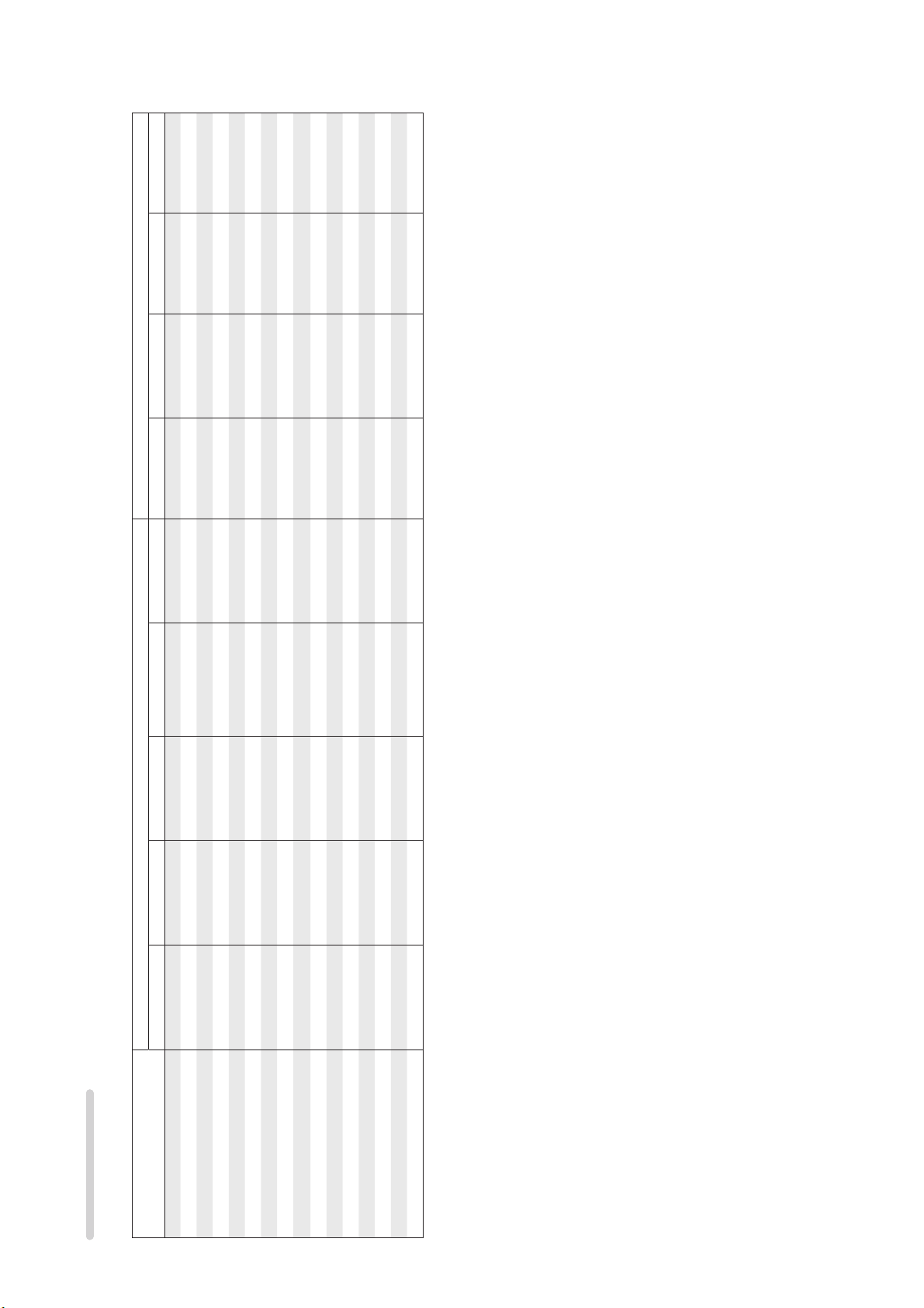
SURROUND MODES AND PARAMETERS
SS
D. Comp z3 DRCz4 LFE z5
z2
DSSS
z1
Channel output Surround Parameter
SS
z2
SDD D DSSS
SDD D D S S
SDD D D S S
SDD D D S
SDD D D S S
SDD D D S S
SDD D D S S
SDD D D S S
SDD D D S S
SDD D D S
S DSSS
SDD D
S D
Front L/R Center Surround L/R Surround Back L/R Subwoofer Mode
Surround mode
DTS NEO:6
DOLBY DIGITAL
DOLBY DIGITAL Plus
DOLBY TrueHD
DTS SURROUND
DTS 96/24
MULTI CH IN
DOLBY PRO LOGIC gx SDD D DSSS
STEREO
DIRECT (Multi-channel)
Symbols in the table
S This indicates the audio output channels or surround parameters that can be set.
D This indicates the audio output channels. The output channels depend on the settings of “Speaker Config.”.
DIRECT (2channel)
DOLBY PRO LOGIC g S D D DSSS
DTS-HD
S D
DTS Express
MULTI CH STEREO
VIRTUAL
z1 A signal for each channel contained in an input signal is output as audio.
z2 Only when “Mode” is set to “LFE+Main”, sound is output from the subwoofer.
z3 This item can be selected when a Dolby Digital or DTS signal is played.
z4 This item can be selected when a Dolby TrueHD signal is played.
z5 This item can be selected when a Dolby Digital or DTS signal or DVD-Audio is played.
28
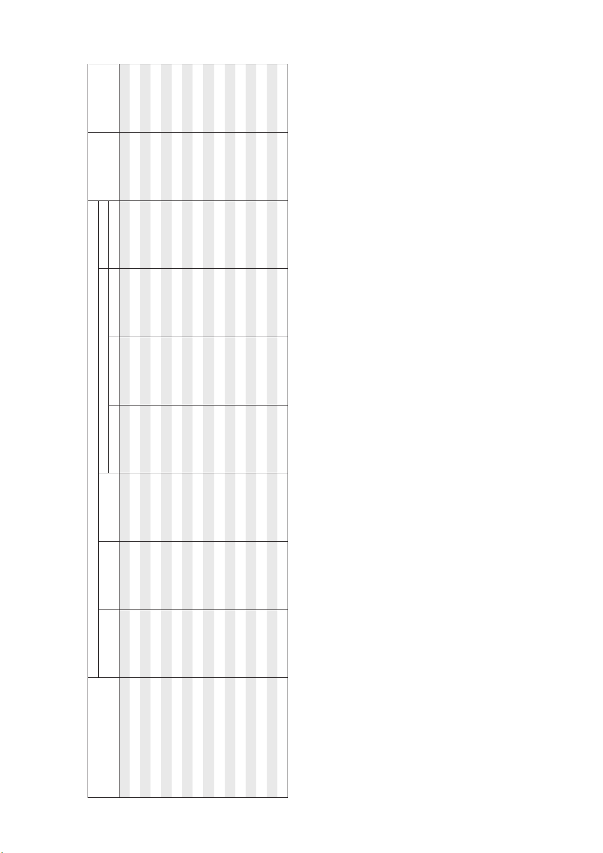
RESTORER z7
Tone
NEO:6 Music mode only
PRO LOGIC g/gx Music mode only
Panorama Dimension Center Width Center Image
Surround Parameter
SS
SS
z2
S
S.Back Subwoofer
AFDM z6
Surround mode
DIRECT (2 channel)
SS S
DIRECT (Multi-channel)
STEREO
MULTI CH IN
DOLBY PRO LOGIC gx S SSS SS
DOLBY PRO LOGIC g S SSS SS
S SSS
SS S
SS S
SS
SS S
SS S
DOLBY DIGITAL
DOLBY DIGITAL Plus
DOLBY TrueHD
DTS SURROUND
DTS NEO:6
DTS 96/24
S SS
SS
SS S
z2 Only when “Mode” is set to “LFE+Main”, sound is output from the subwoofer.
z6 This item can be selected when a Dolby Digital or DTS or DVD-Audio signal is played.
z7 This item can be set when the input signal is analog, PCM 48 kHz or 44.1 kHz.
DTS-HD
DTS Express
MULTI CH STEREO
VIRTUAL
29

DOLBY
DIGITAL
DOLBY
DIGITAL
(2ch)
(4/3ch)
DOLBY
DIGITAL
(5.1/5/4ch)
Flag)
DOLBY
(With no
DIGITAL EX
DOLBY
(With Flag)
DIGITAL EX
DOLBY
DIGITAL Plus
DOLBY
TrueHD
DTS 96/24
DTS
(5.1ch)
Input signal types and formats
MTRX
DTS ES
DSCRT
DTS ES
(With Flag)
(With Flag)
F
SSF
S S
DS
SFFF
F
DTS
EXPRESS
High
DTS-HD
Resolution
Audio
Master
DTS-HD
(2ch)
LINEAR PCM
PCM DTS-HD DTS DOLBY DOLBY DIGITAL
(multi ch)
LINEAR PCM
ANALOG
Audio
F
F
F
SS S
SS S
z F D
z F D
z SSS
z SSSS
SS S
z If “Speaker Config.“ – “S.B(Pre)“ is set to “None”, this surround mode cannot be selected.
Surround mode NOTE
DTS NEO:6 CINEMA
DTS NEO:6 MUSIC
DTS-HD MSTR
DTS-HD HI RES
DTS ES DSCRT6.1
DTS ES MTRX6.1
DTS SURROUND
DTS 96/24FDTS + PLgx CINEMA z SSSS
DTS + PLgx MUSIC z SSSS
DTS EXPRESS
DTS + NEO:6
Symbols in the table
F This indicates the default surround mode.
D This indicates the surround mode that is fixed when “AFDM” is set to “ON”.
S This indicates the selectable surround mode.
DTS SURROUND
DOLBY TrueHD
DOLBY SURROUND
30
DOLBY DIGITAL+
DOLBY DIGITAL EX
DOLBY DIGITAL
DOLBY (D) +PLgx CINEMA z F
DOLBY (D) +PLgx MUSIC z SSSS
DOLBY PRO LOGIC gx CINEMA zS S S
DOLBY PRO LOGIC gx MUSIC zS S S
DOLBY PRO LOGIC gx GAME zS S S
DOLBY PRO LOGIC g CINEMA SS S
DOLBY PRO LOGIC g MUSIC SS S
DOLBY PRO LOGIC g GAME SS S
DOLBY PRO LOGIC
Loading…
Denon AVR-1311
AV SURROUND RECEIVER
AVR-1312
Owner’s Manual
Basic version
Advanced version
Information
View the manual for the Denon AVR-1311 here, for free. This manual comes under the category receivers and has been rated by 9 people with an average of a 8.2.
This manual is available in the following languages: English. Do you have a question about the Denon AVR-1311 or do you need help?
Ask your question here
Index
- Getting started
- Basic version
- Advanced version
- Information
Product Images (2)

Denon AVR-1311 specifications
Below you will find the product specifications and the manual specifications of the Denon AVR-1311.
The Denon AVR-1311 is a receiver designed for home entertainment systems. With its sleek and modern design, it seamlessly blends into any home decor. The receiver delivers high-quality audio and video performance, allowing users to immerse themselves in their favorite movies, shows, and music.
Equipped with advanced technology, the Denon AVR-1311 offers a wide range of connectivity options. It comes with multiple HDMI inputs, enabling users to connect various devices such as gaming consoles, Blu-ray players, and set-top boxes. Additionally, it supports audio return channel functionality, allowing the TV’s audio to be transmitted back to the receiver through a single HDMI cable.
The Denon AVR-1311 boasts a powerful amplifier, delivering clear and dynamic sound. With its advanced surround sound processing technology, it creates an immersive audio experience, making users feel like they are part of the action.
The receiver also features a user-friendly interface, making it easy to navigate and control. With its intuitive menu system and clear on-screen displays, users can easily adjust settings to their preference. Furthermore, it includes a remote control, providing convenient access to all functions.
In terms of connectivity, the Denon AVR-1311 supports various audio formats, including Dolby TrueHD and DTS-HD Master Audio. It also has multiple audio outputs, allowing users to connect additional speakers for a more immersive surround sound experience.
Overall, the Denon AVR-1311 is a reliable and high-performing receiver, perfect for those seeking an exceptional audio and video experience in their home entertainment system.
General
| Brand | Denon |
| Model | AVR-1311 | AVR1311BKE2 |
| Product | receiver |
| Language | English |
| Filetype | User manual (PDF) |
Frequently Asked Questions
Can’t find the answer to your question in the manual? You may find the answer to your question in the FAQs about the Denon AVR-1311 below.
How do I connect my Denon AVR-1311 to my TV?
Use an HDMI cable to connect the HDMI OUT port on the receiver to the HDMI IN port on your TV. Make sure to select the correct input source on your TV and receiver.
How can I troubleshoot audio issues on my Denon AVR-1311?
Check the speaker connections and ensure they are securely plugged into the correct terminals. Also, verify that the speaker wires are not damaged. Finally, check the audio settings on the receiver and ensure the correct input and output settings are selected.
How do I adjust the sound settings on my Denon AVR-1311?
Press the «Sound Mode» button on the remote control to cycle through the available sound modes and choose the one that suits your preference. Additionally, you can adjust bass, treble, and other audio settings using the «Tone Control» options in the receiver’s on-screen menu.
What should I do if there is no video output from my Denon AVR-1311?
First, check the connection between the receiver and your TV. Ensure that the HDMI cable is securely connected and try using a different HDMI input on your TV. If the issue persists, try resetting the receiver by unplugging it from the power source for a few minutes, then plug it back in and power it on.
How can I set up the FM radio on my Denon AVR-1311?
Connect the supplied FM antenna to the FM ANTENNA socket on the back of the receiver. Extend and position the antenna for optimal reception. Press the «Tuner» button on the remote control, select FM mode, and use the arrow keys to tune into your desired radio station.
Can bluetooth devices of different brands be connected to each other?
Yes, bluetooth is a universal method that allows different devices equipped with bluetooth to connect to each other.
What is bluetooth?
Bluetooth is a way of exchanging data wirelessly between electronic devices via radio waves. The distance between the two devices that exchange data can in most cases be no more than ten metres.
What is HDMI?
HDMI stands for High-Definition Multimedia Interface. An HDMI cable is used to transport audio and video signals between devices.
When is my volume too loud?
A volume above 80 decibels can be harmful to hearing. When the volume exceeds 120 decibels, direct damage can even occur. The chance of hearing damage depends on the listening frequency and duration.
How can I best clean my receiver?
A slightly damp cleaning cloth or soft, dust-free cloth works best to remove fingerprints. Dust in hard-to-reach places is best removed with compressed air.
Wat is Dolby Atmos?
Dolby Atmos is a technology that ensures that the sound is reflected from the ceiling to where you are listening. This makes it possible to create a 5.1 effect with only 1 speaker.
Is the manual of the Denon AVR-1311 available in English?
Yes, the manual of the Denon AVR-1311 is available in English .
Is your question not listed? Ask your question here
-
Page 1: Denon AVR-1311
D&M Holdings Inc. SER VICE MANUAL e e Copyright 2010 D&M Holdings Inc. All rights reserved. W ARNING: Violators will be prosecuted to the maximum extent possible. MODEL JP E3 E3B E2 EK EA E1 E1C A VR-1311 33 A VR-391 33 A V SURROUND RECEIVER MODEL JP E3 E3B E2 EK EA E1 E1C DHT -1311XP 3 DHT -391XP 33 3 5.1CH HOME THEA TER SYSTEM Ve r . 3 ?[…]
-
Page 2: Denon AVR-1311
2 SAFETY PRECAUTIONS The following check should be performed for the continued protection of the customer and service technician. LEAKAGE CURRENT CHECK Before returning the unit to the customer , make sure you make either (1) a leakage current check or (2) a line to chassis resistance check. if the leakage current exceeds 0.5 milliamps, or if the r[…]
-
Page 3: Denon AVR-1311
3 NOTE FOR SCHEMA TIC DIAGRAM W ARNING: Parts marked with this symbol z have critical characteristics. Use ONL Y replacement parts recommended by the manufacture r. CAUTION: Before returning the unit to the customer , make sure you make either (1) a leakage current check or (2) a line to chassis resistance check. If the leakage current exceeds 0.5 […]
-
Page 4: Denon AVR-1311
4 TECHNICAL SPECIFICA TIONS n Audio Section • Power amplifi er Rated output : Front : 75 W + 75 W (8 Ω, 20 Hz – 20 kHz with 0.08 % T.H.D.) 110 W + 110 W (6 Ω, 1 kHz with 0.7 % T.H.D.) Center : 75 W (8 Ω, 20 Hz – 20 kHz with 0.08 % T.H.D.) 110 W (6 Ω, 1 kHz with 0.7 % T.H.D.) Surround : 75 W + 75 W (8 Ω, 20 Hz – 20 kHz with 0.08 % T.H.[…]
-
Page 5: Denon AVR-1311
5 245.0 43.5 30.0 30.5 20.0 20.7 22.2 86.0 340.0 166.5 146.5 43.5 381.4 338.5 248.0 435.0 DIMENSION The illustration is A VR-131 1 model.[…]
-
Page 6: Denon AVR-1311
6 CAUTION IN SER VICING Initializing A V SURROUND RECEIVER A V SURROUND RECEIVER initialization should be performed when the μ com, peripheral parts of μ com, and Digital P .W .B. are replaced. 1. T urn off the power using ON/ST ANDBY button. 2. Press ON/ST ANDBY button while simultaneously pressing SURROUND MODE 0 and SURROUND MODE 1 buttons. 3.[…]
-
Page 7: Denon AVR-1311
7 DISASSEMBL Y • Disassemble in order of the arrow of the fi gure of following fl ow . • In the case of the re-assembling, assemble it in order of the reverse of the following fl ow . • In the case of the re-assembling, observe «attention of assembling» it. • If wire bundles are untied or moved to perform adjustment or parts re[…]
-
Page 8: Denon AVR-1311
8 1. FRONT P ANEL ASSY (1) Remove the screws. (2) Cut the wire clamp band, then disconnect the connector wires and FFC cable. Remove the screws. (3) Remove the screws. TOP COVER FRONT PANEL ASSY → Proceeding : View from bottom CN209 CN71 FFC cable CN44 cut cut FRONT P ANEL ASSY WIRE SUPPORT UNIT Please refer to «EXPLODED VIEW» for t[…]
-
Page 9: Denon AVR-1311
9 2. HDMI UNIT (1) Remove the screws. (2) Disconnect the connector wire and FFC cable. TOP COVER HDMI UNIT → Proceeding : Direction of photograph: A CN12 FFC cable HDMI UNIT[…]
-
Page 10: Denon AVR-1311
10 3. INPUT UNIT (1) Remove the screws. (2) Disconnect the connector wires and FFC cables, then remove the screws. TOP COVER HDMI UNIT → INPUT UNIT → Proceeding : Direction of photograph: A CN42 CN71 CN43 FFC cable FFC cable INPUT UNIT[…]
-
Page 11: Denon AVR-1311
11 4. RADIA TOR ASSY (1) Remove the screws. (2) Disconnect the connector wires, then remove the screws. TOP COVER HDMI UNIT → INPUT UNIT → RADIATOR ASSY → Proceeding : Direction of photograph: A RADIA TOR ASSY CN71 CN44 CN45 CN41 CN47 CN48 CN46[…]
-
Page 12: Denon AVR-1311
12 (3) Remove the RADIA TOR ASSY from the main unit. 5. POWER UNIT 6. POWER TRANS Direction of photograph: C Please refer to «EXPLODED VIEW» for the disassembly method of each P .W .B included in RADIA TOR ASSY . TOP COVER POWER UNIT → Proceeding : Please refer to «EXPLODED VIEW» for the disassembly method of POWER UNIT . […]
-
Page 13: Denon AVR-1311
13 SPECIAL MODE Special mode setting button b Press the ON/ST ANDBY button to turn on while pressing both buttons A and B at the same time. Mode Button A Button B Contents μ com/DSP V ersion display mode ST A TUS DIMMER Firmware versions such as Main, DSP are displayed in the FL display . Errors are displayed when they occur . (Refer to page 14.) […]
-
Page 14: Denon AVR-1311
14 1. μ com/DSP V ersion display mode 1.1. Operation speci fi cations μ com/DSP version display mode: When started up, the version information is displayed. Starting up: With the «DIMMER» and «ST A TUS» buttons pressed, press the «ON/ST ANDBY» button to turn the power on. Now , press the «ST A TUS» button […]
-
Page 15: Denon AVR-1311
15 ABOUT REPLACE THE MICROPROCESSOR WITH A NEW ONE When replaced of the U-PRO (Microprocessor) or the Flash ROM, conrm contents of the following. PWB Name Ref . No. Desc ript ion Afte r repl aced R emark DIGIT AL IC91 T5CN5 B SOFTW ARE: Main DIGIT AL IC82 ST25VF080B-50-4C-S2AF B SOFTW ARE: DSP ROM After replaced A : Mask ROM (With software). No […]
-
Page 16: Denon AVR-1311
16 2. UPDA TE FIRMW ARE (1) Connect the update terminal of A V receiver with the “Writing Kit”. (2) Set the switch of “Writing Kit» (Refer to the table below). DSPBOOT CE EPM CNVSS HHHH (3) Press the «ON/ST ANDBY» button to turn the power on of A V receiver . (4) Set the switch of “Writing Kit» (Refer to the table below)[…]
-
Page 17: Denon AVR-1311
17 DSP SF1 (8) Choose Ram File(OnBoard_M330.s32). Choose Ram File(OnBoard_M330.s32).[…]
-
Page 18: Denon AVR-1311
18 (9) Choose Flash File(DSP : SF1). Choose «AVR1311_SF1_*_*_*_01.s32». Choose «Hex File (*.S32)».[…]
-
Page 19: Denon AVR-1311
19 (10) Click the “Start” button. The Setup Status bar appears.[…]
-
Page 20: Denon AVR-1311
20 (1 1) «Finished!!» is displayed. Click the «OK»” button. (12) Set the switch of “Writing Kit» (Refer to the table below). DSPBOOT CE EPM CNVSS HHHH (13) Press the «RESET» switch of “Writing Kit». (14) A V receiver is power on and starts update of DSP1. (15) «Write Comleted» is displayed in […]
-
Page 21: Denon AVR-1311
21 (19) Choose Flash File(DSP : SF2). Choose «AVR1311_SF2_*_*_*_01.s32». Choose «Hex File (*.S32)».[…]
-
Page 22: Denon AVR-1311
22 (20) Click the “Start” button. (21) «Finished!!» is displayed. Click the «OK»” button. The Setup Status bar appears.[…]
-
Page 23: Denon AVR-1311
23 (22) Set the switch of “Writing Kit» (Refer to the table below). DSPBOOT CE EPM CNVSS HHHH (23) Press the «RESET» switch of “Writing Kit». (24) A V receiver is power on and starts update of DSP2. (25) «Write Comleted» is displayed in the FL tube. (26) Set the switch of “Writing Kit» (Refer to the table be[…]
-
Page 24: Denon AVR-1311
24 (29) Choose Flash File(MAIN). Choose «AVR1311.s32». Choose «Hex File (*.S32)».[…]
-
Page 25: Denon AVR-1311
25 (30) Click the “Start” button. (31) «Finished!!» is displayed. Click the «OK»” button. The Setup Status bar appears.[…]
-
Page 26: Denon AVR-1311
26 (32) Set the switch of “Writing Kit» (Refer to the table below). DSPBOOT CE EPM CNVSS HHHH (33) Press the «RESET» switch of “Writing Kit». (34) Initializing. 1. T urn off the power using ON/ST ANDBY button. 2. Press ON/ST ANDBY button while simultaneously pressing SURROUND MODE 0 and SURROUND MODE 1 buttons. 3. Check that[…]
-
Page 27: Denon AVR-1311
27 ADJUSTMENT Audio Section Idling Current Required measurement equipment: DC V oltmeter 1. Preparation (1) Avoid direct blow from an air conditioner or an electric fan, and adjust the unit at normal room temperature 15 °C ~ 30 °C. (2) Presetting • POWER (Power source switch) OFF • SPEAKER (Speaker terminal) No load (Do not connect speaker , […]
-
Page 28: Denon AVR-1311
28 SURROUND MODES AND P ARAMETERS Symbols in the table S This indicates the audio output channels or surround parameters that can be set. D This indicates the audio output channels. The output channels depend on the settings of “Speaker Config.”. Surround mode Channel output Surround Parameter Front L/R Center Surround L/R Surround Back L/R Su[…]
-
Page 29: Denon AVR-1311
29 Surround mode Surround Parameter Tone RESTORER z 7 AFDM z 6 S.Back Subwoofer PRO LOGIC g / g x Music mode only NEO:6 Music mode only Panorama Dimension Center Width Center Image DIRECT (2 channel) S z 2 DIRECT (Multi-channel) STEREO SS MULTI CH IN SS S DOLBY PRO LOGIC g x S SSS SS DOLBY PRO LOGIC g S SSS SS DTS NEO:6 S SSS DOLBY DIGITAL SS S DOL[…]
-
Page 30: Denon AVR-1311
30 Symbols in the table F This indicates the default surround mode. D This indicates the surround mode that is fixed when “AFDM” is set to “ON”. S This indicates the selectable surround mode. Surround mode NOTE Input signal types and formats ANALOG PCM DTS-HD DTS DOLBY DOLBY DIGITAL LINEAR PCM (multi ch) LINEAR PCM (2ch) DTS-HD Master Audi[…]
-
Page 31: Denon AVR-1311
31 Surround mode NOTE Input signal types and formats ANALOG PCM DTS-HD DTS DOLBY DOLBY DIGITAL LINEAR PCM (multi ch) LINEAR PCM (2ch) DTS-HD Master Audio DTS-HD High Resolution Audio DTS EXPRESS DTS ES DSCRT (With Flag) DTS ES MTRX (With Flag) DTS (5.1ch) DTS 96/24 DOLBY TrueHD DOLBY DIGITAL Plus DOLBY DIGITAL EX (With Flag) DOLBY DIGITAL EX (With […]
-
Page 32: Denon AVR-1311
32 YES YES YES YES NO NO NO Is the ON/ST ANDBY indicator on the front panel fl ashing red? Does the power turn on when the POWER switch is turned off then back on? Check the primary ciruitry parts including the POWER switch(for poor contacts, etc.), and replace any defective parts. Check the microprocessor periphery circuitry and replace any degec[…]
-
Page 33: Denon AVR-1311
33 A VR-131 1 model only 2. Analog video OK OK OK OK MONITOR OUT(CVBS) Output NG MONITOR OUT(COMPONENT) Output NG Check ±5V +5V : C755 -5V : C754 Check ±5V +5V : C797 -5V : C799 Check output Output V : IC71-1pin Check output Output Y : C785 Output Pb : C787 Output Pr : C789 Check cable between main unit and monitor or Check monitor . Check cable […]
-
Page 34: Denon AVR-1311
34 YES YES YES YES NO NO NO NO NO YES YES YES No picture or sound is output. Check BD/DVD player . Check HDMI/DVI cable connection. (1) Is the HDMI/DVI cable properly connected? (3) Are you using a certi fi ed HDMI cable (one with the HDMI stamp)? (3) Are you using an HDMI/DVI cable less than 5 meters in length? (4) Are the picture and sound outpu[…]
-
Page 35: Denon AVR-1311
35 YES YES YES Check TV (10) Is the TV HDCP-compatible? (14) Is the set’s input set to HDMI? (12) Is the TV’s input set to HDMI? (13) Are the picture and sound output when a different TV is used? Check set (A VR-131 1, 391) (1 1) Is the TV compatible with resolutions of 1080P? Use an HDCP-compatible TV . PC TVs cannot be used. Check set&a[…]
-
Page 36: Denon AVR-1311
36 YES YES YES (19) Check xtal oscillator . Is there 28.6363MHz oscillation of X101? (20) Check RESET . Is RESET waveform con fi rmed in IC1 1 (97pin), when power is turned on? (If continued to «H» or » L», proceed to «NO».) HDMI output circuitry is defective (IC1 1 and surrounding circuitry). (21) Check control signa[…]
-
Page 37: Denon AVR-1311
37 3.2. HDMI test point and waveforms A B C D +5V TMDS D2+ HPD TMDS D0- TMDS D0+ TMDS D1+ TMDS D1+ TMDS D1- TMDS D1- TMDS D2- 43pin 㧦 DDC_DA T A 44pin 㧦 DDC_CLK DDC_DA T A DDC_CLK TMDS D2+ TMDS D0+ HPD TMDS D1+ +5V TMDS CK+ TMDS D1- TMDS CK- TMDS D2- TMDS D0- HDMI_SCL HDMI_SDA Detail A Detail C Detail D Detail B[…]
-
Page 38: Denon AVR-1311
38 DDC_CLK/DDC_DA T A/TMDS : Check item (15),(17) IPINDE/IPINVSYNC/IPINHSYNC/IPINPCK : Check item (21) 0.9V 2.48V TMDS SIGNAL DDC_CLK DDC_DATA HDMI_SDA HDMI_SCL[…]
-
Page 39: Denon AVR-1311
CLOCK FLOW & W A VE FORM IN DIGIT AL BLOCK 䇭 㩿㪏㪎㪀㪘㪧㪇㪶㪦㪬㪫 㩿㪏㪏㪀㪘㪧㪈㪶㪦㪬㪫 㩿㪏㪐㪀㪘㪧㪉㪶㪦㪬㪫 㩿㪐㪇㪀㪘㪧㪊㪶㪦㪬㪫 㩿㪐㪈㪀㪘㪧㪋㪶㪦㪬㪫 㩿㪐㪋㪀㪘㪧㪌㪶㪦㪬㪫 㩿㪐㪌㪀㪪㪚㪣㪢㪶㪦㪬㪫 㩿㪐㪍㪀㪤㪚㪣㪢㪶㪦㪬㪫 㪛㪘㪠㪈㪶㪛㪘[…]
-
Page 40: Denon AVR-1311
40 BLOCK DIAGRAM[…]
-
Page 41: Denon AVR-1311
41[…]
-
Page 42: Denon AVR-1311
42[…]
-
Page 43: Denon AVR-1311
43[…]
-
Page 44: Denon AVR-1311
44 LAEVEL DIAGRAM[…]
-
Page 45: Denon AVR-1311
45[…]
-
Page 46: Denon AVR-1311
46 18 17 16 15 14 13 12 11 10 9 8 7 6 5 4 3 2 1 G F E D C B A PRINTED WIRING BOARDS FRONT (COMPONENT SIDE) d PHONE (COMPONENT SIDE) d HEADPHONE (COMPONENT SIDE) d REGULA TOT (COMPONENT SIDE) d 鉛フリー半田 半田付けには、鉛フリー半田 (Sn-Ag-Cu) を使用してください。 Lead-free Solder When soldering, use the Lead-free Solde[…]
-
Page 47: Denon AVR-1311
47 1 2 3 4 5 6 7 8 9 10 11 12 13 14 15 16 17 18 G F E D C B A FRONT (FOIL SIDE) d PHONE (FOIL SIDE) d HEADPHONE (FOIL SIDE) d REGULA TOT (FOIL SIDE) d 1 2 3 D C B A 1 2 3 4 5 C B A 1 2 3 4 5 6 7 D C B A 鉛フリー半田 半田付けには、鉛フリー半田 (Sn-Ag-Cu) を使用してください。 Lead-free Solder When soldering, use the Lead-[…]
-
Page 48: Denon AVR-1311
48 鉛フリー半田 半田付けには、鉛フリー半田 (Sn-Ag-Cu) を使用してください。 Lead-free Solder When soldering, use the Lead-free Solder (Sn-Ag-Cu). POWER (COMPONENT SIDE) d POWER (FOIL SIDE) d VOLUME (COMPONENT SIDE) d VOLUME (FOIL SIDE) d AUX (COMPONENT SIDE) d AUX (FOIL SIDE) d 3 2 1 D C B A 4 3 2 1 D C B A 1 2 3 4 D C B[…]
-
Page 49: Denon AVR-1311
49 MAIN (COMPONENT SIDE) d Bar code 17 16 15 14 13 12 11 10 9 8 7 6 5 4 3 2 1 M L K J I H G F E D C B A 鉛フリー半田 半田付けには、 鉛フリー 半田 (Sn-Ag-Cu) を使用 してください。 Lead-free Solder When soldering, use the Lead-free Solder (Sn-Ag-Cu).[…]
-
Page 50: Denon AVR-1311
50 INPUT (COMPONENT SIDE) d 17 16 15 14 13 12 11 10 9 8 7 6 5 4 3 2 1 M L K J I H G F E D C B A 鉛フリー半田 半田付けには、 鉛フリー半田 (Sn-Ag-Cu) を使 用してください。 Lead-free Solder When soldering, use the Lead- free Solder (Sn-Ag-Cu).[…]
-
Page 51: Denon AVR-1311
51 INPUT (FOIL SIDE) d 1 2 3 4 5 6 7 8 9 10 11 12 13 14 15 16 17 M L K J I H G F E D C B A 鉛フリー半田 半田付けには、 鉛フリー半田 (Sn-Ag-Cu) を使 用してください。 Lead-free Solder When soldering, use the Lead- free Solder (Sn-Ag-Cu).[…]
-
Page 52: Denon AVR-1311
52 鉛フリー半田 半田付けには、鉛フリー半田 (Sn-Ag-Cu) を使用してください。 Lead-free Solder When soldering, use the Lead-free Solder (Sn-Ag-Cu). 13 12 11 10 9 8 7 6 5 4 3 2 1 G F E D C B A HDMI (COMPONENT SIDE)[…]
-
Page 53: Denon AVR-1311
53 鉛フリー半田 半田付けには、鉛フリー半田 (Sn-Ag-Cu) を使用してください。 Lead-free Solder When soldering, use the Lead-free Solder (Sn-Ag-Cu). HDMI (FOIL SIDE) 1 2 3 4 5 6 7 8 9 10 11 12 13 G F E D C B A[…]
-
Page 54: Denon AVR-1311
54 8 7 6 5 4 3 2 1 A B C D E F SCHEMA TIC DIAGRAMS (1/7) d[…]
-
Page 55: Denon AVR-1311
55 HDMI/TMDS SIGNAL LINE D2+ D2 SHIEL D D2- D1+ D2 SHIEL D D1- D1 SHIEL D D0+ D0- CK+ D1 SHIEL D CK- CE RE MOTE NC DDC CLK DDC DA T A GND +5V HP DET INPUT-4 D2+ D2 SHIEL D D2- D1+ D2 SHIEL D D1- D1 SHIEL D D0+ D0- CK+ D1 SHIEL D CK- CE RE MOTE NC DDC CLK DDC DA T A GND +5V HP DET INPUT-3 D2+ D2 SHIEL D D2- D1+ D2 SHIEL D D1- D1 SHIEL D D0+ D0- CK+ […]
-
Page 56: Denon AVR-1311
56 ANALOG AUDIO SIGNAL LINE 8 7 6 5 4 3 2 1 A B C D E F SCHEMA TIC DIAGRAMS (3/7) d[…]
-
Page 57: Denon AVR-1311
57 VIDEO SIGINAL LINE COMPONENT (Y) SIGNAL LINE 8 7 6 5 4 3 2 1 A B C D E F SCHEMA TIC DIAGRAMS (4/7) d[…]
-
Page 58: Denon AVR-1311
58 ANALOG AUDIO SIGNAL LINE DIGIT AL AUDIO SIGINAL LINE 8 7 6 5 4 3 2 1 A B C D E F SCHEMA TIC DIAGRAMS (5/7) d[…]
-
Page 59: Denon AVR-1311
59 8 7 6 5 4 3 2 1 A B C D E F SCHEMA TIC DIAGRAMS (6/7) d[…]
-
Page 60: Denon AVR-1311
60 ANALOG AUDIO SIGNAL LINE 8 7 6 5 4 3 2 1 A B C D E F SCHEMA TIC DIAGRAMS (7/7) d[…]
-
Page 61: Denon AVR-1311
WIRING DIA GRAM 61[…]
-
Page 62: Denon AVR-1311
EXPLODED VIEW C8 C9 C10 C1 C2 C3 C1 1 C12 C4 C5 C6 C7 C13 C14 C16 S1 1 X5 S6 X6 S12 X3 S4 S4 S4 X17 S4 S2 S2 S7 S5 X17 S7 X2 X10 S1 X17 S8 X4 S8 X3 S8 S8 A VR131 1 A VR131 1 A VR391 A VR391 X3 S9 S8 X2 S3 S3 S3 S8 X2 S3 X4 S5 X2 S3 S10 X4 X2 X2 X2 X2 X2 X2 X2 X2 S3 X4 S3 S3 C15 S7 S5 X17 S7 X2 X10 P1 P9 P2 P3 P4 P6 P10 P1 1 P4 P6 P5 P8 P7 P7 P8 P13[…]
-
Page 63: Denon AVR-1311
63 P AR TS LIST OF EXPLODED VIEW z Parts for which «nsp» is indicated on this table cannot be supplied. z P .W .B. ASS’Y for which «nsp» is indicated on this table cannot be supplied. When repairing the P .W .B. ASS’Y , check the board parts table and order replacement parts. z Part indicated with the mark » ★ &[…]
-
Page 64: Denon AVR-1311
64 Ref.No. Part No. Part Name Remarks Q’ty New P13 nsp PCB HOLDER CHE170 2 M1 nsp TOP BRACKET CMD1A355 2 M2 nsp BOTTOM CHASSIS CUA4A302 1 M3 nsp PCB BRACKET CMD1A417 2 M4 nsp PCB BRACKET CMD1A774 2 M5 nsp REAR P ANEL 131 1SPE2,131 1BKE2 CKF4A437Z 1 * M5 nsp REAR P ANEL 131 1SPE1C CKF3A437Y 1 * M5 nsp REAR P ANEL 391BKE3 CKF1A437Z 1 * M5 nsp RE[…]
-
Page 65: Denon AVR-1311
65 Ref.No. Part No. Part Name Remarks Q’ty New S9 nsp SCREW CTW3+12JR 2 S10 nsp SPECIAL SCREW CHD1A023R 4 S1 1 nsp SCREW BK CTB3+8JFZR 5 S1 1 nsp SCREW SP CTB3+8JFN 5 S12 nsp SCREW BK CTBD3+8JFZR 3 S12 nsp SCREW SP CTBD3+8JFN 3[…]
-
Page 66: Denon AVR-1311
66 P ACKING VIEW (for A VR-131 1, 391) P ARTS LIST OF P ACKING & ACCESSORIES (for A VR-131 1, 391) z Parts for which «nsp» is indicated on this table cannot be supplied. z Part indicated with the mark » ★ » is not illustrated in the exploded view . z The parts listed below are for maintenance only , might differ from the p[…]
-
Page 67: Denon AVR-1311
67 Ref.No. Part No. Part Name Remarks Q’ty New 8 00D94301 13403 FM 1 POLE ANT . 131 1SPE2,131 1BKE2, 131 1SPE1C,391BKEA CSA1A018Z 1 8 90M-ZA000230R FM 1 POLANT(UL) 391BKE3 CSA1A019Z 1 9 9431 16009500S AM LOOP ANT CSA1A032Z 1 10 nsp POL Y BAG CPB1061W 1 1 1 943531009950D OUTCAR TON BOX 131 1SPE2,131 1BKE2 CPG1A924X 1 * 1 1 943531009960D OUTCAR […]
-
Page 68: Denon AVR-1311
68 P ACKING VIEW (for DHT -131 1XP , 391XP) P ARTS LIST OF P ACKING & ACCESSORIES (for DHT -131 1XP , 391XP) z Parts for which «nsp» is indicated on this table cannot be supplied. z Part indicated with the mark » ★ » is not illustrated in the exploded view . z The parts listed below are for maintenance only , might differ […]
-
Page 69: Denon AVR-1311
69 Ref.No. Part No. Part Name Remarks Q’ty New 4 943533009940D SNOW P AD(R) CPS1A883 1 * 5-1 541 1 10486002D INSTRUCTION MANUAL A 131 1SPE2,131 1BKE2 CQX1A1538Z 1 * 5-2 541 1 10603005D INSTRUCTION MANUAL B 131 1SPE2,131 1BKE2 CQX1A1538Y 1 * 5-1 541 1 10484006D INSTRUCTION MANUAL 391BKE3,391BKE3B CQX1A1537Z 1 * 5-1 541 1 10489001D INSTRUCTION M[…]
-
Page 70: Denon AVR-1311
70 SEMICONDUCT ORS Only major semiconductors are shown, general semiconductors etc. are omitted to list. The semiconductor which described a detailed drawing in a schematic diagram are omitted to list. 1. IC’s R2A15218FP (INPUT :IC61) PRELIMINARY AGND SWC AGND SLC AGND SBLC INLB/RECL2 INRB/RECR2 INR11/RECR5 INL10/RECL4 RECR3 INL11/RECL5 FLIN1 […]
-
Page 71: Denon AVR-1311
71 R2A15218FP T erminal Functions PRELIMINARY PIN No. Name Function 49 DATA Input pin of control data 50 CLOCK Input pin of control clock Output pin of FL/FR /C/SW/SL/SR /SBL/SBR channel FRIN2, FLIN2, SRN2,SLIN2, SWIN2,CIN2, SBRIN2,SBLIN2 43,42, 41,40, 39,38, 37,36 Input pin of L/R/C/SW/ SL/SR/SBL/S BR channel (Multi IN 1/2) Output pin for L/R chan[…]
-
Page 72: Denon AVR-1311
72 NJM2595M (INPUT : IC71) NJM2586M (INPUT : IC73) 13 9 7 5 3 20k 20k 20k 20k 16 10 14 2 1 15 11 8 12 6 4 6dB Amp 75 Ω Dri v er S3 S2 S4 S1 20k 20k 20k S5 S6 S7 Vin1 Vin2 Vin3 Vin4 Vin5 SW 3 SW 4 SW 5 SW 1 SW 2 V + GND V — Vout3 Vout2 Vout1 6dB Amp 6dB Amp 75 Ω Dri v er 75 Ω Dri v er 9 10 8 5 6 7 4 3 2 1 11 12 13 16 15 14 17 18 19 20 21 22 23 24[…]
-
Page 73: Denon AVR-1311
73 CS42528 (INPUT : IC84) CS42528 Block diagram[…]
-
Page 74: Denon AVR-1311
74 CS42528 T erminal Functions[…]
-
Page 75: Denon AVR-1311
75 CS497024CVZ (INPUT : IC81)[…]
-
Page 76: Denon AVR-1311
76 CS497024CVZ Block diagram M12L16161A5TG (INPUT : IC83)[…]
-
Page 77: Denon AVR-1311
77 TC74VHC157FT (INPUT : IC85) T5CN5 (INPUT : IC91) 4A V CC 16 4B 15 14 13 12 11 10 1 2 3 4 5 6 7 1Y 2A 2B 2Y GND 4Y 8 3Y 9 3A 3B 1A 1B SELECT ST A S G B A Y B A Y B A Y B Y[…]
-
Page 78: Denon AVR-1311
78 T5CN5 T erminal Functions[…]
-
Page 79: Denon AVR-1311
79 ADV7622BSTZ (HDMI : IC1 1) DDCC_SDA 5V_DETC HP_CTRLC RXB_2+ RXB_2- TVDD RXB_1+ RXB_1- CGND RXB_0+ RXB_0- TVDD RXB_C+ RXB_C- CGND CVDD DDCB_S CL DDCB_S DA DVDD DGND 5V_DETB HP_CTRLB RXA_2+ RXA_2- TVDD RXA_1+ RXA_1- CGND RXA_0+ RXA_0- TVDD RXA_C+ RXA_C- CGND CVDD DDCA_S CL 144 143 142 141 140 139 138 137 136 135 134 133 132 131 130 129 128 127 126[…]
-
Page 80: Denon AVR-1311
80 ADV7622BSTZ T erminal Functions Location Mnemonic Type Description 1 DDCC_SCL Digital Input HDCP slave serial clock port C. DDCC_SCL is a 3.3 V input that is 5 V tolerant. 2 CVDD Power Receiver comparator supply voltage (1.8V) 3 CGND Ground TVDD and CVDD Ground 4 RXC_C- HDMI Input Digital input clock Com plement of port C in the HDMI interface. […]
-
Page 81: Denon AVR-1311
81 Location Mnemonic Type Description D in the HDMI interface. 27 RXD_0+ HDMI Input Digital input channel 0 True of port D in the HDMI interface. 28 CGND Ground TVDD and CVDD Ground 29 RXD_1- HDMI Input Digital input channel 1 complement of port D in the HDMI interface. 30 RXD_1+ HDMI Input Digital input channel 1 true of port D in the HDMI interfa[…]
-
Page 82: Denon AVR-1311
82 Location Mnemonic Type Description 49 TXGND Ground TXAVDD Ground 50 TX0- HDMI Output Differential Output Channel 0 Complement. Differential output of the red data at 10× the pixel clock rate; supports TMDS logic level. 51 TX0+ HDMI Output Differential Output Channel 0 True. Differential output of the red data at 10× the pixel clock rate; suppo[…]
-
Page 83: Denon AVR-1311
83 Location Mnemonic Type Description N = 1, 2, 3, or 4. Set to 128 × sampling frequency (fs), 256 × fs, 384 × fs, or 512 × fs. Supports 1.8 V to 3.3 V CMOS logic levels. 69 SCLK_IN Digital Input I2S Audio Clock. Supports CMOS logic levels from 1.8 V to 3.3 V. 70 AP5_IN Digital Input Audio Input Port 5. CMOS logic levels from 1.8 V to 3.3 V. 71[…]
-
Page 84: Denon AVR-1311
84 Location Mnemonic Type Description 87 AP0_OUT Digital Output Audio output port 0. 88 AP1_OUT Digital Output Audio output port 1. 89 AP2_OUT Digital Output Audio output port 2. 90 AP3_OUT Digital Output Audio output port 3. 91 AP4_OUT Digital Output Audio output port 4. 92 DGND Ground Ground for DVDD 93 DVDD Power Digital supply voltage (1.8 V) 9[…]
-
Page 85: Denon AVR-1311
85 Location Mnemonic Type Description 112 RXA_C- HDMI Input Digital input clock Complement of port A in the HDMI interface. 113 RXA_C+ HDMI Input Digital input clock True of port A in the HDMI interface. 114 TVDD Power Receiver terminator supply voltage (3.3 V) 115 RXA_0- HDMI Input Digital input channel 0 complement of port A in the HDMI interface[…]
-
Page 86: Denon AVR-1311
86 EX3A V (HDMI : IC16) EX3A V T erminal Functions Location Mnemonic Type Description 138 RXB_1+ HDMI Input Digital input channel 1 true of port B in the HDMI interface. 139 TVDD Power Receiver terminator supply voltage (3.3 V) 140 RXB_2- HDMI Input Digital input channel 2 complement of port B in the HDMI interface. 141 RXB_2+ HDMI Input Digital in[…]
-
Page 87: Denon AVR-1311
87 2. FL DISPLA Y FLD (18-ST -13GINK) (FRONT : U100) PIN CONNECTION GRID ASSIGNMENT 59 1[…]
-
Page 88: Denon AVR-1311
88 ANODE CONNECTION[…]
-
Page 89: Denon AVR-1311
89 P ARTS LIST OF P .W .B. UNIT z Parts for which «nsp» is indicated on this table cannot be supplied. z Part indicated with the mark » ★ » is not illustrated in the exploded view . z The parts listed below are for maintenance only , might differ from the parts used in the unit in appearances or dimensions. Note: The symbols i[…]
-
Page 90: Denon AVR-1311
90 Ref. No. Part No. Part Name Remarks Q’ty New C21 1 nsp CHIP CAP 0.1UF 50V K CCUS1H104KC C213 nsp MYLAR CAP 0.1UF 50V J HCQI1H104JZT C214,215 943134010520S ELECT CAP 10UF 50V CCEA1HH100T C216 943134010530S ELECT CAP 1UF 50V CCEA1HH1R0T C217 943134010670S ELECT CAP 47UF 16V CCEA1CKS470T C218,219 943134010520S ELECT CAP 10UF 50V CCEA1HH100T C2[…]
-
Page 91: Denon AVR-1311
91 Ref. No. Part No. Part Name Remarks Q’ty New CN207 nsp LOCKINGTYPE STRAIGHTW AFER 2mm CJP05GI236ZW CN208 nsp W AFER STRAIGHT CJP05GA19ZY CN209 nsp W AFER ANGLE(2.5mm) CJP05GB03ZY z F201 943652000620S FUSE(0.1A 372SERIES/TR5) CBA2D0100A3EYT FL201 9431720101 10S VFD HCA-18SM01T CFLHCA18SM01T * GND21,22 nsp PCB BRACKET CMD1A569 JK201 90M-YT004[…]
-
Page 92: Denon AVR-1311
92 MAIN P .W .B. UNIT ASS’Y Ref. No. Part No. Part Name Remarks Q’ty New SEMICONDUCTORS GROUP IC41 00D2630641002 REGULA TOR IC NJM7912F A HVINJM7912F A IC42 00D2630801004 REGULA TOR IC NJM7812F A HVINJM7812F A IC45 00D2631 162014 REGULA TOR IC KIA78R05PI HVIKIA78R05PI IC46 231010031706S REGULA TOR IC KIA278R05PI HVIKIA278R05PI Q401 00MHT8[…]
-
Page 93: Denon AVR-1311
93 Ref. No. Part No. Part Name Remarks Q’ty New ZD41 943202010070S DIODE ZJ12B CVDZJ12BT ZD48 943202010080S DIODE ZJ5.1B CVDZJ5.1BT ZD49 90M-HD302440R DIODE ZJ4.7B CVDZJ4.7BT ZD51-60 90M-HD302390R DIODE ZJ3.3B CVDZJ3.3BT RESISTORS GROUP R494-501 nsp MET AL OXIDE FILM RES(4.7KOHM 5% 1W) KRG1SANJ4R7RT R502 nsp MET AL OXID EFILM RES(120OHM 1W J) […]
-
Page 94: Denon AVR-1311
94 Ref. No. Part No. Part Name Remarks Q’ty New C423-426 nsp CERAMIC CAP 33PF 50V J CCCT1H330JC C427 943134010660S ELECT CAP 470UF 6.3V CCEA0JH471T C428 943134010490S ELECT CAP 100UF 10V CCEA1AH101T C429-431 nsp MYLAR CAP 0.01UF 100V J 131 1E2 HCQI1H103JZT C429-431 nsp MYLAR CAP 1000PF 100V J MYLAR 131 1E1C,391E3, 391E3B,391EA HCQI1H102JZT C43[…]
-
Page 95: Denon AVR-1311
95 Ref. No. Part No. Part Name Remarks Q’ty New C504 943134010600S ELECT CAP 3300UF 16V CCEA1CH332E C505 943134010680S ELECT CAP 47UF 50V CCEA1HH470T C508 943134010520S ELECT CAP 10UF 50V CCEA1HH100T C559 943134010470S ELECT CAP 0.1UF 50V CCEA1HH0R1T C561 943134010530S ELECT CAP 1UF 50V CCEA1HH1R0T C563,564 943134010470S ELECT CAP 0.1UF 50V CC[…]
-
Page 96: Denon AVR-1311
96 INPUT P .W .B. UNIT ASS’Y Ref. No. Part No. Part Name Remarks Q’ty New SEMICONDUCTORS GROUP IC60 943231010390S REGULA TOR IC KIA7805BPI CVIKIA7805BPI * IC61 943235003810S IC R2A15218FP CVIR2A15218FP IC62-65 00D2631289900 IC AZ4580MTR-E1 CVIAZ4580MTR-E1 IC66,67 00D2630934900 IC BA4510F HVIBA4510F IC68 943231010390S REGULA TOR IC KIA7805[…]
-
Page 97: Denon AVR-1311
97 Ref. No. Part No. Part Name Remarks Q’ty New RN61 nsp CHIP RES(100OHM 5% 1608X4) CRJ104DJ101T RN80 nsp CHIP RES(33OHM 5%,1608X4) CRJ104DJ330T RN81,82 nsp CHIP RES(10KOHM 5% 1608X4) CRJ104DJ103T RN83-90 nsp CHIP RES(33OHM 5% 1608X4) CRJ104DJ330T RN91,92 nsp CHIP RES(100OHM 5% 1608X4) CRJ104DJ101T RN93 nsp CHIP RES(10KOHM 5% 1608X4) CRJ104DJ1[…]
-
Page 98: Denon AVR-1311
98 Ref. No. Part No. Part Name Remarks Q’ty New C696,697 943134010610S ELECT CAP 4.7UF 50V CCEA1HH4R7T C698 nsp CHIP CAP 0.1UF 50V CCUS1H104KC C701-704 nsp CHIP CAP 1500PF 50VK CCUS1H152KC C705,706 nsp CHIP CAP 330PF 50V J CCUS1H331JA C707,708 nsp CHIP CAP 1500PF 50VK CCUS1H152KC C709 nsp CHIP CAP 0.1UF 50V CCUS1H104KC C710,71 1 nsp CHIP CAP 3[…]
-
Page 99: Denon AVR-1311
99 Ref. No. Part No. Part Name Remarks Q’ty New C808 943134010610S ELECT CAP 4.7UF 50V CCEA1HH4R7T C809 nsp CHIP CAP 0.1UF 50V CCUS1H104KC C810 943134010490S ELECT CAP 100UF 10V CCEA1AH101T C81 1 943134010630S ELECT CAP 470UF 10V CCEA1AH471T C812 nsp CHIP CAP 0.1UF 50V CCUS1H104KC C813 nsp CHIP CAP 1000PF 50V CCUS1H102KC C814 nsp CHIP CAP 0.1U[…]
-
Page 100: Denon AVR-1311
100 Ref. No. Part No. Part Name Remarks Q’ty New C940,941 nsp CHIP CAP 1000PF 50V CCUS1H102KC C946-953 nsp CHIP CAP 1000PF 50V CCUS1H102KC C954 nsp CHIP CAP 0.015UF 50V CCUS1H153KC C955 nsp CHIP CAP 1UF 10V CCUS1A105KC C956 nsp CHIP CAP 0.1UF 50V CCUS1H104KC C957 943134010530S ELECT CAP 1UF 50V CCEA1HH1R0T C958-961 nsp CHIP CAP 0.1UF 50V CCUS1[…]
-
Page 101: Denon AVR-1311
101 Ref. No. Part No. Part Name Remarks Q’ty New TU61 943183010310S TUNER(EUR)FM,AM,RDS(S/LAB) 131 1E2,131 1E1C,391EA CNVMW104MV1S63SN * TU61 943183010320S TUNER(USA)FM(SCREW:FTYPE),AM(S/LAB) 391E3,391E3B CNVMW004MV1S63SA * X801 943141010360S CRYST AL 24.576MHz 15PF 30PPM HOX24576E150TF X901 943141010370S CRYST AL 10.000MHz 22PF 30PPM HOX10000[…]
-
Page 102: Denon AVR-1311
102 HDM P .W .B. UNIT ASS’Y Ref. No. Part No. Part Name Remarks Q’ty New SEMICONDUCTORS GROUP IC1 1 943236010380S IC ADV7622BSTZ CVIADV7622BSTZ * IC15 943239010400S REGULA TOR IC NJM2845DL133 CVINJM2845DL133 IC16 nsp IC EX3A V CVIEX3A V Q101 00D2690184907 CHIP TR KRA102S HVTKRA102S Q102 90M-BA001620R CHIP TR KRC103S CVTKRC103S Q103 00D269[…]
-
Page 103: Denon AVR-1311
103 Ref. No. Part No. Part Name Remarks Q’ty New C178 nsp CHIP CAP 0.015UF 25V CCUI1E153KC C179 nsp CHIP CAP 15PF 50V CCUI1H150JA OTHERS P ARTS GROUP BK1 1,12 nsp PCB BRACKET CMD1A569 CN12 nsp W AFER SMD(2MMPITCH) CJP05GA208ZY CN8B nsp W AFER CJP19GA1 15ZY JK1 1-15 644010108608S HDMI JACK(SMD) CJJ9H010Z L101-108 nsp CHIP FERRITE BEAD(60ohm 160[…]
-
Page 104: Denon AVR-1311
104 TECHNICAL SPECIFICA TIONS DIMENSION n Front speaker (SC-F391) Type: 2-way, 3-speakers Closed box / Low-leakage-fl ux Drive units: 8 cm cone bass-mid x 2 2.5 cm high range x 1 Input impedance: 6 Ω Max. input: 60 W (IEC) 120 W (PEAK) Frequency range: 150 Hz – 22 kHz Dimensions: 125 (W) x 320 (H) x 155 (D) mm (4-59/64” x 12-19/32” x 6-7/64[…]
-
Page 105: Denon AVR-1311
105 SC-F391 EXPLODED VIEW SC-F391 P ARTS LIST OF EXPLODED VIEW * Parts for which «nsp» is indicated on this table cannot be supplied. * The parts listed below are for maintenance only , might differ from the parts used in the unit in appearances or dimensions. Ref. No. Part No. Part Name Remarks Q’ty New 1 984189000120D SPEAKER A[…]
-
Page 106: Denon AVR-1311
106 SC-R391 EXPLODED VIEW SC-R391 P ARTS LIST OF EXPLODED VIEW * Parts for which «nsp» is indicated on this table cannot be supplied. * The parts listed below are for maintenance only , might differ from the parts used in the unit in appearances or dimensions. Ref. No. Part No. Part Name Remarks Q’ty New 1 984189000140D SPEAKER A[…]
-
Page 107: Denon AVR-1311
107 SC-C391 EXPLODED VIEW SC-C391 P ARTS LIST OF EXPLODED VIEW * Parts for which «nsp» is indicated on this table cannot be supplied. * The parts listed below are for maintenance only , might differ from the parts used in the unit in appearances or dimensions. Ref. No. Part No. Part Name Remarks Q’ty New 1 984189000130D SPEAKER A[…]
-
Page 108: Denon AVR-1311
108 DSW -391 EXPLODED VIEW DSW -391 P ARTS LIST OF EXPLODED VIEW * Parts for which «nsp» is indicated on this table cannot be supplied. * The parts listed below are for maintenance only , might differ from the parts used in the unit in appearances or dimensions. Note: The symbols in the column «Remarks» indicate the followin[…]
-
Page 109: Denon AVR-1311
109 SYS-391HT P ACKING VIEW 9 7 3 5 4 1 2 2 3 8 6 7 10 11 12[…]
-
Page 110: Denon AVR-1311
11 0 SYS-391HT P ARTS LIST OF P ACKING VIEW * Parts for which «nsp» is indicated on this table cannot be supplied. * The parts listed below are for maintenance only , might differ from the parts used in the unit in appearances or dimensions. Note: The symbols in the column «Remarks» indicate the following destinations. E3 : […]
-
Page 111: Denon AVR-1311
111 8 7 6 5 4 3 2 1 A B C D E F SCHEMA TIC DIAGRAMS (1/1)[…]
D&M Holdings Inc.
SERVICE MANUAL
e
e
Copyright 2010 D&M Holdings Inc. All rights reserved.
WARNING: Violators will be prosecuted to the maximum extent possible.
MODEL
JP
E3
E3B
E2
EK
EA
E1
E1C
AVR-1311
3
3
AVR-391
3
3
AV SURROUND RECEIVER
MODEL
JP
E3
E3B
E2
EK
EA
E1
E1C
DHT-1311XP
3
DHT-391XP
3 3
3
5.1CH HOME THEATER SYSTEM
Ver. 3
• Some illustrations using in this service manual are slightly different from the actual set.
• Please use this service manual with referring to the operating instructions without fail.
• For purposes of improvement, specifi cations and design are subject to change without notice.
S0141-0V03DM/DG1010
s
Please refer to the
MODIFICATION NOTICE.
FAQ: Types of Manuals and Their Contents
Denon AVR-1311 Manuals come in various types, each serving a specific purpose to help users effectively operate and maintain their devices. Here are the common types of Denon AVR-1311 User Guides and the information they typically include:
- User Manuals: Provide comprehensive instructions on how to use the device, including setup, features, and operation. They often include troubleshooting tips, safety information, and maintenance guidelines.
- Service Instructions: Designed for technicians and repair professionals, these manuals offer detailed information on diagnosing and repairing issues with the device. They include schematics, parts lists, and step-by-step repair procedures.
- Installation Guides: Focus on the installation process of the device, providing detailed instructions and diagrams for proper setup. They are essential for ensuring the device is installed correctly and safely.
- Maintenance Manuals: Provide guidance on routine maintenance tasks to keep the device in optimal condition. They cover cleaning procedures, part replacements, and regular servicing tips.
- Quick Start Guides: Offer a concise overview of the essential steps needed to get the device up and running quickly. They are ideal for users who need immediate assistance with basic setup and operation.
Each type of Denon AVR-1311 instruction is designed to address specific needs, ensuring users have the necessary information to use, maintain, and repair their devices effectively.
Related Instructions for Denon AVR-1311:
2
DVM-4800
Specifications Denon DVM-4800 Guide (Specifications), @5AN834
2
1078
195
3
AVR 1906 — AV Receiver
110
748
135
4
Professional DN-V755
58
810
187
5
AVR 1906 — AV Receiver
Brochure & specs Denon AVR 1906 — AV Receiver Manual (Brochure & specs), @6MOZE5
2
1059
191
6
DRM-595
Operating instructions manual Denon Tape Deck Operating instructions manual (File: denon-drm-595-operating-instructions-manual-69, Sunday 23-03-2025)
69
1167
199
7
DBP-2012UD
Owner’s manual Denon DBP-2012UD Manual (Owner’s manual), @T1ZN7M
74
1425
243
8
PMA-50
Service manual Denon Amplifier Service manual (File: denon-pma-50-service-manual-93, 13/01/2025)
93
1461
366
9
DN-500AV
Owner’s manual #16I6ER: DN-500AV Amplifier Owner’s manual
139
1041
167
Receiver Devices by Other Brands:
|
Denon ADV-1000 Operating Instructions Manual PDF User Manual (@31N942), Denon ADV-1000 Receiver (Sat 11.2024) DVD SURROUND 30 Nov 2024 | 172 |
|
|
Marantz SM-11S1 Operation Instruction Manual #V7CJLR: SM-11S1 Amplifier Operation instruction manual 1 20 Mar 2025 | 23 |
|
|
DTM System S-FIX Operating Manual S-FIX (Receiver ePDF User Guide, #5NGP38) 2. Easy remote registering 04 Feb 2025 | 2 |
|
|
AJAX ocBridge Plus Manual #3X8AU7: ocBridge Plus Receiver Manual OFF 13 May 2025 | 6 |
Categories:
Accessory
Adapter
Baby & Toddler Furniture
Headphones
Docking Station
Av surround receiver