

User Guide
Controller for appliance control
AK-CC 550
ADAP-KOOL® Refrigeration control systems
Contents
Introduction …………………………………………………………………………………………. 2
Operation ……………………………………………………………………………………………… 4
Applications ………………………………………………………………………………………..12
Survey of functions ……………………………………………………………………………. 15
Introduction
Application
Complete refrigeration appliance control with great exibility to
adapt to all types of refrigeration appliances and cold storage
rooms.
Advantages
• Energy optimisation of the whole refrigeration appliance
• One controller for several dierent refrigeration appliances
• Integrated display at the front of the controller
• Quick set-up with predened settings
• Built-in data communication
• Built-in clock function with power reserve
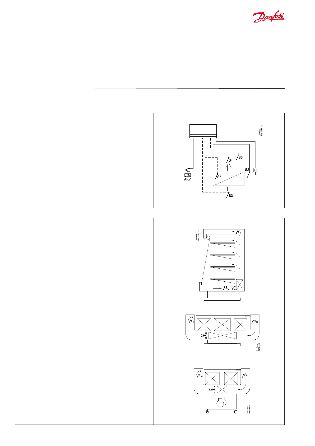
Principle
The temperature in the appliance is registered by one or two
temperature sensors which are located in the air ow before the
evaporator (S3) or after the evaporator (S4) respectively. A setting
for thermostat, alarm thermostat and display reading determines
the inuence the two sensor values should have for each individual function.
In addition product sensor S6, which can be optionally placed in
the appliance, can be used to register the temperature near the
required product in a certain place within the appliance.
The temperature of the evaporator is registered with the S5 sensor
which can be used as a defrosting sensor.
In addition to the outlet to the electronic injection valve of the
type AKV, the controller has 5 relay outputs which are dened by
the use selected – the individual usage options are described in
detail on page 12.
Operation ……………………………………………………………………………………………. 26
Menu survey ………………………………………………………………………………………..28
Connections ……………………………………………………………………………………….. 32
Data ……………………………………………………………………………………………………… 34
Ordering ………………………………………………………………………………………………35
Functions
• Day/night thermostat with ON/OFF or modulating principle
• Product sensor S6 with separate alarm limits
• Switch between thermostat settings via digital input
• Adaptive control of superheat
• Adaptive defrosting based on evaporator performance
• Start of defrost via schedule, digital input or network
• Natural, electric or hot gas defrost
• Stop of defrost on time and/or temperature
• Coordination of defrosting among several controls
• Pulsing of fans when thermostat is satised
• Case cleaning function for documentation of HACCP procedure
• Rail heat control via day/night load or dew point
• Door function
• Control of two compressors
• Control of night blinds
• Light control
• Heat thermostat
• Factory calibration that will guarantee a better measuring accu-
racy than stated in the standard EN 441-13 without subsequent
calibration (Pt 1000 ohm sensor)
• Integrated MODBUS communication with the option of mounting a LonWorks or DANBUSS communication card
2 Manual RS8EN702 © Danfoss 2016-03 AK-CC 550
Appliance examples
Applications
Here is an overview of the controller’s usage options.
A setting will congure input and outputs so that the controller’s
operation interface is directed at the selected application.
The current settings for the respective uses can be found on page
28.
Application 1-8
These uses are applied to standard appliances or cold storage
rooms with one valve, one evaporator and one refrigeration section.
The sensors are used according to standard principles.
The output functions change depending on the selected application.
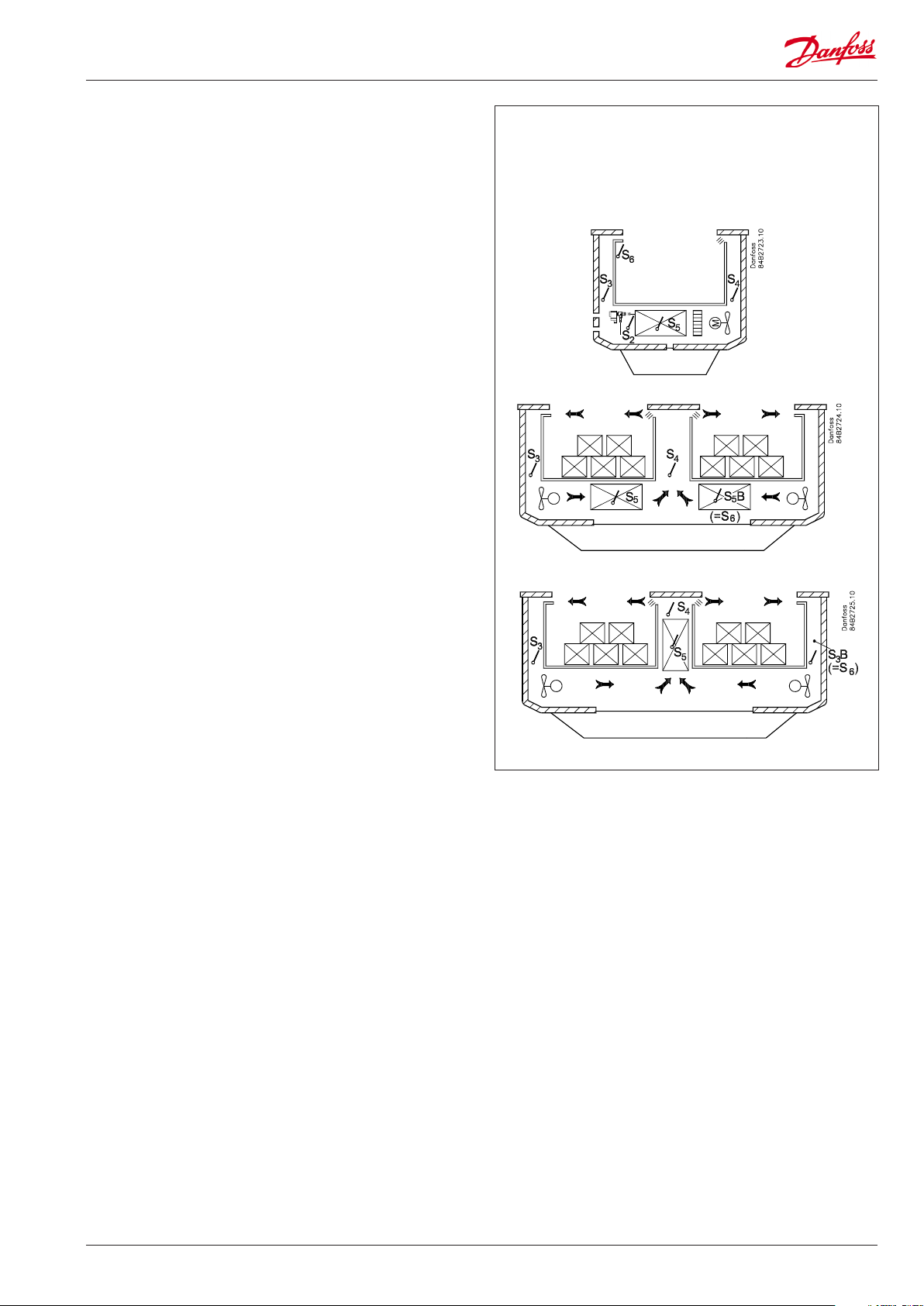
Application 9
This use is for refrigeration appliances with one valve, two evaporators and two refrigeration sections.
Here the temperature and alarm monitoring are always controlled
using the S4 sensor.
The S3 sensor is used for display readings.
The product sensor is replaced by an extra defrosting sensor S5B
for the second evaporator.
Application 10
This use is for refrigeration appliances with one valve, one evaporator and two refrigeration sections.
Here temperature is always controlled using the S4 temperature.
The S6 sensor is placed in the S3B position. The S3B sensor uses
alarm limits, etc which are normally used for the S6 sensor.
The two S3 temperatures are used for alarm monitoring and
display readings for each refrigeration section. There are separate
alarm limits for each refrigeration section.
AK-CC 550 Manual RS8EN702 © Danfoss 2016-03 3
Operation
Liquid injection
Liquid injection in the evaporator is controlled by an electronic
injection valve of the type AKV. The valve functions as both expansion valve and solenoid valve. The valve opens and closes using
signals from the controller.
The function contains an adaptive algorithm which independently
adjusts the valve’s opening so that the evaporator constantly supplies optimum refrigeration.
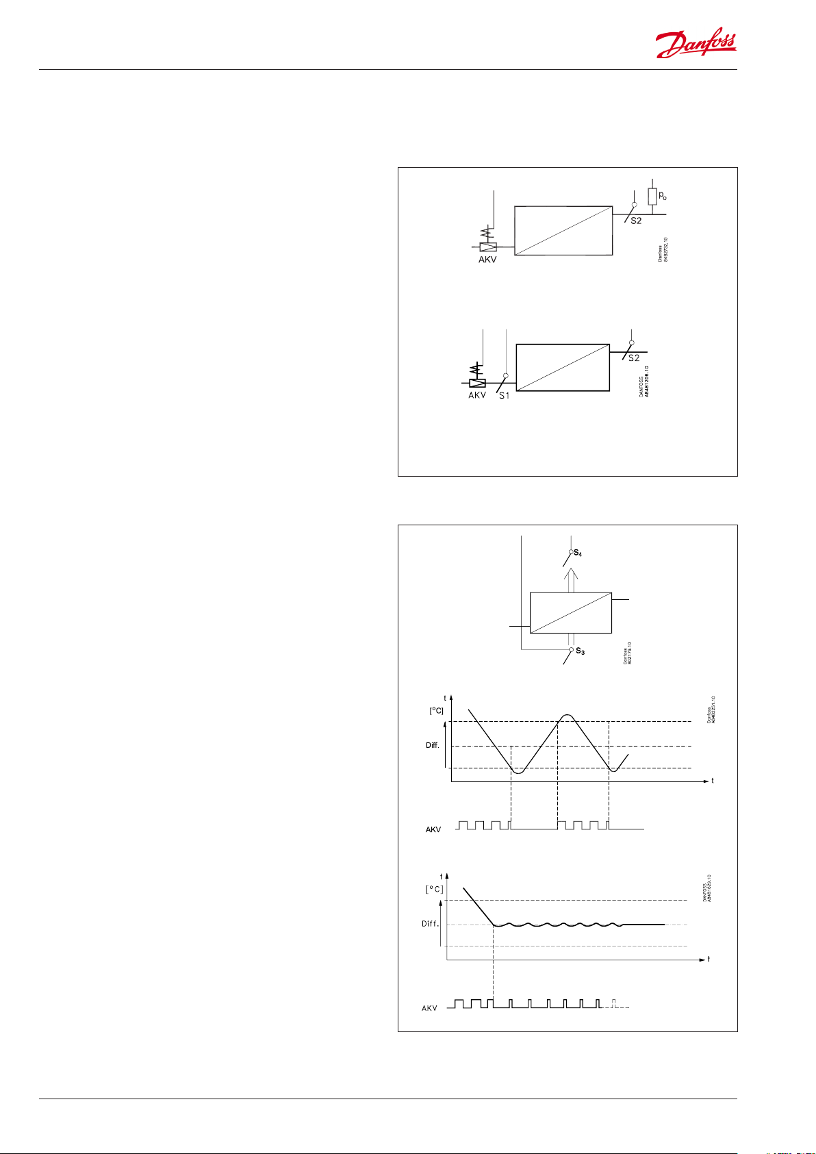
Superheat can be measured via one of the two following principles:
• Pressure sensor P0 and temperature sensor S2
For this use a correct measurement of superheat is achieved
under all conditions which ensures a very robust and precise
control.
The signal from one pressure transmitter can be used by several
controllers, but only if there is no signicant pressure dierence
between the evaporators in question.
• Two temperature sensors S1 and S2
Use of the S1 sensor means that location is particularly important. The sensor must be located so as to read the evaporating
temperature during injection without the presence of too much
pressure drop. Danfoss recommends that the S1 sensor be
located on the rst pipe bend on the evaporator.
Placement of the S1 sensor is crucial for a safety signal
and with this a satisfactory control.
Temperature control
The temperature in the appliance is registered by one or two
temperature sensors which are located in the air ow before the
evaporator (S3) or after the evaporator (S4) respectively. A setting
for the thermostat, alarm thermostat and display reading determines how much the two sensor values should inuence each
individual function, e.g. 50% will produce an equal value from
both sensors.
The actual temperature control can take place in two ways: as an
ordinary ON/OFF regulation with a dierential, or as a modulating control there the temperature variation will not be nearly as
great as in ON/OFF control. There is however a limit to the use of
a modulating control as it can only be used in central plant. In a
decentralised plant the thermostat function with ON/OFF control
should be selected.
In a central plant the thermostat function may either be selected
for ON/OFF control or modulating control.
Temperature monitoring
Just as is possible for the thermostat, the alarm monitoring can be
set with a weighting between S3 and S4 so that you can decide
how much the two sensor values should inuence the alarm
monitoring. Minimum and maximum limits can be set for alarm
temperature and time delays. A longer time delay can be set for
high temperature alarms. This time delay is applicable during
defrosting, appliance cleaning and start-up.
4 Manual RS8EN702 © Danfoss 2016-03 AK-CC 550
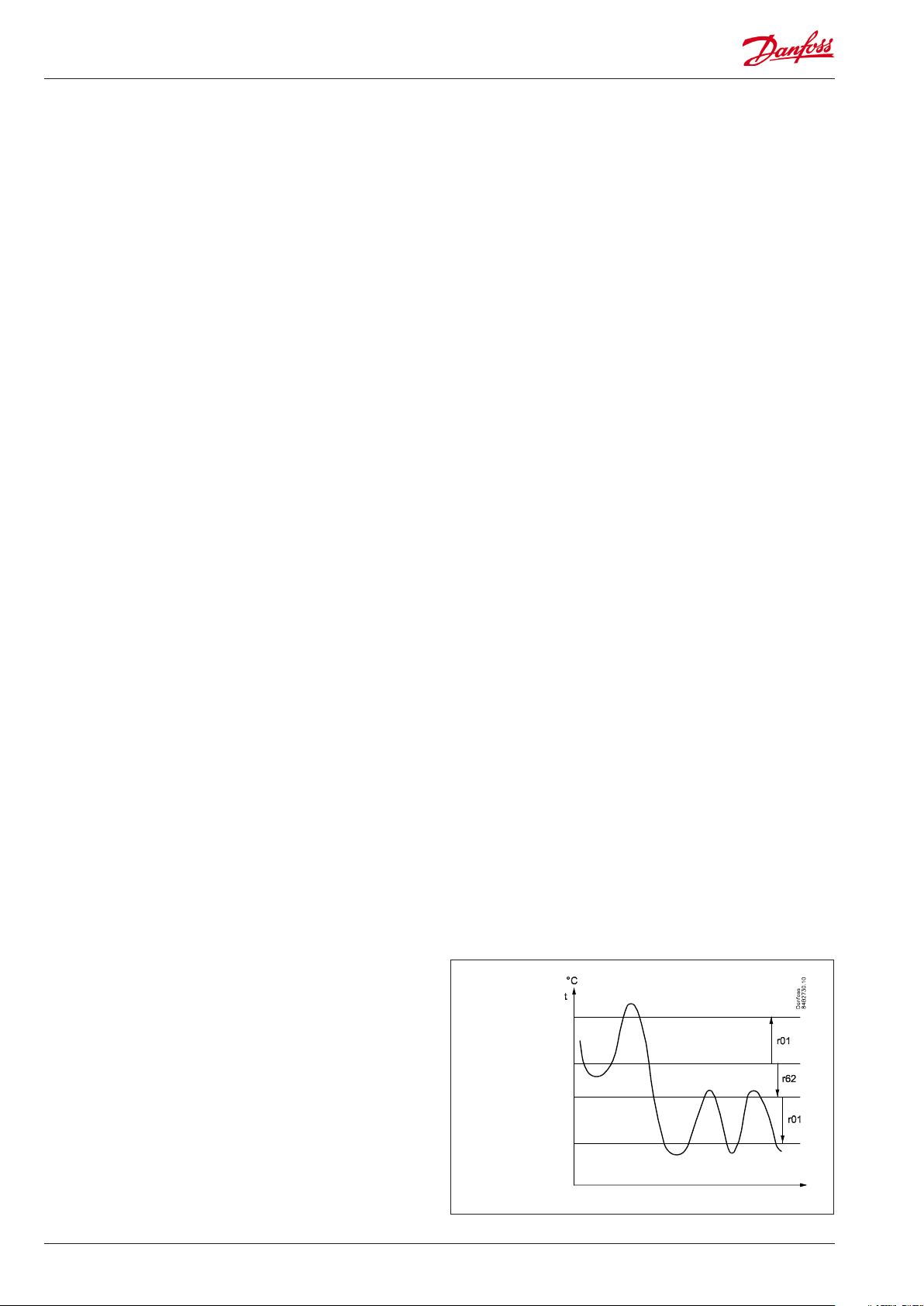
Thermostat bands
Thermostat bands can be used benecially for appliances where
dierent product types are stored which require dierent temperature conditions. It is possible to change between the two
dierent thermostat bands via a contact signal on a digital input.
Separate thermostat and alarm limits can be set for each thermostat band – also for the product sensor.
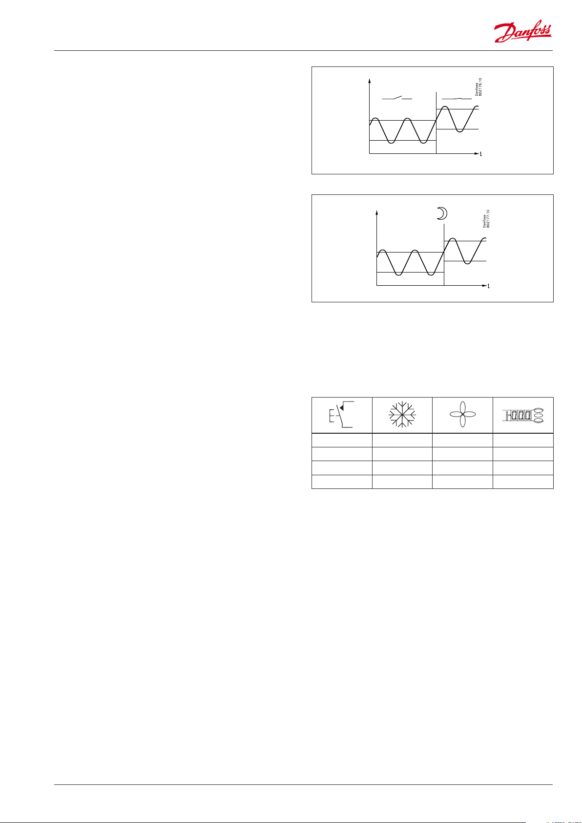
Night setback of thermostat value
In refrigeration appliances there may be big load dierences
between the shop’s opening and closing hours, especially if night
lids/blinds are used. The thermostat reference may be raised here
without it having any eect on the product temperature.
Change-over between day and night operation can take place, as
follows:
• via an external switch signal.
• via a signal from the data communication system.
Product sensor
A separate optional product sensor S6, which may be placed
in the appliance, can also be used and which can register and
monitor the temperature in the warmest part of the appliance.
There are separate alarm limits and time delays for the product
sensor.
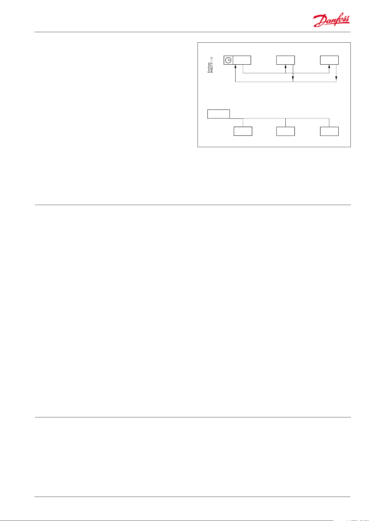
Appliance cleaning
This function makes it easy for the shop’s sta to carry out a
cleaning of the appliance according to a standard procedure.
Appliance cleaning is activated via a signal – as a rule via a key
switch placed on the appliance.
Appliance cleaning is carried out via three phases:
1 — at the rst activation the refrigeration is stopped, but the fans
keep on operating in order to defrost the evaporators. ”Fan” is
shown on the display.
2 — at the second activation the fans are also stopped and the
appliance can now be cleaned. ”OFF” is shown on the display.
3 — At the third activation refrigeration is recommenced. The
display will show the actual appliance temperature, (o97
setting).
When appliance cleaning is activated a cleaning alarm is transmitted to the normal alarm recipient. A later processing of these
alarms will document that the appliance has been cleaned as
often as planned.
Alarm monitoring
There are no temperature alarms during appliance cleaning.
— + + °C
1 ÷ + Fan
2 ÷ ÷ O
3 + + °C
AK-CC 550 Manual RS8EN702 © Danfoss 2016-03 5
Defrost
Depending on the application you may choose between the following defrost methods:
Natural: Here the fans are kept operating during the defrost
Electric: The heating element is activated
Hotgas: Here the solenoid valves are controlled so that the
hotgas can ow through the evaporator
Defrost sequence
1) Pump down
2) Defrost
3) Waiting position after defrost
4) Draining (drain delay. Hotgas only)
5) Drip o
6) Delay of fan
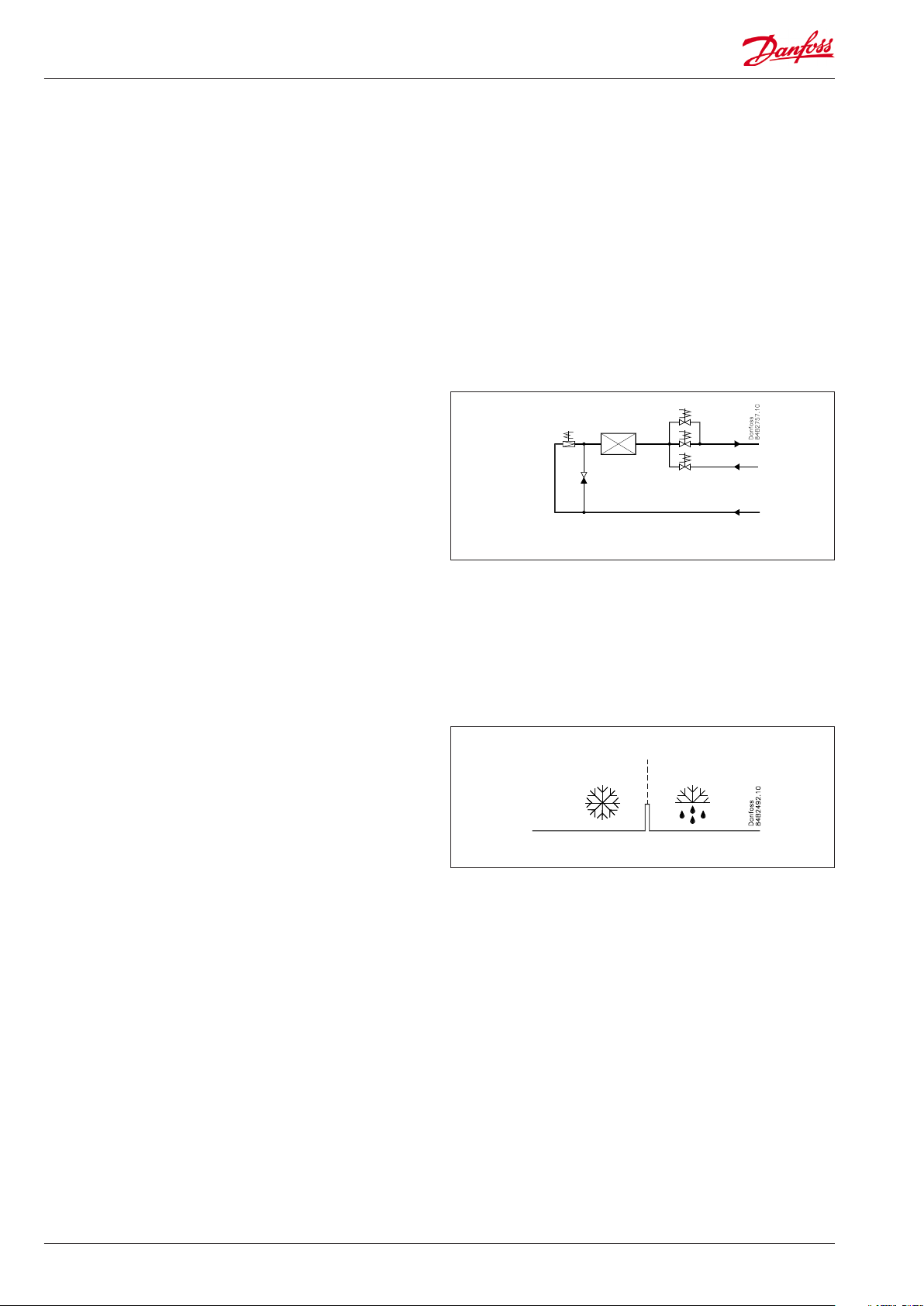
Hot gas defrost (application 6 only)
This type of connection can be used on systems with hotgas
defrost, but only in small systems in, say, supermarkets – the
functional content has not been adapted to systems with large
charges
Relay 2 is used for suction valve
Relay 4’s change-over function can be used by the bypass valve
and/or the hotgas valve.
Must not be used together with PMLX and GPLX valves, unless a
time delay relay is installed, which ensures that the PMLX/GPLX
valve is closed completely before the hotgas is turned on.
Hot gas application
Drip tray heating element
It is possible to control a heating element in the drip tray for
hot gas defrosting. When defrosting is commenced, the heating
element is activated. The heating element remains activated until
a set time after defrosting has ended by time or temperature.
Start of defrost
A defrost can be started in dierent ways
Interval: Defrost is started at xed time intervals, say, every
eighth hour. An interval must ALWAYS be set to
a «higher» value than the period set between two
defrostings when a schedule or network signal is used.
Refrigeration time: Defrost is started at xed refrigeration time
intervals, in other words, a low need for refrigeration will
”postpone” the defrost
Schedule: Here defrost can be started at xed times of the
day and night. However, max. 6 times
Contact: Defrost is started with a contact signal on a digital input
Network: The signal for defrost is received from a system unit
via the data communication
Adaptive defrost: Here defrosting is started based on intelligent
registering of evaporator performance.
Manual: An extra defrost can be activated from the controller’s
lower-most button
All the mentioned methods can be used at random – if just of
them is activated a defrost will be started.
Stop of defrost
Defrosting can be stopped by either:
• Time
• Temperature (with time as safety).
6 Manual RS8EN702 © Danfoss 2016-03 AK-CC 550
Coordinated defrost
There are two ways in which coordinated defrost can be arranged.
Either with wire connections between the controllers or via data
communication
Wire connections
The digital input DI2 is connected between the current controllers.
When one controller starts a defrost all the other controllers will
follow suit and likewise start a defrost. After the defrost the individual controllers will move into waiting position. When all are in
waiting position there will be a change-over to refrigeration.
Coordination via data communication
Here the system unit handles the coordination.
The controllers are gathered in defrosting groups and the system
unit ensures that defrosting is started in the group according to a
weekly schedule.
When a controller has completed defrosting, it sends a message
to the system unit and then goes into a waiting position. When
every controller in the group is in a waiting position, refrigeration
is again permitted in all the individual controllers.
Max. 10
System manager
Defrost on demand
1 Based on refrigeration time
When the aggregate refrigeration time has passed a xed time,
a defrost will be started.
2 Adaptive defrosting based on monitoring of evaporator per-
formance
This function is based on a registration of the air ow through
the evaporator. By using the AKV valve as mass owmeter for the
refrigerant ow it is possible to compare the energy input on the
refrigerant side with the energy output on the air side. Via this
comparison the air ow through the evaporator can be deter-
mined and hence also the amount of ice/frost build-up on the
evaporator surface. If the ice/frost build-up reduces the capac-
ity of the evaporator the function will carry out an additional
defrost.
Enter in the weekly defrost schedule the number of defrosts
corresponding to the basic load. If the load of the evaporator is
increased beyond this, defrost on demand will add the required
additional defrosts.
The function requires the following connections:
— Expansion valve type AKV
— Temperature signal from both S3 and S4
— Temperature signal from the condensing pressure Tc which is to
be distributed via the network from the system manager. If the
controller can not load the Tc signal, the measurement is replaced by a constant.
NOTE. The S3 and S4 sensors must be placed in the air ow/channel immediately before/after the evaporator.
Min. time between defrosts
There is a 2 hours minimum time between defrosts.
This avoids that planned defrosts in accordance with the weekly
schedule are carried out immediately after a defrost on demand
has been carried out. The time applies from when a defrost on
demand has been completed to when a planned defrost is again
permitted. The defrost on demand will not start defrosting with a
shorter interval than the 2 hours either.
Reset
If the adaptive defrost function registers problems with the
defrost, it will show an error message and the function will no
longer carry out extra defrosts. In this event a manual reset of the
function via d22 should be carried out.
When the reset function is activated it will start a defrost so that
the subsequent tuning will take place on an evaporator with no
ice/frost build-up.
Note
The function «Adaptive defrost” should only be activated when the
evaporator runs under normal operational conditions.
Melting function
This function will stop the air ow in the evaporator from being reduced by frost created by uninterrupted operation for a long time.
The function is activated if the thermostat temperature has
remained in the range between -5°C and +10°C for a longer
Real-time clock
The controller has a built-in real-time clock which can be used to
start defrosts. This clock has a power reserve of four hours.
If the controller is equipped with data communication, the clock
will automatically be updated from the system unit.
period than the set melting interval. The refrigeration will then be
stopped during the set melting period. The frost will be melted
so that the air ow and hence the evaporator’s capacity will be
greatly improved.
AK-CC 550 Manual RS8EN702 © Danfoss 2016-03 7
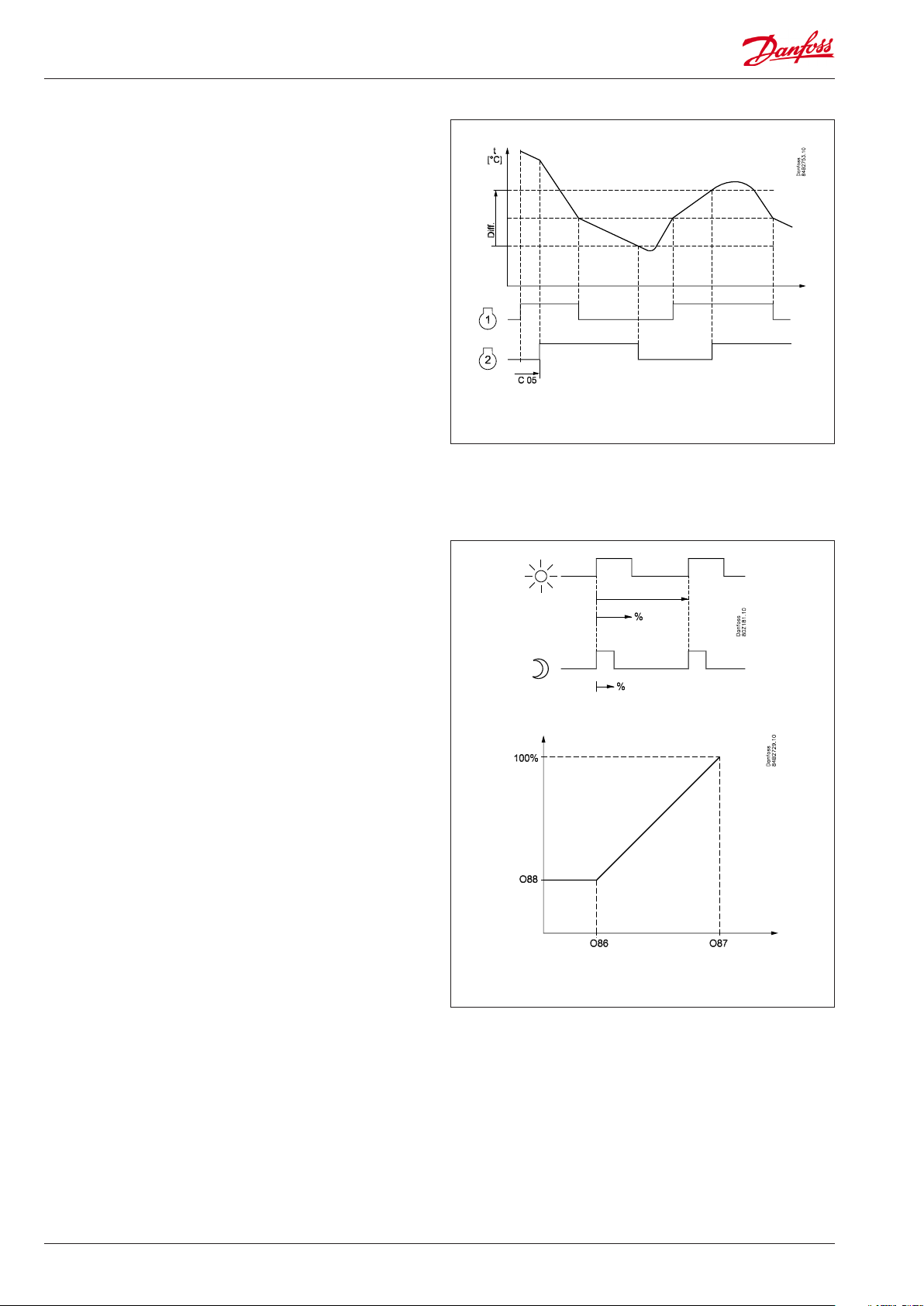
Control of two compressors
The two compressors must be of the same size. When the controller demands refrigeration it will rst cut in the compressor with
the shortest operating time. After the time delay the second
compressor will be cut in.
When the temperature has dropped to ”the middle of the dierential”, the compressor with the longest operation time will be cut
out.
The running compressor will continue until the temperature has
reached the cutout value. Then it will cut out. When the temperature again reaches the middle of the dierential, a compressor will
again be started.
If one compressor cannot maintain the temperature within the
dierential, the second compressor will also be started.
If one of the compressors has run on its own for two hours, the
compressors will be changed over so that operational time is balanced.
The two compressors must be of a type that can start up against a
high pressure.
The compressors’s settings for ”Min On time” and ”Min O time”
will always have top priority during normal regulation. But if one
of the override functions is activated, the ”Min On time” will be
disregarded.
Railheat
It is possible to pulse-control the power to the rail heat in order to
save energy. Pulse control can either be controlled according to
day/night load or dew point.
Pulse control according to day and night
Various ON periods can be set for day and night operation.
A period time is set as well as the percentage part of the period in
which the rail heat is ON.
Pulse control according to dew point
In order to use this function a system manager of the type AK-SM
is required which can measure dew point and distribute the current dew point to the appliance controllers. For this the rail heat’s
ON period is controlled from the current dew point.
Two dew point values are set in the appliance control:
• One where the eect must be max. i.e.100%. (o87)
• One where the eect must be min. (o86).
At a dew point which is equal to or lower than the value in 086,
the eect will be the value indicated in o88.
In the area between the two dew point values the controller will
manage the power to be supplied to the rail heat.
During defrosting
During defrosting the rail heat will always be 100% ON.
Rail heat
Dew point
8 Manual RS8EN702 © Danfoss 2016-03 AK-CC 550
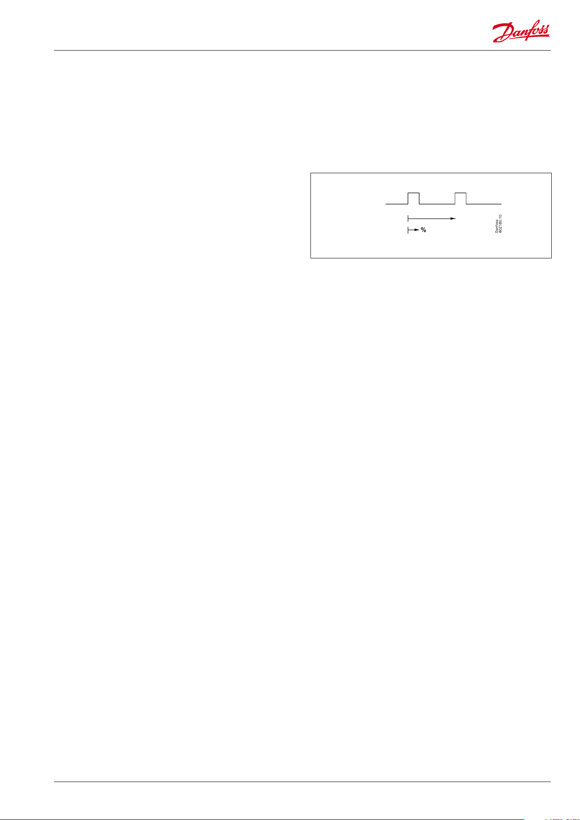
Fan
Pulse control
To obtain energy savings it is possible to pulse control the power
supply to the fans at the evaporators.
Pulse control can be accomplished in one of the following ways:
— during the thermostat’s cutout period (cold room)
— during night operation and during the thermostat’s cutout pe-
riod (appliance with night lid)
(This function is not present when r14 = 2, i.e. modulating regula-
tion.)
A period of time is set as well as the percentage of this period of
time where the fans have to be operating.
Cutout of fans during plant breakdowns
If the refrigeration in a breakdown situation stops, the
temperature in the cold room may rise quickly as a result of the
power supply from large fans. In order to prevent this situation the
controller can stop the fans if the temperature at S5 exceeds a set
limit value.
Light function
The function can be used for controlling the light in a refrigeration
appliance or in a cold room. It can also be used for controlling a
motorised night blind.
The light function can be dened in three ways:
— the light is controlled via a signal from a door contact. Together
with this function a time delay can be set so that the light is kept
on for a period of time after the door has been closed.
— the light is controlled via the day/night function
— the light is controlled via the data communication from a system
unit.
Here there are two operational options if data communication
should fail:
— The light can go ON
— The light can stay in its current mode.
The light load must be connected to the NC switch on the relay.
This ensures that the light remains on in the appliance if power to
the controller should fail.
The light is switched o when «r12» (Main switch) is set to o (see
o98).
The light is switched o when the appliance cleaning function is
activated.
Night blind
Motorised night blind can be controlled automatically from the
controller. The night blinds will follow the status of the light
function. When the light is switched on, the night blinds opens
and when the light is switched o, the night blinds close again.
When the night blinds are closed, it is possible to open them using
a switch signal on the digital input. If this input is activated, the
night blinds will open and the refrigeration appliance can be lled
with new products. If the input is activated again, the blinds close
again.
When the night blind function is used, the thermostat function
can control with dierent weighting between the S3 and S4
sensors. A weighting during day operation and another when the
blind is closed.
A night blind is open when the appliance cleaning function is
activated.
A setting can dene that the night blind is open when «r12» (Main
switch) is set to o (see o98).
AK-CC 550 Manual RS8EN702 © Danfoss 2016-03 9
Digital inputs
There are two digital inputs DI1 and DI2 with contact function and
one digital input DI3 with high voltage signal.
They can be used for the following functions:
— Retransmission of contacts position via data communication
— Door contact function with alarm
— Starting a defrost
— Main switch — start/stop of cooling
— Night setback
— Thermostat bands switch
— General alarm monitoring
— Case cleaning
— Forced cooling
— Override of night blinds
— Coordinated defrost (DI2 only)
— Forced closing of valve (DI 3 only)
Forced closing
The AKV valves can be closed with an external signal ( «Forced
closing»).
The function must be used in connection with the compressor’s
safety circuit, so that there will be no injection of liquid into the
evaporator when the compressor is stopped by the safety controls. (However not at low pressure – LP).
If a defrost cycle is in progress, the forced closing status will not be
re-established until the defrost is completed.
The signal can be received from the DI3-input or via the data communication.
During a forced closing the fans can be dened to be stopped or
in operation.
Door contact
The door contact function can via the digital inputs be dened for
two dierent applications:
Alarm monitoring
The controller monitors the door contact and delivers an alarm
message if the door has been opened for a longer period than
the set alarm delay.
Alarm monitoring and stop of refrigeration
When the door is opened the refrigeration is stopped, i.e. the
injection, the compressor and the fan are stopped and light
switch on.
If the door remains open for a longer time than the set restart
time, refrigeration will be resumed. This will ensure that
refrigeration is maintained even if the door is left open or if the
door contact should be defective. If the door remains open for
a longer period than the set alarm delay an alarm will also be
triggered.
Heating function
The heating function is used to prevent the temperature
becoming too low, e.g. in a cutting room, etc. The limit for when
the heating function cuts o is set as an oset value under the
current cutout limit for the refrigeration thermostat. This ensures
that refrigeration and heating do not occur simultaneously.
The dierence for the heating thermostat has the same value
as for the refrigeration thermostat. To prevent that the heating
thermostat cuts in during short-term drops in air temperature a
time delay can be set for when to change from refrigeration to
heating.
Refrigeration
Neutral zone
Heat
10 Manual RS8EN702 © Danfoss 2016-03 AK-CC 550
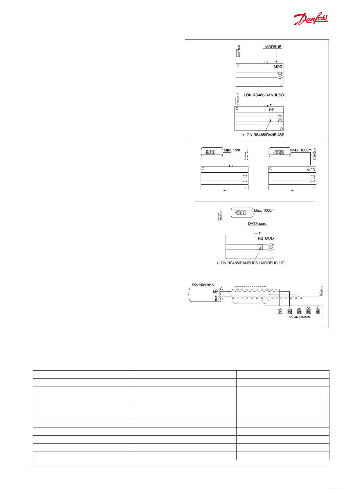
Data communication
The controller has xed built-in MODBUS data communication.
If there is a requirement for a dierent form of data
communication, a Lon RS 485 or DANBUSS module can be
inserted in the controller.
The connection must then be to terminal RS 485.
(To use a Lon RS 485 module and gateway type AKA 245 the
module must be Version 6.20 or higher.)
Display
The controller has one plug for a display. Here display type EKA
163B or EKA 164B (max. length 15m) can be connected.
EKA 163B is a display for readings.
EKA 164B is both for readings and operation.
The connection between display and controller may be with a
cable which has a plug at both ends.
If the distance between display and controller is greater than 15
Address o03 > 0
m, the connection must take another form.
An extra module must also be mounted in the controller if data
communication is used.
The built-in MODBUS data communication is used so that the
display connection and the data communication to the other
controllers must take place via a module. The module can be:
Lon RS 485, DANBUSS or MODBUS.
When a display is to be connected to the built-in MODBUS, the
display can advantageously be changed to one of the same type,
but with Index A (version with screw terminals).
The controllers address must be set higher than 0 in order for the
display to be able to communicate with the controller.
If connection of two displays is required, one must be connected
to the plug (max. 15 m) and the other must then be connected to
the xed data communication.
Important
All connections to the data communication MODBUS, DANBUSS
and RS 485 must comply with the requirements for data
communication cables. See literature: RC8AC.
Override
The controller contains a number of functions which can be used together with the override function in the master gateway/system
manager.
Function via data communication Function in gateway/system manager Used parameters in AK-CC 550
Start of defrosting Defrost control / Time schedule / Defrost group — Def start
Coordinated defrost Defrost control / Defrost group — HoldAfterDef / — — — DefrostState
Prevent defrost start — Disable Def
Day/Night schedule Day/Night control / Time schedule / Light zone — Night setback
Light control Day/Night control / Time schedule O39 light Remote
Forced closing Forced Close / Injection ON / AKC ON — Forced cl.
Forced cooling — Forced cool
Railheat link to dew point / Enhanced railheat — Dew point
P0 optimization P0 Optimization The controller supports P0 optimization
Adaptive defrost / Adaptive defrost. System manager only — — — Tc TempMean
AK-CC 550 Manual RS8EN702 © Danfoss 2016-03 11
Loading…
Контроллер Danfoss AK-CC 550 может применяться для управления торговым холодильным оборудованием и холодильными камерами всех типов. Преимуществами данного контроллера являются: быстрая настройка с использованием предварительно заданных параметров, встроенная плата передачи данных, встроенные часы с автономным питанием.
Документация
Температура охлаждаемого воздуха измеряется одним или двумя датчиками температуры, установленными в воздушном потоке перед испарителем (S3) или после него (S4). Показания датчиков определяют работу управляющего и аварийного термостатов и дисплея. Для регистрации температуры продукта можно установить дополнительный датчик S6. В качестве датчика оттаивания можно использовать датчик температуры испарителя S5. Кроме выхода на электронный расширительный клапан типа AKV, контроллер имеет 5 релейных выходов, функции которых определяются выбранным режимом работы.
Функции:
— Термостат дневного и ночного режимов с двухпозиционным (ВКЛ/ОТКЛ.) или плавным регулированием(модулирующий термостат).
— Аварийный датчик температуры продуктов S6 с индивидуальными пределами сигнализации.
— Переключение между диапазонами термостата через цифровой вход.
— Адаптивный контроль перегрева.
— Адаптивное оттаивание по обмерзанию испарителя.
— Начало оттаивания по графику, сигналу цифрового входа или по сети передачи данных.
— Естественное оттаивание, оттаивание с помощью электронагревателя или горячего газа.
— Конец оттаивания по времени или температуре.
— Координированное оттаивание нескольких контроллеров (master—slave).
— Включение вентиляторов по сигналам термостата.
— Функция уборки для документального подтверждения выполнения требований НАССР.
— Контроль кантового подогрева стекол по дневномуночному режиму или по точке росы.
— Аварийная сигнализация двери.
— Управление двумя компрессорами.
— Управление ночными шторками.
— Управление освещением.
— Функция подогрева.
— Заводская настройка, обеспечивающая повышенную точность измерения температуры по сравнению требованиями, приведенными в стандарте EN 441‑13 (с датчиком температуры Pt 1000 Ом).
— Встроенная плата передачи данных MODBUS с возможностью подключения сетевой карты LonWorks или Ethernet.
| Электропитание | 230 В пер. тока, +10/−15%, 5 ВА | |
| Датчик S2 | Pt 1000 | |
| Датчики S3, S4, S5, S6 | Pt 1000 или РТС 1000 Ом / 25 °С (Все датчики должны быть одного типа) | |
| Погрешность | Диапазон измерения | От —60 до +120 °С |
| Контроллер | ±1 К при темп. ниже −35 °С ±0,5 К при темп. от −35 до +25°С ±1 К при темп. выше +25 °С |
|
| Датчик Pt 1000 | ±0,3 К при темп. 0 °С ±0,005 К на град. |
|
| Измерение давления | Датчик давления | AKS 32R |
| Дисплей контроллера | Светодиодный, 3‑разрядный | |
| Внешний дисплей | ЕКА 163В или 164В (любой ЕКА 163А или 164А) | |
| Цифровые входы DI1, DI2 | Сигнал от контактных функций. Рекомендуется использовать позолоченные контакты. Длина кабелей не более 15 м. При большей длине кабелей используйте дополнительные реле | |
| Цифровой вход DI3 | 230 В пер. тока | |
| Соединительные кабели | Многожильные кабели сечением не более 1,5 мм2 | |
| Твердотельное реле | DO1 (для катушки AKV) | Макс. 240 В пер. тока, мин. 28 В пер. тока Макс. 0,5 А Утечки тока < 1 мА Макс. кол‑во AKV: 1 |
| Реле | СЕ (250 В пер. тока | |
| DO3, DO4 | 4 (3) А | |
| DO2, DO5, DO6 | 4 (3) А | |
| Параметры окружающей среды | Температура окр. воздуха при эксплуатации: от 0 до +55 °С. Температура окр. воздуха при транспортировке: от −40 до +70 °С | |
| Отн. влажность воздуха: от 20 до 80%, не допускать конденсации | ||
| Не подвергать ударам и вибрации | ||
| Степень защиты корпуса | IP 20 | |
| Монтаж | На рейке DIN или на стене | |
| Масса | 0,4 кг | |
| Передача данных | Встроенный блок | MODBUS |
| Сетевые карты | LON RS485 | |
| TCP/IP | ||
| MODBUS | ||
| Контроллер не может работать с блоком мониторинга типа m2 | ||
| Время работы часов с источником питания | 4 часа | |
| Соответствие документам | Соответствует требованиям работы с низковольтным оборудованием и требованиям на электромагнитную совместимость. Проверен на соответствие стандартам EN 60730‑1, EN 60730‑2‑9, A1, A2, EN50082‑1 и EN 60730‑2‑9, A2 |
Danfoss AK-CC 550 Controller PDF User Guides and Manuals for Free Download: Found (2) Manuals for Danfoss AK-CC 550 Device Model (Manual , Instructions Manual)
The Danfoss AK-CC 550 is an exceptional refrigeration controller designed for a wide array of applications. Its versatility and user-friendly features make it a favorable choice among professionals in the refrigeration industry. The product stands out due to its robust engineering, intuitive interface, and compatibility with various refrigerants. In this review, we will delve deeper into the specifications, features, and overall performance of the AK-CC 550.
One of the key highlights of the Danfoss AK-CC 550 is its comprehensive control capabilities. This product is engineered to manage refrigeration systems effectively, ensuring optimal temperature maintenance and energy efficiency. Users can easily monitor and adjust settings through the large LCD display, providing clear readability and straightforward navigation. The menu-driven configuration allows for quick adjustments and a more efficient setup process, which is particularly beneficial during installation.
Here are some crucial features of the Danfoss AK-CC 550:
- Multi-Functionality: The AK-CC 550 is designed to control various applications, including display cabinets, cold rooms, and transcritical systems. This adaptability makes it suitable for diverse market needs.
- Energy Efficiency: The controller promotes energy-saving strategies, which are increasingly important in today’s environmentally conscious market. It aids in reducing operational costs while maintaining performance.
- User-Friendly Interface: The intuitive user interface simplifies operation and programming. The clear display also helps to monitor performance with ease.
- Data Logging: The controller offers advanced data logging features to track system performance over time. This can be instrumental in preventive maintenance and troubleshooting potential issues before they become critical.
- Connectivity Options: The AK-CC 550 supports various connectivity options, making it compatible with numerous external monitoring systems and devices.
Performance-wise, the Danfoss AK-CC 550 excels in maintaining refrigeration accuracy. The feedback from industry professionals indicates that it reliably keeps temperatures within specified limits, improving product quality and safety. This is particularly vital in sectors such as food and beverage, where temperature fluctuations can lead to spoilage and financial losses.
Another noteworthy aspect is the reliability and durability of the AK-CC 550. Danfoss has applied rigorous quality standards in its production, ensuring that the controller can withstand the demanding conditions often found in refrigeration environments. This durability translates into lower maintenance needs, which is a significant advantage for businesses operating on tight budgets.
In conclusion, the Danfoss AK-CC 550 is a powerful tool that meets the needs of modern refrigeration systems. Its combination of functionality, user-friendliness, and durability makes it a standout in its category. Whether for commercial refrigeration applications or industrial uses, the AK-CC 550 is a valuable investment. Companies looking to enhance their refrigeration efficiency while minimizing energy costs should consider this product as a pivotal addition to their operations. Danfoss has certainly positioned the AK-CC 550 as a leading choice in the refrigeration control market, and it is sure to meet the demands of a diverse range of users.
More User Guides for Danfoss AK-CC 550:
-
Danfoss AK-CC 550 Manual (36 pages)
FAQ: Types of Manuals and Their Contents
Danfoss AK-CC 550 Manuals come in various types, each serving a specific purpose to help users effectively operate and maintain their devices. Here are the common types of Danfoss AK-CC 550 User Guides and the information they typically include:
- User Manuals: Provide comprehensive instructions on how to use the device, including setup, features, and operation. They often include troubleshooting tips, safety information, and maintenance guidelines.
- Service Instructions: Designed for technicians and repair professionals, these manuals offer detailed information on diagnosing and repairing issues with the device. They include schematics, parts lists, and step-by-step repair procedures.
- Installation Guides: Focus on the installation process of the device, providing detailed instructions and diagrams for proper setup. They are essential for ensuring the device is installed correctly and safely.
- Maintenance Manuals: Provide guidance on routine maintenance tasks to keep the device in optimal condition. They cover cleaning procedures, part replacements, and regular servicing tips.
- Quick Start Guides: Offer a concise overview of the essential steps needed to get the device up and running quickly. They are ideal for users who need immediate assistance with basic setup and operation.
Each type of Danfoss AK-CC 550 instruction is designed to address specific needs, ensuring users have the necessary information to use, maintain, and repair their devices effectively.
Related Instructions for Danfoss AK-CC 550:
1
VLT Soft Starter MCD 600
34
1229
271
2
VLT 6000
Installation manual Danfoss VLT 6000 User Guide (Installation manual), @SH382K
59
1266
203
3
FC 300
Manual Danfoss FC 300 User Manual (Manual ), @6E54TG
61
1130
204
4
FC 300
Instruction manual User Guide: Danfoss FC 300 (XLNC55, Upd.09th Jan 2025)
68
1014
203
6
EFET 130
Instruction EFET 130 (Thermostat ePDF User Manual, #J46H7F)
12
221
42
7
ECL Comfort 110
26
396
96
8
Akva Lux II TDP-F
36
771
193
9
VLT DriveMotor FCP 106
Programming manual #MZ7188: VLT DriveMotor FCP 106 Engine Programming manual
148
613
148
10
ECL Comfort 310, A333
20
988
218
Controller Devices by Other Brands:
|
Graco Pro Xpc 24Y307 Instructions Manual Graco Pro Xpc 24Y307 User Manual (Instructions manual), @KTP3AA Instructions 30 Jan 2025 | 66 |
|
|
ESBE CRA122 Series Quick Start Manual CRA122 Series Quick start manual — QB8AUK Mtrl.nr. 98140911• Ritn.nr. 8412 utg. A • Rev. 1505 22 Oct 2024 | 4 |
|
|
KMC Controls CSC-2000 Series Application Manual KMC Controls Controller Application manual (File: kmc-controls-csc-2000-series-application-manual-3, Saturday 03-05-2025) Replacing CSC-1001 with CSC-2000/3000 Series Controllers 03 May 2025 | 3 |
|
|
wohner MOTUS 0.075 – 0.6A Operating Instructions Manual #667Q58: MOTUS 0.075 – 0.6A Controller Operating instructions manual MOTUS® 16 Feb 2025 | 43 |
Categories:
Transducer
Radio
Heater
Water Heater Accessories
Heating Pad
Racks & Stands