
Service Manual
S/N No. :
Sep. 2002
ELECTRONICS CO., LTD.
Mini Component System
Model:
AMI-729L/R
AMI-829L/R

MINI COMPONENT SYSTEM
AMI-729L/R
AMI-829L/R
Table of Contents
SAFETY PRECAUTIONS…………………………………………………………………………….. 2
ADJUSTMENTS…………………………………………………………………………………………. 4
EXPLODED VIEW AND PARTS LIST ……………………………………………………………. 5
WIRING DIAGRAM ……………………………………………………………………………………… 8
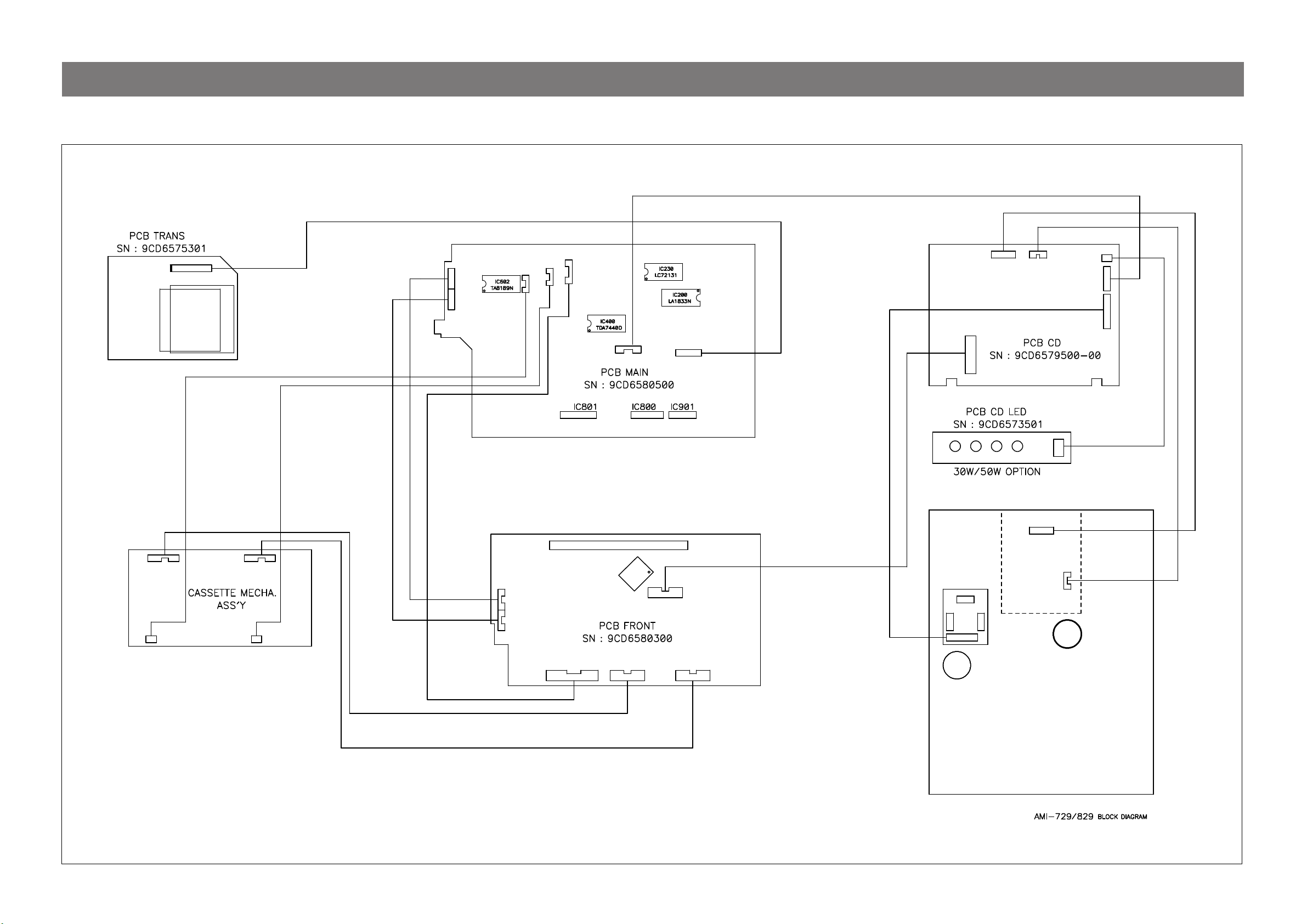
BLOCK DIAGRAM ………………………………………………………………………………………. 9
SCHEMATIC DIAGRAM ………………………………………………………………………………. 10
POWER / AMP /TUNER / TAPE ………………………………………………………………………………………. 10
CD …………………………………………………………………………………………………………………………………. 11
CONTROL ………………………………………………………………………………………………………………………. 12
PCB PATTERN LAYOUT ……………………………………………………………………………. 13
ELECTRICAL PART LIST …………………………………………………………………………… 17
— 1 —
Safety Precautions
WARNING
THIS APPLIANCE TO RAIN OR MOISTURE.
CAUTION :
TO PREVENT ELECTRIC SHOCK, DO NOT USE THIS POLARIZED AC
PLUG WITH AN EXTENSION CORD, RECEPTACLE OR OTHER OUTLET
UNLESS THE BLADES CAN BE FULLY INSERTED TO PREVENT BLADE
EXPOSURE.
THIS UNIT EMPLOYS A LASER. ONLY QUALIFIED SERVICE PERSONNEL
SHOULD REMOVE THE COVER OR ATTEMPT TO SERVICE THIS DEVICE
DUE TO POSSIBLE EYE INJURY.
CAUTION :
OTHER THAN THOSE SPECIFIED HEREIN MAY RESULT IN HAZARDOUS
RADIATION EXPOSURE.
CAUTION :
PLUG TO WIDE SLOT, FULLY INSERT.
ATTENTION :
LA LAME LA PLUS LARGE DE LA FICHE DANS LA BORNE CORRESPONDANTE DE LA PRISE ET POUSSER JUSQU’AU FOND.
: TO PREVENT FIRE OR ELECTRIC SHOCK, DO NOT EXPOSE
CAUTION
RISK OF ELECTRIC SHOCKS
DO NOT OPEN
TO REDUCE THE RISK IF ELECTRIC SHOCK, DO NOT
REMOVE COVER (OR BACK). NO USER SERVICEABLE PARTS
INSIDE.
REFER SERVICING TO QUALIFIED SERVICE PERSONNEL.
THIS SYMBOL IS INTENDED TO ALERT THE USER TO THE
PRESENCE OF UNINSULTED «DANGEROUS VOLTAGE»
WITHIN THE PRODUCT’S ENCLOSURE THAT MAY BE
SUFFICIENT MAGNITUDE TO CONSTITUTE A RISK OF
ELECTRIC SHOCK TO PERSONS.
THIS SYMBOL IS INTENDED TO ALERT THE USER TO THE
PRESENCE OF IMPORTANT OPERATING AND MAINTENANCE
(SERVICING) INSTRUCTIONS IN THE LITERATURE
ACCOMPANYING THE APPLIANCE.
CAUTION
LASER SAFETY
USE OF ANY CONTROLS, ADJUSTMENTS, OR PROCEDURES
TO PREVENT ELECTRIC SHOCK, MATCH WIDE BLADE OF
POUR EVITER LES CHOCS ELECTRIQUES, INTRODUIRE
Important Safety Instructions
— All the safety and operating instructions should be read before
the appliance is operated.
— The safety and operating instructions should be retained for
future reference.
— All warnings on the appliance and in the operating instructions
should be adhered to.
— All operating and use instructions should be followed.
1. Water and Moisture — The appliance should not be
water — for example, near a bathtub, washbowl, kitchen sink,
used near
laundry tub, in a wet basement, or near a swimming pool,
and the like.
PORTABLE CART
Figure 2
only as recommended by the manufacturer.
ceiling
5. Ventilation — The appliance should be situated so
location or position does not interfere with
ventilation. For example, the appliance
on a bed, sofa, rug, or
ventilation
as a bookcase or cabinet that may impede the flow
through the ventilation openings.
6. Heat — The appliance should be situated away from
sources such as radiators, heat registers,
appliances (including amplifiers) that
7. Power Sources — The appliance should be
power supply only of the type
instructions or as marked
8. Grounding or Polarization — The precautions that
taken so that the grounding or
appliance is not defeated.
9. Power — Cord Protection — Power-supply cords
routed so that they are not likely to be
by items placed upon or
attention to cords at
point where
10.Protective Attachment Plug — The appliance is equipped with
an attachment plug having overload
safety feature.
resetting of
required, be sure the
replacement plug
same overload protection as the original plug.
11.Cleaning — The appliance should be cleaned only as
recommended by the manufacturer.
12.Power Lines — An outdoor antenna should be located
from power lines.
openings; or, placed in a built-in installation, such
protective device. If replacement of the plug is
2. Carts and Stands — The appliance
should be used only with a cart or
stand that is recommended by th
manufacturer.
3. An appliance and cart combination
should
be moved with care. Quick
stops, excessive force, and uneven
surfaces may cause the appliance
and
cart combination to overturn.
4. Wall or Ceiling Mounting — The appli-
ance
should be mounted to a wall or
its proper
should not be situated
similar surface that may block the
stoves, or other
produce heat.
connected to a
described in the operating
on the appliance.
polarization means of an
walked on or pinched
against them, paying particular
plugs, convenience receptacles, and the
they exit from the appliance.
protection. This is a
See Instruction Manual for replacement or
service technician has used a
specified by the manufacturer that has the
that its
should be
should be
of air
heat
away
— 2 —
Safety Precautions
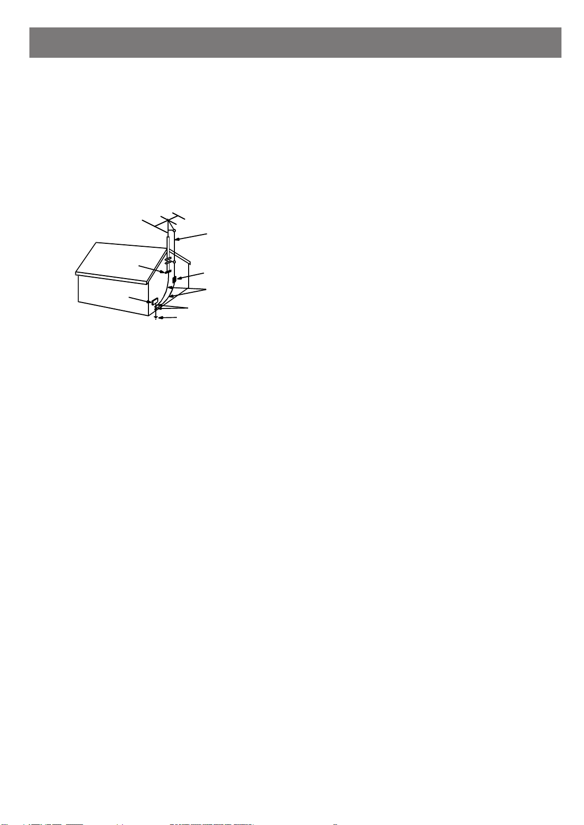
13.Outdoor Antenna Grounding — If an outside antenna
connected to the receiver be sure the antenna
system is
grounded so as to provide some protection against voltage
surges and built-up static
Electrical Code,
regard to
proper grounding of the mast and supporting
charges. Article 810 of the National
ANSI/NFPA 70, provides information with
structure, grounding of the lead-in wire to an antenna-dis
charge unit, size of grounding conductors,location of antennadischarge unit, connection to grounding electrodes and
requirements for the grounding electrode. See Figure 1.
EXAMPLE OF ANTENNA
GROUNDING
GROUND CLAMP
ELECTRIC
SERVICE
EQUIPMENT
NEC — NATIONAL ELECTRICAL CODE
POWER SERVICE GROUNDING
ELECTRODE SYSTEM
(NEC ART 250 PART H)
ANTENNA LEAD
IN WIRE
ANTENNA DISCHARGE UNIT
(NEC SECTION 810-20)
GROUNDING CONDUCTORS
(NEC SECTION 810-21)
GROUND CLAMPS
14.Non-use Periods — The power cord of the appliance should be
unplugged from the outlet when left
unused for a long period
of time.
is
15.Object and Liquid Entry — Care should be taken so
that objects
do not fall and liquids are not spilled into the enclosure through
openings.
16.Damage Requiring Service — The appliance should
be
serviced by qualified service personnel when:
a) The power-supply cord or the plug has been
b) Objects have fallen, or liquid has been spilled
damaged; or
into the
appliance; or
c) The appliance has been exposed to rain; or
d) The appliance does not appear to operate
exhibits a marked change in
performance; or
e) The appliance has been dropped, or the
normally or
enclosure
damaged.
17.Servicing — The user should not attempt to service the
appliance beyond that described in the operating instructions.
All other servicing
should be referred to qualified service
personnel.
— 3 —
Adjustments
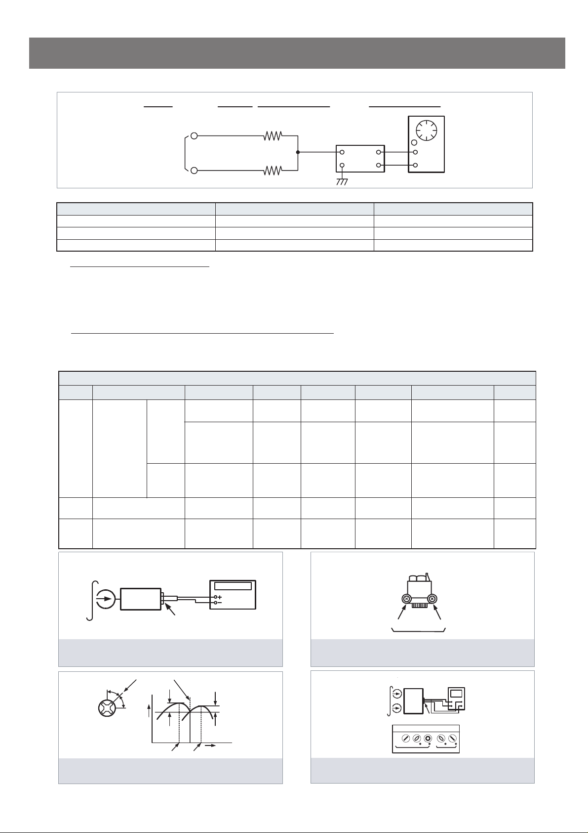
TAPE SECTION
Input Level
Measurement
Point
Output Level
Measurement
Point
R-CH
47 kohm
Input Point
VTVM
Scope
L-CH
47 kohm
Test Tape be used
Tape Contents Use
MTT-111N 3 KHz Tape Speed Adjustment
MTT-114N 10 KHz Head Azimuth Adjustment
MTT-5511 Blank Record Frequency Property
HEAD ADJUSTMENT (AZIMUTH)
1. 10KHz test tape(example: MTT-114N) must be used for this adjustment.
2. Connect to VTVM or oscilloscope to the headphone jack or speaker terminal.
3. Press the play button.
4. Adjust the azimuth by using a screw driver to maintain the max. L&R output voltage.
5. Adjust tape A(1), tape B(2) respectively, Please secure the azimuth position by using locking paint.
RECORDING BIAS OSCILLATOR FREQUENCY ADJUSTMENT
1. Connect the frequency counter to TP603, GND.
2. Press the REC button.
3. Adjust L603 to obtain 80 KHz
Step Item Reference Value Test Tape Adjust Point Test Point Note FIG.
Normal
Tape Speed
1
Adjustment
High
2
Azimuth Adjustment
Recording Bias Oscilla-
tor Frequency Adjust-
3
ment
±
100Hz
TAPE ALIGNMENT CHART
3,015~3,025Hz MTT-111N RV601
3,000~3,010Hz MTT-111N RV601
5,820~6,180Hz MTT-111N — — — — — —
Maximum Level
Phase:Within90°
80 KHz±0.5
MTT-114N Head Screw
MTT-5511 L603
Line Out L/R
Channel
Line Out L/R
Channel
Shorted
TP601,
TP602
Line Out L/R
Channel
TP603,GND
Confirm Wow & Flutter is within 0.35%
Confirm Tape Speed
of end position after
adjustment at tape
start position
Confirm High speed
after normal speed
adjustment
Adjust with frequency
counter connected.
FIG.1
FIG.1
FIG.1
FIG.2,3,4
FIG.1
Adjust with Frequency
Test Tape : MTT-111N(3kHz)
MTT-5511(Blank)
Set
Frequency Counte
Output Level
Measurement Point
FIG. 1 : Tape Speed & Record Bias Oscillator
Frequency Adjust Circuit
L-CH
Screw
Angle
Peak
R-CH
Peak
within
1 dB
Output Level
L-CH
Peak
R-CH
Peak
within
1 dB
Screw Angle
FIG. 3 : Tape Azimuth Adjust Head Screw & Waveform
FIG. 2 : Tape Azimuth Adjust Location
FIG. 4 : Tape Azimuth Adjust Circuit & Waveform
Counter Connected
Forward
Side
Reverse
Side
(Record/Playback Head)
MTT-114N
(10kHz)
L-CH
Set
Screen Pattern
In Phase 45 90 135 180
Good Wrong
Oscilloscope
VH
Output Level
Measurement Point
— 4 —
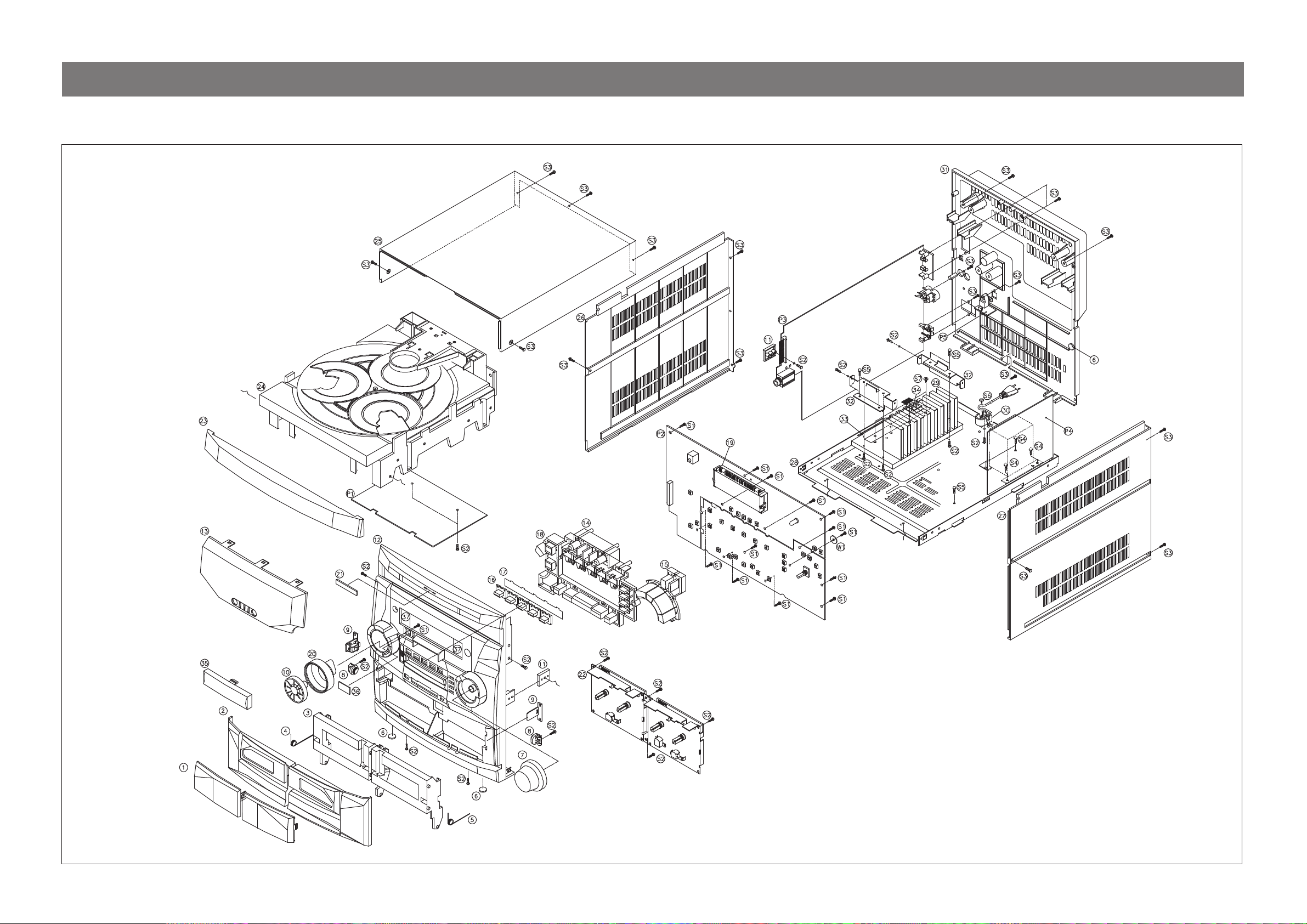
Exploded View and Mechanical Parts List
Model No:AMI-729L/R, 829L/R
— 5 —

Exploded View and Mechanical Parts List
Model No:AMI-729L/R, 829L/R
NO PARTS NAME CODE NO. DESCRIPTIONS Q’TY REMARKS
1 WINDOW DOOR A/B
2 DOOR COVER A/B
3 DOOR FRAME A/B
4 SPRING DOOR EJECT L 9CD30080L0 STS 1
5 SPRING DOOR EJECT R 9CD30080R0 STS 1
6 CUSHION FOOT 9CD4207700
7 KNOB VOLUME 9CD1337000 MIPS 1
DAMPER BASE «B»
8
DAMPER GEAR «B»
LOCKER BASE
9
LOCKER CAM
LOCKER SPRING
10 KNOB JOG DIAL 9CD1336800 MIPS 1
11 BRKT SIDE 9CD2412900 ABS 2
12 PANEL FRONT 9CD0308000 MIPS 1
13 WINDOW FLT 9CD1616700 ACRYL 1
14 KNOB CONTROL «A» 9CD13399A0 MIPS 1
15 KNOB CONTROL «B» 9CD13399B0 MIPS 1
16 KNOB FUNCTION 9CD1340000 ACRYL 1
17 PLATE FILTER 9CD0911200 LEXAN (T=0.125) 1
18 KNOB CONTROL «C» 9CD13399C0 MIPS 1
19 GUIDE FLT 9CD2506300 ABS 1
20 RING REFLECTOR 9CD3103700 ACRYL 1
21 BADGE BRAND ABS,STAMPING 1
22 CASS DECK MECHA 9CD6007800 S/S ADR 243AMW 1 AUTO REVERSE
23 DOOR CD 9CD1811400 MIPS 1
9CD16166A0
9CD16166B0
9CD18115A0
9CD18115B0
9CD1809400
9CD1809500
9CD2603300
9CD2603290
9CD0B01400
9CD0B01500
9CD0B01600
ACRYL
MIPS
MIPS
URETHAN FOAM RUBBER
ABS
ACETAL
ABS
ACETAL
PW-1
1
1
1
1
1
1
3
2
2
2
2
2
24 CD DECK MECHA
25 COVER TOP
26 COVER SIDE «L» 9CD0409200 MIPS 1
27 COVER SIDE «R» 9CD0409300 MIPS 1
28 CHASSIS BOTTOM 9CD0607100 SECC T1.0 1
29 HEAT SINK N50 9CD4405800 AL 7.0T 1 AMI-829L(50W)
30 HOLDER AC CORD 9CD2303300 ABS 1
9CD6007100
9CD6006900
9CD0409600
9CD0409100
CMS FR3 B TYPE
DCC-01B
MIPS 1
— 6 —
1
W/O HOLE
WITH HOLE
Exploded View and Mechanical Parts List
Model No:AMI-729L/R, 829L/R
NO PARTS NAME CODE NO. DESCRIPTIONS Q’TY REMARKS
31 COVER BACK 9CD0409813 MIPS 1
32 BRKT HEAT SINK 9CD2414600 SECC 1.0T 2 AMI-829L(50W)
33 BRKT HEAT SINK 9CD2414400 STS 1 AMI-829L(50W)
34 PLATE MICA «A» 9CD0910600 MICA 2
35 DECO MD DOOR 9CD1003100 MIPS 1
36 PLATE EON 9CD0911300 PVC 0.5T 1 DSP OPTION
S1 SCREW TAPTITE 7173261011 TT2 BIN 2.6X10 MFZN 12
S2 SCREW TAPTITE 7173301011 TT2 BIN 3X10 MFZN 15
S3 SCREW TAPTITE 7173301212 TT2 BIN 3X12 BK 25
S4 SCREW TAPTITE 7173400611 TT2 BIN 4X6 MFZN 8
S5 SCREW TAPTITE 7173300611 TT2 BIN 3X6 MFZN 5
S6 WASHER SCREW 9CD3102400 TT2 BIN 3X10+D14 1
S7 WASHER SCREW 9CD3102401 TT2 BIN 3X8+D10 4 AMI-829L(50W)
S8 SCREW TAPTITE 7173301412 TT2 BIN 3X14 BK 2 AMI-829L(50W)
P1 PCB CD 9CD6574800 197 X 123 X 1.6T 1
P2 PCB FRONT 9CD6580300 247 X 139 X 1.6T 1 AMI-829(50W)
P3 PCB MAIN 9CD6580500 319 X 197 X 1.6T 1 AMI-829(50W)
P4 PCB POWER 9CD6580600 106.5 X 88 X 1.6T 1 AMI-829(50W)
P5 PCD OPTICAL JACK 9CD6577800 29 X 21.5 X 1.6T 1
— 7 —
WIRING DIAGRAM
Model No:AMI-729L/R, 829L/R
SN:9738832101 7P 250MM
SN:9738833900 10P 350MM
CW900
P/T
30W
SN : 9738835000 3P 260MM
CW704
50W
SN : 9738804300 7P 350MM
CW703
10P CONN PINSN : 9736407800
SN : 9736407600 13P CONN PIN
SN : 9738833700 8P 220MM
FUNCTION
CN400
CN401
CW601
CW602
CW600
CW400
FD701
IC702
TUNER
CN900
CW508
SN:9738840900 19P 110MM
Pick-Up
CW503CW501
CN502
CW502
CN509
CW507
CN502 SN:9738824100 2P 400MM
SN:9738840800 16P 250MM
PLAY
HEAD
R/P HEAD
CW401
CW402
SN : 9738834000 11P 150MM
SN : 9738834100 13P 100MM
— 8 —
CW508
MM
CN703CN704CN701
MM
CD MECHA. ASS’Y
Loading…
Manuals Daewoo AMI-729L Files size: 7361 KB, Language: English, Format: pdf, Platform: Windows/Linux, Date: 2016-09-27
On this page you can download the manuals Daewoo AMI-729L. We suggest you familiarize yourself with the user management, service and repair instructions.
Here you will also find a list of ordering numbers for parts and components Daewoo AMI-729L.
All files are provided exclusively for introductory purposes. And they are not a repair guide, but are only aimed at helping you to familiarize yourself with the principle of building a device in more detail.
The contents of the guidelines presented here require you to know the technical English language.
If you are going to download service management manual Daewoo AMI-729L, In other words, the manual service, you are long to possess at least minimal knowledge in the field of electronics and understanding the basic principles of the operation of electromechanical devices.
To view the manuals, you will need Adobe Acrobat Reader version 9 and above or another program for viewing PDF files.
Due to the popularity of the information presented on the site and its free provision of the final user, a convincing request to use special software products for multi-threaded download downloads.
List of manuals for Daewoo AMI-729L
- Guide to use (User manual)
- Guide to service (Service manual)
- Guide to repair (Repair manual)
- The list of parts and components (PartList)
Инструкция музыкального центра Daewoo AMI-729L Размер: 7342 KB, Язык: Английский, Расширение: .pdf, Платформа: Adobe Acrobat, Дата: 2017-09-05
Руководство пользователя содержит основные технические характеристики устройства.
Комплект поставки может отличаться от описанного в руководстве.
Отдельная глава руководства пользователя посвящена условиям эксплуатации устройства. Описаны всевозможные варианты монтажа и установки.
Подробно описаны функции и особенности органов управления устройством.
Инструкция Daewoo AMI-729L предназначена для технически образованных людей и при детальном изучении гарантирует безопасную и долговременную работу устройства.
Руководство пользователя музыкального центра Daewoo AMI-729L содержит описание процедуры первоначальной настройки и подключения устройства и выполнение процедур сервисного обслуживания и подготовки расходных материалов.
Для изучения файла вам необходимо обладать хотя бы минимальным знанием английского языка, так как инструкция на русском для музыкального центра Daewoo AMI-729L пока еще не выпущена.
Описание специальных функций описано в отдельной главе инструкции.
Последняя глава руководства по эксплуатации содержит описание основных неисправностей музыкального центра и перечень основных действий по их устранению.
Пожалуйста используйте специальное программное обеспечение для скачивания файлов и по возможности дождитесь окончания загрузки первого файла перед началом загрузки второго.
Перечень основных разделов руководства пользователя музыкального центра Daewoo AMI-729L
- Технические характеристики
- Варианты монтажа
- Безопасность
- Органы управления
- Настройка устройства
- Стандартные функции
- Основные неисправности музыкального центра Daewoo AMI-729L
| Найти файл | |
|
|
|
| Найти DataSheet | |
| Сейчас на сайте | |
|
Онлайн всего: 371 Гостей: 319 Пользователей: 52 Level2, 152555, androidman, cobalagibro, Peter_Co, 0742476, cebanuradu2, unicom, rurra, AndreyF, voltamp, sergbam, Den0315, johnvi19, Alina1980, технал8888, VIKRYS, teleamatar, Vlad4305, Юра72, jayZeeR, CYB, SERGDG, tolik83, nokclub, greyfills, igor987, Smart123321, nv-muravjev, viktor333783, MiAlex1977, dve, Kors-79, мигал, bullic88, bnnapr1, ильшат, Владимир100, alexandrvarsha, iourik, dru161984, DIMMAS, MIXAIL22296, remont71, volgus, shamli, Serg9112, machenist, anna2288, [Полный список] |
|
| Приветствую Вас, Гость · RSS | 27.05.2025, 06:56:06 |
| В категории материалов: 49 Показано материалов: 1-49 |
Сортировать файлы в разделе Audio/DAEWOO по
Дате ·
Названию ·
Рейтингу ·
Комментариям ·
Загрузкам ·
Просмотрам
Страницы:
Servis Manual
PORTABLE STEREO CD RADIO CASSETTE RECORDER
Model: SP-701AG
Страницы:
Не тратьте время на поиск нужной запчасти, оформите заявку на заказ товара и наш менеджер свяжется с вами и согласует заказ.
Модель
Просьба указывать серийный номер техники, для ускорения
обработки заказа.
Запчасть
Если у вас есть Артикул (P/N) необходимой запчасти — укажите её.
Email используется для отправки уведомлений о ценах и наличии
Наша компания продает запчасти к бытовой технике уже много лет. Мы реализуем запчасти для музыкальных центров Daewoo в розницу и оптом в различные регионы России и Украины. С повсеместным распространением всемирной паутины все больше людей стали делать выбор в пользу интернет-магазинов, понимая, что торговля через интернет позволяет продавцу избежать затрат связанных с арендой помещения, содержания огромного штата продавцов и т.п. Поэтому, мы предлагаем покупателям запчасти для музыкальных центров по более низким ценам, нежели в обычных магазинах. Мы постоянно расширяем ассортимент запчастей, заключая договора напрямую с заводами-изготовителями.
Воспользовавшись услугами наших менеджеров, можно оперативно уточнить характеристики деталей для музыкальных центров Daewoo, получить консультацию по применению, взаимозаменяемости запчасти и другую дополнительную информацию.
Для оплаты заказа предусмотрены различные возможности, удобные как частным лицам, так и организациям. Доставка возможна несколькими способами: товар может доставить наш курьер, можно воспользоваться услугами транспортных компаний, либо осуществить пересылку почтой не только в такие крупные города как Москва, Санкт-Петербург, Нижний Новгород, Екатеринбург, Казань, Самара, Новосибирск, Киев, Днепропетровск, Донецк, Харьков, Запорожье, Одесса, Львов, а и в любой уголок России и Украины.