
Характеристики
|
Производитель |
|
|
Макс. измеряемая температура, °С |
800 |
|
Мин. измеряемая температура, °С |
-50 |
|
Точность, град |
±2 |
|
Принцип измерения |
инфракрасный |
|
Оптическое разрешение, (D:S) |
12:1 |
|
Коэффициент эмиссии |
0.1 |
|
Типоразмер элемента питания |
крона (6LR61;6F22;6KR61) |
Пирометр Condtrol Maxwell 4 3-16-044 и другие оригинальные товары в категории пирометры инфракрасные доступны на сайте интернет-магазина Бигам в Москве по специальной цене 4670 рублей. Перед покупкой данной модели бренда Condtrol рекомендуем посмотреть особенности, технические параметры, документацию и сертификаты на продукцию. Также предлагаем сравнить товар пирометр Condtrol Maxwell 4 3-16-044 с ассортиментом модификаций и аналогов из категории пирометры инфракрасные Condtrol.
-
-
Инструкция Condtrol Maxwell 4
Инструкция Condtrol Maxwell 4.pdf 1.31 МБ
На странице представлена инструкция по эксплуатации и другие материалы производителя о товаре пирометр Condtrol Maxwell 4 3-16-044, необходимые пользователю. Из руководства пользователя Condtrol (Кондтрол) можно узнать устройство изделия, срок службы и комплект поставки. Пирометр Condtrol Maxwell 4 3-16-044 и все товары серии требуют соблюдения правил использования, обслуживания, ухода и хранения.
-
Похожие товары
- June 3, 2024
- CONDTROL
Table of Contents
- CONDTROL Maxwell 4 Infrared Thermometer
- SAFETY REGULATIONS
- TECHNICAL SPECIFICATIONS
- PRODUCT DESCRIPTION
- Display
- Measuring unit
- OPERATION MODES
- Ultraviolet (UV) light mode
- OPTICAL RESOLUTION
- CARE AND MAINTENANCE
- WARRANTY
- Documents / Resources
- References
- Read User Manual Online (PDF format)
- Download This Manual (PDF format)
CONDTROL Maxwell 4 Infrared Thermometer

Congratulations on your purchase of infrared thermometer Maxwell4 CONDTROL.
Safety instructions given in this user manual should be carefully read before
you use the product for the first time.
SAFETY REGULATIONS
Attention! This user manual is an essential part of this product. The
user manual should be read carefully before you use the product for the first
time. If the product is given to someone for temporary use, be sure to enclose
a user manual to it.
- Do not misuse the product
- Do not remove warning signs and protect them from abrasion, because they contain information about the safe operation of the product.
- Laser radiation!
- Do not stare into the beam Class 2 laser
- < 1 mW 630-670nm EN60825-1: 2007-03
- Do not look into the laser beam or its reflection, with an unprotected eye or through an optical instrument. Do not point the laser beam at people or animals without the
- need. You can dazzle them.
- To protect your eyes close them or look aside.
- Do not let unauthorized people enter the zone of product operation.
- Store the product beyond reach of children and unauthorized people.
- It is prohibited to disassemble or repair the product yourself.
- Entrust product repair to qualified personnel and use original spare parts only.
- Do not use the product in explosive environment, close to flammable materials.
- Avoid heating the batteries to avoid the risk of explosion and electrolyte leakage. In case of liquid contact with skin, wash it immediately with soap and water. In case of contact with eyes, flush with clean water during 10 minutes and consult the doctor.
APPLICATION
Infrared thermometer Maxwell 4 CONDTROL is designed to measure object’s
surface temperature by non-contact method. It is equipped with temperature and
humidity sensors as well as an infrared sensor for object surface temperature
measurement, which can detect the «cold bridges» and places where dew point
can occur. Pull the trigger once to identify poorly insulated areas in windows
or to detect leakage areas in external walls. The function of ultraviolet
illumination allows carrying out diagnostics of air conditioning systems.
DELIVERY PACKAGE Infrared thermometer– 1pc. Power supply (9V 6F22) – 1 pc.
User manual – 1 pc.
TECHNICAL SPECIFICATIONS
| Measuring the range of object | -50 °С…800 °С |
|---|---|
| temperature | -58 °F…1472 °F |
Accuracy of surface
| -50°C…0°C /
-58°F…32°F:
| ±3 °С
temperature| |
measurement| 0°C…800°C /| ±2.0% or ±2°C
| 32°F…1472°F:|
Measuring the range of ambient temperature|
-10 °C…60 °C / 14 °F…140 °F
| -10 °C…0 °C| ±1.5 °C/3 °F
| (14 °F…32 °F):|
Accuracy of ambient| 0 °C…40°C| ±1.0 °C/2 °F
temperature measurement| (32 °F…113 °F):|
| 40 °C…60°C| ±1.5 °C/3 °F
| (113 °F…140 °F):|
Measuring the range of relative humidity|
0% …100%
| 0%…20%:| ±5.0%
Accuracy of relative
humidity measurement
| 20%…80%:| ±4.0%
| 80%…100%:| ±5.0%
Measuring the range of dew point|
-10°C…50°C / 14°F…122°F
Accuracy of dew point measurement|
±1.5°C / 3°F
Optical resolution| 12:1
Response time| <0.5 sec
Automatic shutdown| 30 sec
Spectral sensitivity| 8…14 µm
Emissivity| 0.1…1.0 adjustable
Working temperature| 0°С …40°С
Storage temperature| -10°С…60°С
Relative humidity
| 10…95% for operation
< 80% for storage
Power supply| 1 x 9V 6F22
Laser| Class II, 630-670 nm, <1 mW
Dimensions| 104x164x47 mm
Weight| 155 g
PRODUCT DESCRIPTION
- LED indicator
- Display
- Activate/deactivate the laser point/adjust emissivity (decrease value)
- Select the operation mode
- Switch on/off ultraviolet light/ adjust emissivity (increase value)
- Laser point exit window
- Ultraviolet light exit window
- Infrared sensor
- Trigger
- Battery cover
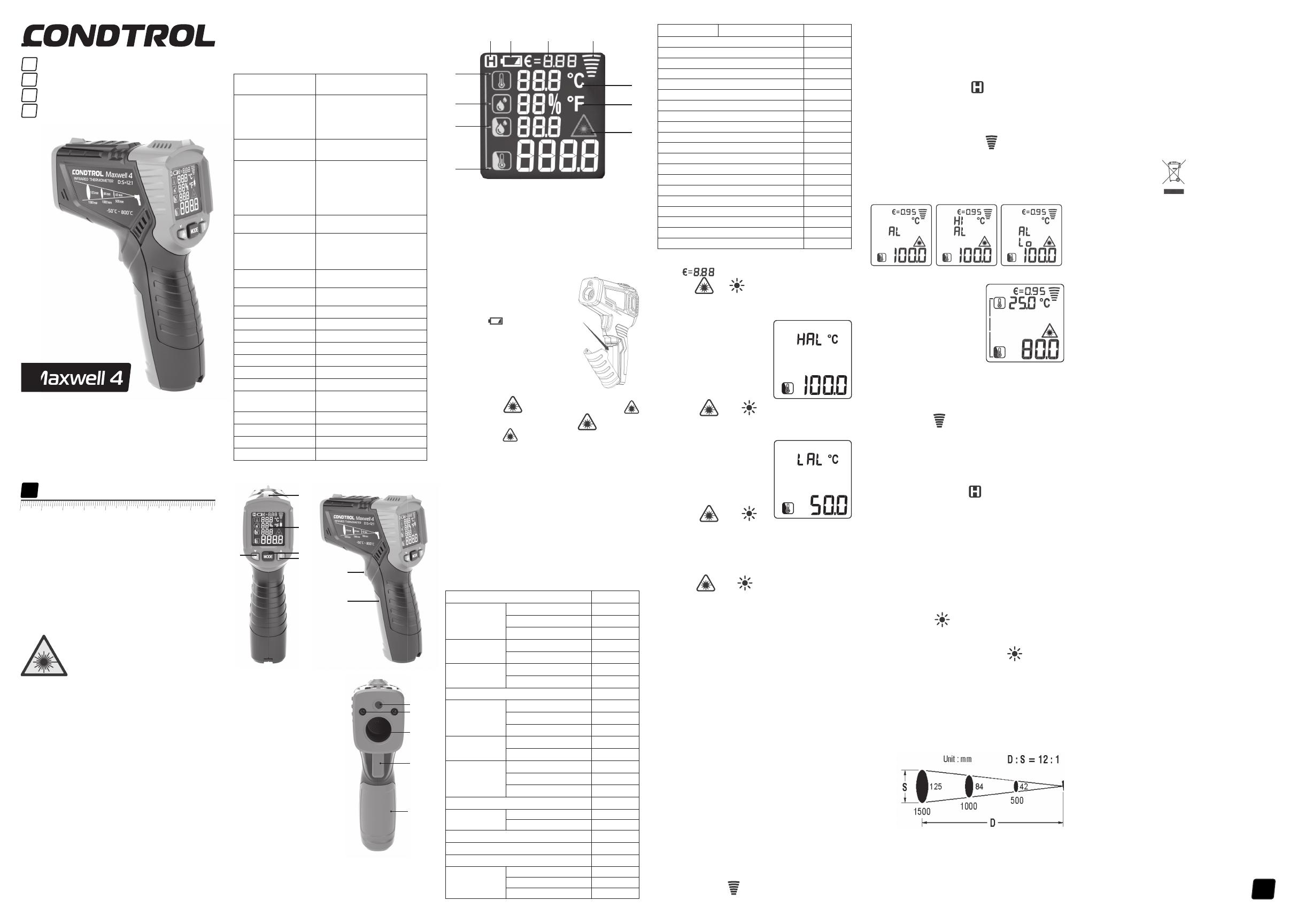
Display
- Ambient temperature value
- Relative humidity value
- Dew point temperature value
- Surface temperature value
- Indication of activated laser point
- Temperature measurement unit – Fahrenheit
- Temperature measurement unit – Celsius
- Indication of active measurement
- Emissivity value
- Power indicator
- Indication of data hold on the display
INSTALL/REPLACE THE BATTERY
Open the battery cover. Install the battery observing correct polarity. Put
the battery cover back and push it until a click is heard.
If the symbol of low battery appears on the display, replace the battery.
Switch on/off
Short pull the trigger to switch the device on. The device is ready to work.
The device switches off automatically in 30 seconds after the last press of
any button.
SETTINGS
- Laser point
Short press the button, to activate laser point. A symbol will appear on the
display. Short press the button, to deactivate the laser point. A symbol will
disappear from the display. Laser point is only used for aiming and can be
switched off when working at a short distance to save battery power.
Laser pointer is on as long as the trigger is pulled.
Emissivity
All objects emit thermal energy. The volume of radiated energy depends on the
surface temperature and emissivity of the object. The IR thermometer measures
the intensity of radiation and uses it to calculate the temperature of the
object. Objects with different surfaces but equal temperatures emit different
amounts of thermal energy. Most of the objects and materials, for example,
painted metals, wood, water, leather, and fabric have high emissivity (0.9 and
more) and emit more energy than shiny surfaces and unpainted metals with an
emissivity less than 0.6. Adjustment of emissivity allows the device to take
it into account and minimize measurement error.
Table 1. Emissivity of materials
| Measured surface | radiation |
|---|---|
| Aluminum | Oxidized |
| A3003 alloy (oxidized) | 0.3 |
| A3003 alloy (coarse) | 0.1~0.3 |
| Brass | Polished |
| Oxidized | 0.5 |
| Copper | Oxidized |
| Electronic terminal board | 0.6 |
| Hastelloy | 0.3~0.8 |
| Ferro-nickel | Oxidized |
| Abrasive blasting | 0.3~0.6 |
| Electropolishing | 0.15 |
| Iron | Oxidized |
| Rust | 0.5~0.7 |
| Iron (casting) | Oxidized |
| Unoxidized | 0.2 |
| Fusion cast | 0.2~0.3 |
| Iron (casting) passivation | 0.9 |
| Lead | Rough |
| Oxidized | 0.2~0.6 |
| Molybdenum oxidation | 0.2~0.6 |
| Nickel oxidation | 0.2~0.5 |
| Platinum black | 0.9 |
| Steel | Cold rolling |
| Grinding steel plate | 0.4~0.6 |
| Polished steel plate | 0.1 |
| Zinc | Oxidized |
| — | — |
| Asbestos | 0.95 |
| Asphalt | 0.95 |
| Basalt | 0.7 |
| Carbon (unoxidized) | 0.8~0.9 |
| Graphite | 0.7~0.8 |
| Silicon carbide | 0.9 |
| Ceramics | 0.95 |
| Clay | 0.95 |
| Concrete | 0.95 |
| Cloth | 0.95 |
| Glass plate | 0.85 |
| Gravel | 0.95 |
| Plaster | 0.8~0.95 |
| Ice | 0.98 |
| Limestone | 0.98 |
| Paper | 0.95 |
| Plastics | 0.95 |
| Soil | 0.9~0.98 |
| Water | 0.93 |
| Timber | 0.9~0.95 |
- Press and hold MODE for 2 seconds to enter the menu of settings. The symbol will appear on the display. Use buttons to adjust the emissivity value. To exit, the menu of settings pull the trigger or press and hold MODE for 2 seconds.
- Setting of the measuring range High alarm Press and hold MODE for 2 seconds to enter the menu of settings. Short press MODE 1 time to select the setting of the upper-temperature limit. Symbol HAL will appear on the display.
- Use buttons to adjust the value of the upper-temperature limit. To exit, the menu of settings pull the trigger or press and hold MODE for 2 seconds. Low alarm
- Press and hold MODE for 2 seconds to enter the menu of settings. Press and hold MODE 2 times to select the setting of the bottom temperature limit. Symbol LAL will appear on the display.
- Use buttons to adjust the value of the bottom temperature limit. To exit, the menu of settings pull the trigger or press and hold MODE for 2 seconds.
Measuring unit
Press and hold MODE for 2 seconds to enter the menu of settings. Press the
button mode 3 times. Symbol 0C will appear on the display.
Use buttons to select the measuring unit (°C – degrees Celsius / °F –
Fahrenheit degree). To exit, the menu of settings pull the trigger or press
and hold mode for 2 seconds.
OPERATION MODES
- Dew point mode
The Dew point indicates the temperature at which the water vapor contained in
the air starts to condense. The Dew point depends on relative humidity and
ambient temperature. If the surface temperature is below the dew point, then
water begins to condense on this surface. The greater the difference between
both temperatures and the higher the relative humidity, the stronger the
condensation. The condensate water formed on the surface is the main cause of
mold formation. In the dew point mode, ambient temperature and relative
humidity of the air are measured. Based on these two values, the temperature
of the dew point is calculated. In addition, the surface temperature is
measured. The dew point is compared with the surface temperature, and the
result allows us to estimate the probability of mold formation. The dew point
is compared with the surface temperature and the result allows us to estimate
the probability of mold formation. The Dew point indicates the temperature at
which the water vapor contained in the air starts to condense. The Dew point
depends on relative humidity and ambient temperature. If the surface
temperature is below the dew point, then water begins to condense on this
surface. The greater the difference between both temperatures and the higher
the relative humidity, the stronger the condensation. The condensate water
formed on the surface is the main cause of mold formation. In the dew point
mode, ambient temperature and relative humidity of the air are measured. Based
on these 2 values, the temperature of the dew point is calculated. In
addition, the surface temperature is measured. The dew point is compared with
the surface temperature, and the result allows to estimate the probability of
mold formation. Switch on the device. Aim the device at the object of
measurement and pull the trigger. Keep the trigger pulled to enter continuous
measurement. The symbol of active measurement will appear on the display.
Measurement results will appear on the display in real
time mode.
If the LED indicator is green during the measurement, there is no risk of
mold. If the indicator light is yellow during the measurement, there is a
possibility of mold appearance. If the indicator light is red during the
measurement, there is a high risk of mold appearance. When the trigger is
released, the device keeps the last measured values on the display. The symbol
appears on the display. 2) Out of the temperature range In this mode the
device measures surface temperature only. Switch on the device. Press MODE 1
time. Aim the device at the object of measurement and pull the trigger. Keep
the trigger pulled to enter continuous measurement. Symbols of active
measurement will appear on the display. Measurement results will appear on the
display in real-time mode. If the surface temperature exceeds the upper-
temperature limit, a symbol Hi will appear on the display. If the surface
temperature is below the bottom temperature limit, a symbol Lo will appear on
the display.

Thermal bridge mode
A thermal bridge is a localized area in the thermal insulation of buildings
where intensive heat transfer from the warmer side to the colder side occurs.
The existence of thermal bridges causes increased heat loss. The lower
temperature of the internal surface in the area of the thermal bridge compared
to the surface temperature of undamaged areas causes the risk of condensation
and, as a result, mold formation. Switch on the device. Short press button
MODE 2 times to select thermal bridge mode. Aim the device at the object of
measurement and pull the trigger. Keep the trigger pulled to enter continuous
measurement. Symbols of active measurement will appear on the display.
Measurement
results will appear on the display in real-time mode. If there is no thermal
bridge in the area of measurement, the LED indicator turns green. If there may
be a thermal bridge in the area of measurement, the LED indicator turns
yellow. If there is a thermal bridge in the area of measurement, the LED
indicator turns red, which is evidence of poor insulation. When the trigger is
released, the device keeps the last measured values on the display. The symbol
appears on the display.
Ultraviolet (UV) light mode
IR-thermometer Maxwell 4 has the function of ultraviolet illumination, which
allows you to diagnose the air conditioning system of the car for refrigerant
leaks. The main advantage of this method is the maximum simplicity of
diagnostics. It is based on the use of a paint, which is mixed with freon and
pumped into the air conditioning system. Before starting the diagnostics, it
is necessary to perform a full refueling of the system. After refueling, the
air conditioning system can be used at full capacity. In case of air
conditioning system performance deterioration diagnostics should be carried
out, it is highly recommended to perform diagnostics in a dark room to obtain
the most accurate result. Start the engine and switch on the air conditioner.
Switch on the device. Short press to switch on UV light and examine all
components of the air conditioning system. The places where refrigerant leak
occurs can easily be seen. They will glow with yellow-green color. As soon as
diagnostics is finished, short press to switch off the UV light.
OPTICAL RESOLUTION
As the distance from the device to the object increases, the size of the
measured spot on the object’s surface increases as well. To determine the size
of the spot (S) you need to divide the distance from the device to the target
(D) by 12. Laser points serve as the reference to determine the size and
position of the measured spot.
125 84 42 – spot (S)
1500 1000 500 – distance (D)

CARE AND MAINTENANCE
-
Attention! The product is an accurate optical mechanic device and requires careful handling. Maintenance of the following recommendations will extend the life of the device:
Keep the product clean and protected from any bumps, dust, and dampness; do
not allow getting moisture, dust or other dirt inside of the product. -
Do not expose the product to extreme temperatures.
-
If liquids get inside the product first remove the batteries, then contact a service center
-
Do not store or use the product under high humidity conditions for a long time.
-
Clean the product with soft wet cloth.
Keep the device optics clean and protect it from mechanical impact. -
Failure to observe the following rules may result in leakage of electrolyte from the batteries and damage the device:
-
Remove the battery from the product if you do not use it for a long time.
-
Do not leave discharged battery in the device.
Do not heat the battery. -
UTILIZATION
Expired tools, accessories and package should be passed for waste recycle.
Please send the product to the following address for proper recycle: -
CONDTROL GmbH
-
Wasserburger Strasse 9
-
84427 Sankt Wolfgang
-
Germany
-
Do not throw the product in municipal waste! According to European directive 2002/96/ЕC expired measuring tools and their components must be collected separately and submitted to environmentally friendly recycle of wastes.
WARRANTY
All CONDTROL GmbH products go through post-production control and are governed
by the following warranty terms. The buyer’s right to claim about defects and
general provisions of the current legislation do not expire.
- CONDTROL GmbH agrees to eliminate all defects in the product, discovered while warranty period, that represent the defect in material or workmanship in full volume and at its own expense.
- The warranty period is 24 months and starts from the date of purchase by the end customer (see the original supporting document).
- The warranty doesn’t cover defects resulting from wear and tear or improper use, malfunction of the product caused by failure to observe the instructions of this user manual, untimely maintenance and service and insufficient care, the use of non-original accessories and spare parts. Modifications in design of the product relieve the seller from responsibility for warranty works. The warranty does not cover cosmetic damage, that doesn’t hinder normal operation of the product.
- CONDTROL GmbH reserves the right to decide on replacement or repair of the device.
- Other claims not mentioned above, are not covered by the warranty.
- After holding warranty works by CONDTROL GmbH warranty period is not renewed or extended.
- CONDTROL GmbH is not liable for loss of profit or inconvenience associated with a defect of the device, rental cost of alternative equipment for the period of repair.
This warranty applies to German law except provision of the United Nations
Convention on contracts for the international sale of goods (CISG).
In warranty case please return the product to retail seller or send it with
description of defect to the following address:
- CONDTROL GmbH
- Wasserburger Strasse 9
- 84427 Sankt Wolfgang
- Germany
Documents / Resources
|
CONDTROL Maxwell 4 Infrared
Thermometer
[pdf] User Manual
Maxwell 4 Infrared Thermometer, Maxwell 4, Infrared Thermometer, Thermometer
—|—
References
- Интернет магазин производителя лазерных измерительных приборов Condtrol
Read User Manual Online (PDF format)
Read User Manual Online (PDF format) >>
Download This Manual (PDF format)
Download this manual >>
- Описание
- Как купить
- Оплата
- Доставка
-
Видео
- Отзывы
- Задать вопрос
Описание
Пирометр Condtrol Maxwell 4 3-16-044 — бесконтактный инфракрасный пирометр c лазерным целеуказателем. С его помощью происходит мониторинг тепловых потерь, поиск мостиков холода, зон потери тепла, засоров в системе теплоснабжения, перегрева подвижных деталей в автомобиле или в других механизмах.
Инфракрасный пирометр пригодится как профессионалам, работающим на производстве или в сфере ЖКХ, так и любителям для бытового использования.
Особенности:
Бесконтактный пирометр очень удобен в работе, поскольку он хорошо лежит в руке и имеет небольшой вес (155 грамм). Кроме этого, все элементы управления расположены эргономично и удобно, а нескользящая рельефная ручка уменьшает риск случайного падения.
Использование целеуказателя позволяет произвести точное наведение ИК-пирометра на небольшие детали или участки поверхности.
Время отклика — 500 мс., т.е. температура поверхности определяется почти мгновенно и позволяет экономить время при проведении множественных замеров.
Пирометр оснащен подсветкой дисплея, позволяющей работать при разных вариантах освещения. Кроме того, подсветка не обладает избыточной яркостью и не утомляет глаза.
Рабочий диапазон измерения температуры поверхности: от -50°C до +800°C (от -58F до +1472F)
Погрешность измерения температуры поверхности:
1) от -50 до 0 градусов Цельсия (от -58F до +32F) — +- 3 градуса Цельсия
2) от 0 до 800 градусов Цельсия (от 32F до +1472F) — +2% или -+ 2 градуса Цельсия
Диапазон измерений температуры окружающей среды от -10°C до +60°C (от -14F до +140F)
Погрешность измерений температуры окружающей среды +- 1 градус Цельсия
Диапазон измерений относительной влажности от 0% до 99%
Погрешность измерения относительной влажности +- 5%
Диапазон измерения точки росы от -10°C до +50°C (от -14F до +140F)
Погрешность определения температуры точки росы +- 1 градус Цельсия
Оптическое разрешение 12:1
Время отклика <0.5 секунд
Автоматическое выключение прибора 30 секунд
Спектральный диапазон 8 … 14 мкм
Коэффициент излучения 0.1 … 1.0, регулируемый
Температура эксплуатации от 0 до 40 градусов Цельсия
Температура хранения от -10 до + 60 градусов Цельсия
Допустимая относительная влажность 10 … 95% — рабочий режим, 80% — хранение
Элементы питания 1 x 9В 6F22
Тип лазера Класс лазера II, 630-670 нм, < 1 мВт
Яркий ЖК-дисплей с подсветкой и четким шрифтом.
Автоотключение для экономии заряда элементов питания.
Подстройка коэффициента излучения под разные поверхности.
Габариты 104 x 164 x 47 мм
Вес устройства — 155 г.
Преимущества Condtrol Maxwell 4 3-16-044:
Простота использования — надо просто навести лазерный указатель на объект, нажать на триггер, а результат измерения высветится на экране.
Безопасность мониторинга температуры — пирометр имеет оптическое разрешение 12:1, благодаря чему способен производить измерение температуры на расстоянии от объекта, например, горячего или находящегося под напряжением.
Удобство использования — измерения отображаются большими цифрами, которые легко считываются, на дисплее, а, в случае плохой видимости, выручит подсветка экрана.
Пирометр имеет круговой прицел, который позволяет пользователю наглядно увидеть зону измерения и избежать ошибок при выборе расстояния для измерения.
Пирометр позволяет мониторить критические зоны — в случае, если температура выйдет за пределы установленного параметра сработает сигнализация, и, тем самым, позволит в кратчайшие сроки определить перегрев деталей конструкции, а также, отклонения температуры поверхности труднодоступных объектов таких, как распределительные щиты, системы кондиционирования или котлы.
Инфракрасный пирометр обеспечивает минимальную погрешность измерения — это достигается благодаря возможности настройки коэффициента теплового излучения под ваши цели и задачи.
Данный пирометр имеет встроенный гигрометр, с помощью которого можно измерить температуру среды и влажность воздуха.
Документы
Как купить
Оформить заказ на нашем сайте легко. Просто добавьте выбранные товары в корзину, а затем перейдите на страницу Корзина, проверьте правильность заказанных позиций и нажмите кнопку «Оформить заказ» или «Быстрый заказ».
Быстрый заказ
Функция «Быстрый заказ» позволяет покупателю не проходить всю процедуру оформления заказа самостоятельно. Вы заполняете форму, и через короткое время вам перезвонит менеджер магазина. Он уточнит все условия заказа, ответит на вопросы, касающиеся качества товара, его особенностей. А также подскажет о вариантах оплаты и доставки.
По результатам звонка, пользователь либо, получив уточнения, самостоятельно оформляет заказ, укомплектовав его необходимыми позициями, либо соглашается на оформление в том виде, в котором есть сейчас. Получает подтверждение на почту или на мобильный телефон и ждёт доставки.
Оформление заказа в стандартном режиме
Если вы уверены в выборе, то можете самостоятельно оформить заказ, заполнив по этапам всю форму.
Заполнение адреса
Выберите из списка название вашего региона и населённого пункта. Если вы не нашли свой населённый пункт в списке, выберите значение «Другое местоположение» и впишите название своего населённого пункта в графу «Город». Введите правильный индекс.
Доставка
В зависимости от места жительства вам предложат варианты доставки. Выберите любой удобный способ.
Оплата
Выберите оптимальный способ оплаты.
Покупатель
Введите данные о себе: ФИО, адрес доставки, номер телефона. В поле «Комментарии к заказу» введите сведения, которые могут пригодиться курьеру, например: подъезды в доме считаются справа налево.
Оформление заказа
Проверьте правильность ввода информации: позиции заказа, выбор местоположения, данные о покупателе. Нажмите кнопку «Оформить заказ».
Наш сервис запоминает данные о пользователе, информацию о заказе и в следующий раз предложит вам повторить к вводу данные предыдущего заказа. Если условия вам не подходят, выбирайте другие варианты.
Оплата
Вы можете выбрать один из трех вариантов оплаты:
Оплата наличными
При выборе варианта оплаты наличными, вы дожидаетесь приезда курьера и передаёте ему сумму за товар в рублях. Курьер предоставляет товар, который можно осмотреть на предмет повреждений, соответствие указанным условиям. Покупатель вносит денежные средства и получает чек.
Безналичный расчёт
При оформлении заказа в корзине вы можете выбрать вариант безналичной оплаты. Это, прежде всего, касается юридических лиц! После оформления заказа менеджер свяжется с вами для уточнения ваших контактов и запроса ваших реквизитов. Для ускорения процесса выставления счета вы можете сами отправить карточку вашего предприятия на нашу почту zakaz@instrumenty-dlya-doma.ru. В теме письма укажите, пожалуйста, номер заказа, для которого необходимо выставить счет.
Предоплата за товар на расчетный счет
Если вы находитесь не в Челябинске, то отправка товара будет производиться только по предоплате. Менеджер выставит вам счет, в котором будут реквизиты, на которые надо будет оплатить товар.
Доставка
Наш интернет-магазин предлагает несколько вариантов доставки:
- курьерская служба нашего магазина (только для жителей города Челябинск);
- курьерская служба транспортных компаний (ЛУЧ, GTD, CDEK и другие);
- терминалы транспортных компаний (ЛУЧ, GTD, CDEK и другие) (для жителей любого города РФ);
- почтовая доставка;
Курьерская доставка*
Вы можете заказать доставку товара с помощью курьера, который прибудет по указанному адресу в будние дни после 18.00, в субботу и воскресенье с 9.00 до 21.00. Курьерская служба, после поступления товара на склад, свяжется с вами и предложит выбрать удобное время доставки. Уточнит адрес.
Вы вскрываете упаковку при курьере, осматриваете на целостность и соответствие указанной комплектации.
Стоимость доставки уточняйте у менеджера интернет-магазина. Оплата производится курьеру только наличными!
Курьерская доставка транспортных компаний
Уточнить сроки и время доставки вы можете на сайте транспортной компании или у нашего менеджера по телефону. Курьерская служба, после поступления товара на склад, свяжется с вами и предложит выбрать удобное время доставки. Уточнит адрес.
Вы вскрываете упаковку при курьере, осматриваете на целостность и соответствие указанной комплектации.
Обратите внимание, курьерская доставка транспортных компаний оплачивается отдельно!
*Действует ли в вашем городе курьерская служба, уточняйте у менеджера магазина.
Терминалы транспортных компаний
Отправка возможна в любой город РФ любой транспортной компанией, представленной в городе Челябинск, по полной (100%) предоплате — подробности уточняйте у менеджера интернет-магазина.
Доставка до терминала транспортной компании в Челябинске производится БЕСПЛАТНО нашим курьером.
Почтовая доставка
Если в вашем городе не действует курьерская служба, то вы можете заказать доставку через почту России. Сразу по прибытии товара, на ваш адрес придет извещение о посылке.
Перед оплатой вы можете оценить состояние коробки (не вскрывая): вес, целостность. Если вам кажется, что заказ не соответствует параметрам или коробка повреждена, попросите сотрудника почты составить акт о вскрытии. Вскрывать коробку самостоятельно вы можете только после того, как оплатили заказ.
Срок доставки
В зависимости от вашего региона проживания, доставка занимает разное время.
Обратите внимание, что сроки носят ориентировочный характер, более точные сроки вы можете уточнить на сайтах транспортных компаний и у менеджера интернет-магазина!
|
Регион |
Курьерская доставка |
Курьерская доставка ТК |
Терминалы ТК |
Почта России |
|
Челябинск и пригород |
2-3 рабочих дня |
|||
|
Челябинская область |
2-3 рабочих дня |
до 5 дней |
||
|
Урал и Поволжье |
2-5 рабочих дней |
2-5 рабочих дней |
до 14 дней |
|
|
Сибирь |
до 12 рабочих дней |
до 12 рабочих дней |
14-21 день |
О доставке в другие регионы России и страны СНГ уточняйте у менеджеров магазина.
Видео
Задать вопрос
Вы можете задать любой интересующий вас вопрос по товару или работе магазина.
Наши квалифицированные специалисты обязательно вам помогут.
Задать вопрос
1
— If liquids get inside the product first remove the batteries, then
contact a service center
— Do not store or use the product under high humidity conditions for
a long time.
— Clean the product with soft wet cloth.
— Keep the device optics clean and protect it from mechanical impact.
Failure to observe the following rules may result in leakage of
electrolyte from the batteries and damage the device:
— Remove the battery from the product if you do not use it for a long
time.
— Do not leave discharged battery in the device.
— Do not heat the battery.
UTILIZATION
Expired tools, accessories and package should be passed for waste
recycle. Please send the product to the following address for proper
recycle:
CONDTROL GmbH
Wasserburger Strasse 9
84427 Sankt Wolfgang
Germany
Do not throw the product in municipal waste!
According to European directive 2002/96/ЕC expired measuring tools
and their components must be collected separately and submitted to
environmentally friendly recycle of wastes.
WARRANTY
All CONDTROL GmbH products go through post-production control
and are governed by the following warranty terms. The buyer’s
right to claim about defects and general provisions of the current
legislation do not expire.
1) CONDTROL GmbH agrees to eliminate all defects in the product,
discovered while warranty period, that represent the defect in
material or workmanship in full volume and at its own expense.
2) The warranty period is 24 months and starts from the date
of purchase by the end customer (see the original supporting
document).
3) The warranty doesn’t cover defects resulting from wear and tear
or improper use, malfunction of the product caused by failure to
observe the instructions of this user manual, untimely maintenance
and service and insufficient care, the use of non-original accessories
and spare parts. Modifications in design of the product relieve the
seller from responsibility for warranty works. The warranty does not
cover cosmetic damage, that doesn’t hinder normal operation of the
product.
4) CONDTROL GmbH reserves the right to decide on replacement or
repair of the device.
5) Other claims not mentioned above, are not covered by the warranty.
6) After holding warranty works by CONDTROL GmbH warranty period is
not renewed or extended.
7) CONDTROL GmbH is not liable for loss of profit or inconvenience
associated with a defect of the device, rental cost of alternative
equipment for the period of repair.
This warranty applies to German law except provision of the United
Nations Convention on contracts for the international sale of goods
(CISG).
In warranty case please return the product to retail seller or send it with
description of defect to the following address:
CONDTROL GmbH
Wasserburger Strasse 9
84427 Sankt Wolfgang
Germany
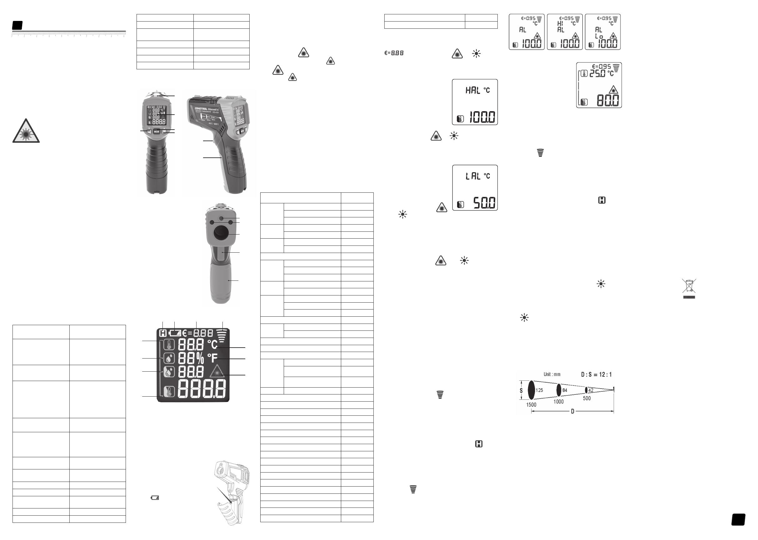
1 – Ambient temperature value
2 – Relative humidity value
3 – Dew point temperature value
4 – Surface temperature value
5 – Indication of activated laser point
6 – Temperature measurement unit – Fahrenheit
7 – Temperature measurement unit – Celsius
8 – Indication of active measurement
9 – Emissivity value
10 – Power indicator
11 – Indication of data hold on the display
INSTALL/REPLACE THE BATTERY
Open the battery cover. Install the battery
observing correct polarity. Put the battery
cover back and push it until a click is heard.
If the symbol of low battery appears
on the display, replace the battery.
Switch on/off
Short pull the trigger to switch the device on.
The device is ready to work.
The device switches off automatically in 30
seconds after the last press on any button.
SETTINGS
1) Laser point
Short press button , to activate laser point*. Symbol
will appear on the display. Short press button , to deactivate
laser point. Symbol will disappear from the display. Laser point
is only used for aiming and can be switched off when working at short
distance to save battery power.
*Laser pointer is on as long as the trigger is pulled.
2) Emissivity
All objects emit thermal energy. The volume of radiated energy
depends on the surface temperature and emissivity of the object.
The IR-thermometer measures the intensity of radiation and uses
it to calculate the temperature of the object. Objects with different
surfaces but equal temperature emit different amount of thermal
energy. Most of the objects and materials, for example, painted
metals, wood, water, leather, fabric have a high emissivity (0.9 and
more) and emit more energy than shiny surfaces and unpainted
metals with emissivity less than 0.6. Adjustment of emissivity allows
the device to take it into account and to minimize the measurement
error.
Table 1. Emissivity of materials
Measured surface radiation
Aluminum Oxidized 0.2~0.4
A3003 alloy (oxidized) 0.3
A3003 alloy (coarse) 0.1~0.3
Brass Polished 0.3
Oxidized 0.5
Copper Oxidized 0.4~0.8
Electronic terminal board 0.6
Hastelloy 0.3~0.8
Ferro-nickel Oxidized 0.7~0.95
Abrasive blasting 0.3~0.6
Electropolishing 0.15
Iron Oxidized 0.5~0.9
Rust 0.5~0.7
Iron (casting) Oxidized 0.6~0.95
Unoxidized 0.2
Fusion cast 0.2~0.3
Iron (casting) passivation 0.9
Lead Rough 0.4
Oxidized 0.2~0.6
Molybdenum oxidation 0.2~0.6
Nickel oxidation 0.2~0.5
Platinum black 0.9
Steel Cold rolling 0.7~0.9
Grinding steel plate 0.4~0.6
Polished steel plate 0.1
Maxwell 4
User manual
Infrared thermometer
EN
Congratulations on your purchase of infrared thermometer
Maxwell4 CONDTROL.
Safety instructions given in this user manual should be carefully read
before you use the product for the first time.
SAFETY REGULATIONS
Attention! This user manual is an essential part of this product.
The user manual should be read carefully before you use the product
for the first time. If the product is given to someone for temporary
use, be sure to enclose user manual to it.
— Do not misuse the product
— Do not remove warning signs and protect them from abrasion,
because they contain information about safe operation of the
product.
Laser radiation!
Do not stare into beam
Class 2 laser
<1 mW 630-670nm
EN60825-1: 2007-03
— Do not look into the laser beam or its reflection, with unprotected
eye or through an optical instrument. Do not point the laser beam at
people or animals without the need. You can dazzle them.
— To protect your eyes close them or look aside.
— Do not let unauthorized people enter the zone of product operation.
— Store the product beyond reach of children and unauthorized
people.
— It is prohibited to disassemble or repair the product yourself.
Entrust product repair to qualified personnel and use original spare
parts only.
— Do not use the product in explosive environment, close to
flammable materials.
— Avoid heating the batteries to avoid the risk of explosion and
electrolyte leakage. In case of liquid contact with skin, wash it
immediately with soap and water. In case of contact with eyes, flush
with clean water during 10 minutes and consult the doctor.
APPLICATION
Infrared thermometer Maxwell 4 CONDTROL is designed to measure
object’s surface temperature by non-contact method. It is equipped
with temperature and humidity sensors as well as an infrared sensor
for object surface temperature measurement, which can detect
the «cold bridges» and places where dew point can occur. Pull the
trigger once to identify poorly insulated areas in windows or to
detect leakage areas in external walls. The function of ultraviolet
illumination allows carrying out diagnostics of air conditioning
systems.
Maxwell 4
DELIVERY PACKAGE
Infrared thermometer– 1pc.
Power supply (9V 6F22) — 1 pc.
User manual — 1 pc.
TECHNICAL SPECIFICATIONS
Measuring range of object
temperature
-50 °С…800 °С
-58 °F…1472 °F
Accuracy of surface
temperature
-50°C…0°C /
-58°F…32°F:
0°C…800°C /
32°F…1472°F:
±3 °С
±2.0% or ±2°C
measurement
Measuring range of
ambient temperature -10 °C…60 °C / 14 °F…140 °F
Accuracy of ambient
temperature measurement
-10 °C…0 °C
(14 °F…32 °F):
±1.5 °C/3 °F
0 °C…40°C
(32 °F…113 °F):
±1.0 °C/2 °F
40 °C…60°C
(113 °F…140 °F):
±1.5 °C/3 °F
Measuring range of
relative humidity 0% …100%
Accuracy of relative
humidity measurement
0%…20%: ±5.0%
20%…80%: ±4.0%
80%…100%: ±5.0%
Measuring range of dew
point -10°C…50°C / 14°F…122°F
Accuracy of dew point
measurement ±1.5°C / 3°F
Optical resolution 12:1
Response time <0.5 sec
Automatic shutdown 30 sec
Spectral sensitivity 8...14 µm
Emissivity 0.1…1.0 adjustable
Working temperature 0°С …40°С
Storage temperature —10°С…60°С
Relative humidity 10…95% for operation
< 80% for storage
Power supply 1 x 9V 6F22
Laser Class II, 630—670 nm, <1 mW
Dimensions 104x164×47 mm
Weight 155 g
PRODUCT DESCRIPTION
Infrared thermometer
EN
Infrarot—Pyrometer
DE
EN User manual 1
DE Bedienungsanleitung 2
PL Instrukcja obsługi 3
R U Р у ко в о д с т в о п о э к с п л у а т а ц и и 4
Zinc Oxidized 0.1
Asbestos 0.95
Asphalt 0.95
Basalt 0.7
Carbon (unoxidized) 0.8~0.9
Graphite 0.7~0.8
Silicon carbide 0.9
Ceramics 0.95
Clay 0.95
Concrete 0.95
Cloth 0.95
Glass plate 0.85
Gravel 0.95
Plaster 0.8~0.95
Ice 0.98
Limestone 0.98
Paper 0.95
Plastics 0.95
Soil 0.9~0.98
Water 0.93
Timber 0.9~0.95
Press and hold MODE for 2 seconds to enter the menu of settings.
Symbol will appear on the display.
Use buttons and to adjust the emissivity value. To exit
the menu of settings pull the trigger or press and hold MODE for
2 seconds.
3) Setting of the measuring range
High alarm
Press and hold MODE during
2 seconds to enter the menu of
settings. Short press MODE 1 time
to select the setting of the upper
temperature limit. Symbol HAL will
appear on the display.
Use buttons and to adjust the value of the upper
temperature limit. To exit the menu of settings pull the trigger or
press and hold MODE during 2 seconds.
Low alarm
Press and hold MODE during
2 seconds to enter the menu of
settings. Press and hold MODE 2
times to select the setting of the
bottom temperature limit. Symbol
LAL will appear on the display.
Use buttons and
to adjust the value of bottom temperature limit. To exit the menu of
settings pull the trigger or press and hold MODE during 2 seconds.
4) Measuring unit
Press and hold MODE during 2 seconds to enter the menu of
settings. Press the button MODE 3 times. Symbol 0C will appear on
the display.
Use buttons and to select the measuring unit (°C –
degrees Celsius / °F – Fahrenheit degree). To exit the menu of settings
pull the trigger or press and hold MODE during 2 seconds.
OPERATION MODES
1) Dew point mode
Dew point indicates the temperature at which the water vapor
contained in the air starts to condense.
Dew point depends on relative humidity and ambient temperature.
If the surface temperature is below the dew point, then water begins
to condense on this surface. The greater the difference between both
temperatures and the higher the relative humidity, the stronger the
condensation. The condensate water formed on the surface is the
main cause of mould formation.
In the dew point mode, ambient temperature and relative humidity
of the air are measured. Based on these two values, the temperature
of the dew point is calculated. In addition, the surface temperature is
measured. The dew point is compared with the surface temperature,
and the result allows to estimate the probability of mould formation.
The dew point is compared with the surface temperature and the
result allows to estimate the probability of mould formation.
Dew point indicates the temperature at which the water vapor
contained in the air starts to condense.
Dew point depends on relative humidity and ambient temperature.
If the surface temperature is below the dew point, then water begins
to condense on this surface. The greater the difference between both
temperatures and the higher the relative humidity, the stronger the
condensation. The condensate water formed on the surface is the
main cause of mould formation.
In the dew point mode ambient temperature and relative humidity
of the air are measured. Based on these 2 values, the temperature of
the dew point is calculated. In addition, the surface temperature is
measured. The dew point is compared with the surface temperature,
and the result allows to extimate the probability of mould formation.
Switch on the device. Aim the device at the object of measurement
and pull the trigger. Keep the trigger pulled to enter continuous
measurement. Symbol of active measurement will appear on
1 – LED indicator
2 – Display
3 – Activate/deactivate the laser
point/adjust emissivity (decrease
value)
4 – Select the operation mode
5 – Switch on/off ultraviolet light/
adjust emissivity (increase value)
6 – Laser point exit window
7 – Ultraviolet light exit window
8 – Infrared sensor
9 – Trigger
10 – Battery cover
11 10 9 8
1
3
4
6
5
the display. Measurement results will appear on the display in real
time mode.
If LED indicator is green during the measurement, there is no risk of
mould. If the indicator light is yellow during the measurement, there
is a possibility of mould appearance. If the indicator light is red during
the measurement, there is a high risk of mould appearance.
When the trigger is released, the device keeps the last measured
values on the display. The symbol appears on the display.
2) Out of the temperature range
In this mode the device measures surface temperature only.
Switch on the device. Press MODE 1 time. Aim the device at the
object of measurement and pull the trigger. Keep the trigger pulled to
enter continuous measurement. Symbol of active measurement
will appear on the display. Measurement results will appear on the
display in real time mode.
If the surface temperature exceeds the upper temperature limit, a
symbol Hi will appear on the display. If the surface temperature is
below the bottom temperature limit, a symbol Lo will appear on the
display.
3) Thermal bridge mode
Thermal bridge is a localized area
in thermal insulation of buildings
where intensive heat transfer from
the warmer side to the colder side
occurs. Existence of thermal bridges
causes increased heat loss. The lower
temperature of internal surface
in the area of the thermal bridge
compared to the surface temperature
of undamaged areas causes the risk of
condensation and, as a result, mould
formation.
Switch on the device. Short press button MODE 2 times to select
thermal bridge mode.
Aim the device at the object of measurement and pull the trigger.
Keep the trigger pulled to enter continuous measurement. Symbol of
active measurement will appear on the display. Measurement
results will appear on the display in real time mode.
If there is no thermal bridge on area of measurement, the LED
indicator turns green. If there may be a thermal bridge in the area
of measurement, the LED indicator turns yellow. If there is a thermal
bridge in the area of measurement, the LED indicator turns red, which
is the evidence of poor insulation.
When the trigger is released, the device keeps the last measured
values on the display. The symbol appears on the display.
4) Ultraviolet (UV) light mode
IR-thermometer Maxwell 4 has the function of ultraviolet
illumination, which allows you to diagnose the air conditioning
system of the car for refrigerant leaks. The main advantage of this
method is the maximum simplicity of diagnostics.
It is based on the use of a paint, which is mixed with freon and pumped
into the air conditioning system. Before starting the diagnostics, it is
necessary to perform a full refueling of the system. After refueling,
the air conditioning system can be used at full capacity. In case of air
conditioning system performance deterioration diagnostics should
be carried out, it is highly recommended to perform diagnostics in a
dark room to obtain the most accurate result.
Start the engine and switch on the air conditioner. Switch on the
device. Short press to switch on UV light and examine all
components of the air conditioning system.
The places where refrigerant leak occurs can easily be seen. They will
glow with yellow-green color.
As soon as diagnostics is finished, short press to switch off
the UV light.
OPTICAL RESOLUTION
As the distance from the device to the object increases, the size of the
measured spot on object surface increases as well. To determine the
size of the spot (S) you need to divide the distance from the device to
the target (D) by 12.
Laser points serve as the reference to determine the size and position
of measured spot.
125 84 42 — spot (S)
1500 1000 500 — distance (D)
CARE AND MAINTENANCE
Attention! The product is an accurate optical mechanic device
and requires careful handling. Maintenance of the following
recommendations will extend the life of the device:
— Keep the product clean and protected from any bumps, dust and
dampness; do not allow getting moisture, dust or other dirt inside
of the product.
— Do not expose the product to extreme temperatures.
Display
2
1
2
4
5
3
9
10
6
8
9
10
7
7
If the symbol of low battery appears
Pitometr na podczerwień
PL
Инфракрасный пирометр
RU
2
Wir gratulieren Ihnen zum Kauf des IR-Thermometers Maxwell 4
CONDTROL!
Bitte lesen Sie die Sicherheitshinweise in dieser Bedienungsanleitung
sorgfältig durch, bevor Sie das Gerät zum ersten Mal verwenden.
SICHERHEITSHINWEISE
Achtung! Diese Bedienungsanleitung ist ein wesentlicher Bestandteil
Ihres Geräts. Lesen Sie die Bedienungsanleitung sorgfältig durch,
bevor Sie das Gerät benutzen. Wenn Sie das Gerät verleihen, geben
Sie auch die Bedienungsanleitung mit.
— Das Gerät darf nur zweckgemäß verwendet werden.
— Die Aufkleber und Warnschilder dürfen nicht entfernt oder
unkenntlich gemacht werden. Sie erhalten Ihr Gerät mit einem
Warnschild in Englisch. Bitte beachten Sie das hier abgebildete
Warnschild in Deutsch.
Laserstrahlung!
Nicht in die Augen richten
Laser Klasse 2
<1 mW, 630—670nm
IEC 60825-1: 2007-03
— Nicht in den Laserstrahl oder dessen Rückstrahlung blicken,
weder mit ungeschütztem Auge noch durch optische Geräte. Den
Laserstrahl nicht auf Personen oder Tiere richten. Sie können sie
blenden.
— Der Augenschutz wird in der Regel durch eine Blickabwendung oder
das Schließen der Augenlider erreicht.
— Der Aufenthalt von unbefugten Personen im Arbeitsbereich ist
während der Arbeit verboten!
— Halten Sie Kinder und Dritte von Lasergeräten fern.
— Versuchen Sie niemals, das Gerät selbst auseinander zu
nehmen oder zu reparieren. Die Reparatur und Wartung darf
nur durch qualifiziertes Fachpersonal erfolgen, das originale
Ersatzkomponenten einsetzt.
— Verwenden Sie das Gerät nicht in explosionsgefährdeten
Umgebungen, in der Nähe von brennbaren Materialien.
— Lassen Sie die Batterien nicht heiß werden, um die Gefahr einer
Explosion und des Auslaufens von Elektrolyt zu vermeiden. Bei
Hautkontakt waschen Sie die betroffene Stelle sofort mit Wasser und
Seife. Bei Kontakt der Flüssigkeit mit Augen, reinigen Sie diese sofort
mindestens zehn Minuten lang mit sauberem Wasser und suchen Sie
anschließend einen Arzt auf.
BESTIMMUNGSGEMÄßER GEBRAUCH
Der Pyrometer Maxwell 4 CONDTROL ist für eine berührungslose
Oberflächentemperaturmessungen geeignet. Der Pyrometer ist
mit Temperatur— und Raumluftfeuchtigkeitssensoren, sowie mit
Infrarotsensor für Oberflächentemperaturmessung ausgestattet
und kann dadurch Kältebrücken und mögliche Schimmelbildung
lokalisieren. Mit einem Druck der Taste können undichte Fenster
oder Wände erkannt werden. Die UV-Beleuchtung ermöglicht die
Prüfung von Klimaanlagen.
LIEFERUMFANG
Pyrometer IR – 1 St.
Batterien (9V 6F22) — 1 St.
Bedienungsanleitung — 1 St.
TECHNISCHE SPEZIFIKATIONEN
Messbereich der
Oberflächentemperatur
-50 °С…800 °С
-58 °F…1472 °F
Genauigkeit der
Oberflächen-
-50 °С…0 °С /
-58 °F…32 °F:
0 °С....800 °С /
32 °F…1472 °F:
±3 °С
±2.0%
bzw. ±2°C
temperaturmessung
Messbereich der
Umgebungstemperatur —10 °C…60 °C / 14 °F…140 °F
Genauigkeit der
Umgebungs-
temperaturmessung
-10 °C…0 °C/
14 °F…32 °F: ±1.5 °C
0 °C…40°C /
32 °F…113 °F: ±1.0 °C
40 °C…60°C /
113 °F…140 °F: ±1.5 °C
Rel. Luftfeuchtigkeit 0% …100%
Genauigkeit der
Luftfeuchtigkeitsmessung
0%…20%: ±5.0%
20%…80%: ±4.0%
80%…100%: ±5.0%
Taupunkt-Messbereich -10°C…50°C / 14°F…122°F
Genauigkeit der Taupunkt-
Temperaturmessung ±1.5°C / 3°F
Optische auflösung 12:1
Ansprechzeit <0,5 Sek.
Automatische Abschaltung des
Gerätes 30 Sek.
Spektrale Empfindlichkeit 8…14 µm
Emissionsgrad 0,1…1,0 einstellbar
Nicht in die Augen richten
Betriebstemperatur 0 °С …40 °С
Lagertemperatur —10 °C …60 °C
Zulässige relative
Luftfeuchtigkeit
10…95% — Betriebsmodus
< 80% — Lagerung
Batterien 1 x 9V 6F22
Lasertyp Klasse II, 630—670nm, <1 mW
Abmessungen 104*164*47 mm
Gewicht 155 g
GERÄTEBESCHREIBUNG
1 – LED—Anzeige
2 – Display
3 – Laserzielgeber — Aktivierung/-
Deaktivierung/Emissionsgradeinstellung
(Dekrementieren des Werts)
4 – Modus-Auswahl
5 – Ein-/Abschaltung der UV-
Beleuchtung/ Emissionsgradeinstellung
(Inkrementieren des Werts)
6 – Austrittsöffnung Laserzielgebers
7 – Austrittsöffnung UV-Beleuchtung
8 – IR-Sensor
9 – Auslöser
10 – Batteriefachdeckel
Display
1 – Umgebungstemperatur
2 – Umgebungsfeuchtigkeit
3 – Taupunkttemperatur
4 – Oberflächentemperatur
5 – Aktivierte Laser-Anzeige
6 – Temperatureinheit, Fahrenheit
7 – Temperatureinheit, Celsius
8 – Anzeige für aktive Messung
9 – Emissionsgrad
10 – Batteriezustandsanzeige
11 – Anzeige für HOLD – Modus (Wert auf dem Display halten)
BATTERIE EINSETZEN / AUSWECHSELN
Öffnen Sie das Batteriefach. Setzen
Sie die Batterie unter Beachtung
der Polarität ein. Setzen Sie den
Batteriefachdeckel wieder auf, bis er
hörbar mit einem Klicken einrastet.
Ersetzen Sie die Batterien, wenn das
Symbol , permanent auf dem
Bildschirm blinkt.
Maxwell 4
Bedienungsanleitung
Infrarot-Pyrometer
DE
1
2
4
5
3
9
10
6
8
9
10
7
11 10 9 8
1
3
4
6
5
2
7
Symbol , permanent auf dem
GERÄT EIN — /AUSSCHALTEN
Drücken Sie auf den Auslöser, um das Gerät einzuschalten.
Das Gerät ist betriebsbereit. Die Abschaltung erfolgt automatisch 30
Sekunden nach der letzten Aktion.
GERÄTEEINSTELLUNGEN
1) Laserzielgeber
Drücken Sie die Taste , um den Laserzielgeber zu aktivieren*.
Auf dem Display erscheint das Symbol . Drücken Sie die
Taste , um den Laserzielgeber zu deaktivieren.
Das Symbol wird im Display nicht mehr angezeigt. Der
Laserzielgeber ist nur für das Anzielen geeignet und kann bei der
Arbeit auf kurze Entfernungen abgeschaltet werden, um Energie zu
sparen.
*Der Laserzielgeber ist nur aktiv wenn der Auslöser gedrückt ist.
2) Einstellen des Emissionsgrades
Alle Objekte senden Wärmestrahlung aus. Das Volumen der
ausstrahlenden Energie hängt von der Gegenstandsoberflächent
emperatur und seinem Emissionsgrad ab. Der Pyrometer misst die
Intensität von Objektstrahlung und benutzt sie für die Berechnung
der Objekttemperatur. Objekte mit verschiedenen Oberflächen
strahlen verschiedene Mengen an Wärmeenergie bei gleicher
Temperatur aus.
Bei den meisten Gegenständen wie z.B. gefärbte, oxidierte
Metalle, Holz, Wasser, Haut, Stoffmaterialen Oberflächen beträgt
der Emissionsgrad 0,9 und höher und sie strahlen mehr Energie
aus, als glänzende Oberflächen und nicht gefärbte Metalle mit
einem Emissionsgrad von weniger als 0,6. Die Einstellung des
Emissionsgrades am Gerät ermöglicht das Erkennen dieser
Besonderheit und minimiert dadurch Messfehler.
Tabelle 1.
Emissionsgrad verschiedener Materialien
Material Emissionsgrad
Aluminium Oxidiert 0.2…0.4
A3003 Legierung (oxidiert) 0.3
A3003 Legierung (roh) 0.1…0.3
Messing Poliert 0.3
Oxidiert 0.5
Kupfer Oxidiert 0.4…0.8
Klemmenplatte 0.6
Hastelloy (korrosionsbeständige Legierung) 0.3…0.8
Ferro-Nickel Oxidiert 0.7…0.95
Abrasive Strahlbehandlung 0.3…0.6
Elektrolytisches Polieren 0.15
Eisen Oxidiert 0.5…0.9
Gerostet 0.5…0.7
Eisenguß Oxidiert 0.6…0.95
Nicht oxidiert 0.2
Geschmolzen 0.2…0.3
Passiviertes Gießen 0.9
Blei Roh 0.4
Oxidiert 0.2…0.6
Molybdän, оxidiert 0.2…0.6
Nickel, оxidiert 0.2…0.5
Platin, schwarz 0.9
Stahl Kalt gewalzt 0.7…0.9
Stahlplatte, geschliffen 0.4…0.6
Stahlplatte, poliert 0.1
Zink Oxidiert 0.1
Asbest 0.95
Asphaltstraßenbelag 0.95
Basalt 0.7
Kohle (nicht oxidiert) 0.8…0.9
Graphit 0.7…0.8
Siliziumkarbid 0.9
Keramik 0.95
Ton 0.95
Beton 0.95
Gewebe 0.95
Flachglas 0.85
Kies 0.95
Gips 0.8…0.95
Eis 0.98
Kalkstein 0.98
Papier 0.95
Kunststoff 0.95
Erde 0.9…0.98
Wasser 0.93
Holz 0.9…0.95
Halten Sie die Taste MODE 2 Sekunden lang gedrückt, um das
Einstellungsmenü aufzurufen. Auf dem Display erscheint das Symbol
. Verwenden Sie die Tasten und , um den
Emissionsgrad einzustellen. Um die Einstellungen zu verlassen,
drücken Sie den Auslöser oder halten Sie die Taste MODE 2
Sekunden lang gedrückt.
3) Einstellen des Temperaturbereichs
Obere Grenze des Temperaturbereichs
Halten Sie die Taste MODE 2
Sekunden lang gedrückt, um das
Einstellungsmenü aufzurufen.
Drücken Sie einmal die Taste
MODE, um die Einstellung
der oberen Temperaturspanne
auszuwählen. Auf dem Display
erscheint das Symbol HAL.
Verwenden Sie die Tasten und , um die obere Grenze
des Temperaturbereichs einzustellen. Um die Einstellungen zu
verlassen, drücken Sie den Auslöser oder halten Sie die Taste MODE
2 Sekunden lang gedrückt.
Untere Grenze des Temperaturbereichs
Halten Sie die Taste MODE 2
Sekunden lang gedrückt, um das
Einstellungsmenü aufzurufen.
Drücken Sie zweimal die
Taste MODE um den unteren
Temperaturbereich einzustellen. Auf
dem Display erscheint das Symbol
LAL. Verwenden Sie die Tasten
und , um die untere Grenze des Temperaturbereichs
einzustellen. Um die Einstellungen zu verlassen, drücken Sie den
Auslöser oder halten Sie die Taste MODE 2 Sekunden lang gedrückt.
4) Auswahl der Maßeinheiten
Halten Sie die Taste MODE 2 Sekunden lang gedrückt, um das
Einstellungsmenü aufzurufen. Drücken Sie die Taste MODE 3-mal.
Auf dem Display erscheint das Symbol 0C.
Wählen Sie mit den Tasten und die gewünschte
Maßeinheit (°C – Grad Celsius / °F – Grad Fahrenheit). Um die
Einstellungen zu verlassen, drücken Sie den Auslöser oder halten Sie
die Taste MODE 2 Sekunden lang gedrückt.
BETRIEBSMODUS
1) Ermittlung des Taupunktes
Der Taupunkt zeigt an, bei welcher Temperatur der in der
Luft enthaltene Wasserdampf zu kondensieren beginnt. Der
Taupunkt hängt von der relativen Luftfeuchtigkeit und der
Umgebungstemperatur ab.
Wenn die Oberflächentemperatur niedriger als der Taupunkt ist,
beginnt Wasser auf dieser Oberfläche zu kondensieren. Je größer
der Unterschied zwischen beiden Temperaturen und je höher die
relative Luftfeuchtigkeit ist, desto stärker ist die Kondensation. Das
auf der Oberfläche gebildete Kondensat ist die Hauptursache für
Schimmelbildung.
Im Taupunkt-Modus werden die Umgebungstemperatur und die
relative Luftfeuchtigkeit gemessen. Aus diesen beiden Werten
wird die Taupunkttemperatur berechnet. Außerdem wird die
Oberflächentemperatur gemessen. Der Taupunkt wird mit der
Oberflächentemperatur verglichen, und das Ergebnis ermöglicht
eine Schätzung der Wahrscheinlichkeit von Schimmelbildung.
Schalten Sie das Gerät ein. Visieren Sie das Ziel an und drücken Sie
den Auslöser. Durch langes Drücken des Auslösers wechselt das Gerät
in den Dauermessung – Modus (Scannen), auf dem Display erscheint
das Symbol der Dauermessung . Die Messergebnisse werden auf
dem Display in Echtzeit angezeigt.
Wenn die LED – Anzeige während der Messung grün blinkt, ist
die Wahrscheinlichkeit der Taupunktbildung minimal. Wenn die
LED – Anzeige während der Messung gelb blinkt, besteht hier die
Wahrscheinlichkeit der Taupunktbildung. Wenn die LED – Anzeige
während der Messung rot blinkt, ist die Wahrscheinlichkeit der
Taupunktbildung sehr hoch.
Wenn der Auslöser losgelassen wird, zeigt das Gerät das letzte
Messergebnis. Auf dem Display erscheint das Symbol .
2) Überschreitung des eingestellten Temperaturbereichs
In diesem Modus misst das Gerät nur die Oberflächentemperatur.
Schalten Sie das Gerät ein. Drücken Sie die Taste einmal MODE.
Visieren Sie das Ziel an und drücken Sie den Auslöser. Durch langes
Drücken des Auslösers wechselt das Gerät in den Dauermessung
– Modus (Scannen), auf dem Display erscheint das Symbol der
Dauermessung . Die Messergebnisse werden auf dem Display in
Echtzeit angezeigt.
Wenn die Oberflächentemperatur während der Messung die oberste
eingestellte Bereichsgrenze überschreitet, erscheint das Symbol
im Display Hi. Wenn die Oberflächentemperatur unterhalb der
eingestellten unteren Bereichsgrenze liegt, erscheint das Symbol Lo
im Display .
3) Erkennung von Wärmebrücken
Wärmebrücke ist ein lokalisierter
Bereich in Wärmedämmelementen
der Räumlichkeiten, in dem eine
intensive Wärmeübertragung
von der wärmeren zur
kälteren Seite erfolgt. Durch
Wärmebrücken kommt es zu
erhöhten Wärmeverlusten.
Durch die niedrigere innere
Oberflächentemperatur im
Wärmebrückenbereich im Vergleich
zur Oberflächentemperatur unbeschädigter Bereiche besteht
die Gefahr von Kondensation und daraus folgender Schimmelbildung.
Schalten Sie das Gerät ein. Drücken Sie die Taste MODE 2-mal, um
den Modus zur Erkennung von Wärmebrücken auszuwählen.
Visieren Sie das Ziel an und drücken Sie den Auslöser. Durch langes
Drücken des Auslösers wechselt das Gerät in den Dauermessung
– Modus (Scannen), auf dem Display erscheint das Symbol der
Dauermessung . Die Messergebnisse werden auf dem Display
in Echtzeit angezeigt.
Wenn der Umgebungstemperaturmesswert nah zu dem
Oberflächentemperaturwert ist, blinkt die LED-Anzeige grün.
Wenn eine Wärmebrücke im Messbereich vorhanden ist, blinkt
die LED-Anzeige gelb. Wenn die LED-Anzeige rot blinkt, liegt
eine Wärmebrücke im Messbereich vor, was ein Hinweis auf eine
schlechte Isolierung ist.
Wenn der Auslöser losgelassen wird, zeigt das Gerät das letzte
Messergebnis. Auf dem Display erscheint das Symbol .
4) UV-Beleuchtung
Mit dem Pyrometer Maxwell 4 können Sie mit Hilfe einer
UV–Beleuchtungsfunktion die Klimaanlage des Fahrzeugs auf
Kältemittellecks prüfen. Der größte Vorteil ist die Einfachheit der
Prüfung.
Die Methode beruht auf dem Einsatz von Farbstoff, der mit Freon
gemischt ins System gepumpt wird. Das komplette Befüllen
der Klimaanlage mit Freon muss vor Beginn der Überprüfung
gewährleistet sein. Nach dem Befüllen kann die Klimaanlage mit
voller Leistung betrieben werden. Wenn sich die Leistung des
Klimageräts verschlechtert, soll eine entsprechende Prüfung
durchgeführt werden.
Um ein möglichst genaues Ergebnis zu erhalten, empfiehlt es sich, die
Prüfung in einem dunklen Raum durchzuführen.
Starten Sie den Motor und schalten Sie die Klimaanlage ein. Schalten
Sie das Gerät ein. Durch kurzes Drücken der Taste schalten
Sie die UV-Beleuchtung ein und prüfen Sie alle Komponenten des
Systems.
Die Freonleckstellen sind leicht zu erkennen durch das Leuchten der
Flüssigkeit in gelb oder grün.
Schalten Sie nach Abschluss der Prüfung durch kurzes Drücken der
Taste die UV-Beleuchtung aus.
OPTISCHE AUFLÖSUNG
Je größer der Abstand zwischen Messgerät und Messobjekt ist, desto
größer wird der Messfleck auf der gemessenen Oberfläche. Um die
Größe des Messflecks (S) zu bestimmen, dividieren Sie den Abstand
vom Messgerät zum Messobjekt (D) durch 12.
Die Laserzeiger dienen als Referenzen, um die Größe und Position des
Messflecks zu bestimmen.
125 84 42 — Fleck (S)
1500 1000 500 — Abstand (D)
PFLEGE
Achtung! CONDTROL Maxwell 4 ist ein präzises optisch-mechanisches
Gerät und soll stets vorsichtig behandelt werden.
Die Einhaltung der folgenden Empfehlungen verlängert die
Lebensdauer des Geräts:
— Schützen Sie das Gerät vor Stößen, Stürzen, starken Erschütterungen,
lassen Sie keine Feuchtigkeit, Baustaub, Fremdkörper in das Gerät
gelangen.
— Setzen Sie das Gerät keinen extremen Temperaturen aus
— Bei Feuchtigkeit im Gerät nehmen Sie zuerst die Batterien heraus
und wenden Sie sich dann an die Servicestelle.
— Lagern oder verwenden Sie das Gerät nicht für längere Zeit in einer
feuchten Umgebung.
— Reinigen Sie das Gerät mit einem feuchten, weichen Tuch.
— Halten Sie die Optik des Geräts sauber und schützen Sie die vor
mechanischen Beschädigungen.
Die Nichtbeachtung der folgenden Vorsichtsmaßnahmen kann zum
Auslaufen des Elektrolyts aus den Batterien und zu Schäden am Gerät
führen:
— Entfernen Sie die Batterie aus dem Gerät, wenn es über einen
längeren Zeitraum nicht benutzt wird.
— Lassen Sie keine leeren Batterien im Gerät.
— Batterien dürfen nicht erwärmt werden.
ENTSORGUNG
Geraete, Zubehoer und die Verpackung sollen recycelt werden
(Wiederverwertung). Zum Recycling schicken Sie das Geraet bitte an:
CONDTROL GmbH
Wasserburger Strasse 9
84427 Sankt Wolfgang
Deutschland
Werfen Sie das Geraet nicht in den Restmuell. Gemaess der
Europaeischen Richtlinie 2002/96/EG ueber Altgeraete mit Elektronik
und ihrer Umsetzung in nationales Recht sind Sie verpflichtet, nicht
mehr gebrauchsfaehige Messwerkzeuge getrennt zu sammeln und zu
einer Recyclingstelle zu bringen.
GARANTIE
Alle Geraete der CONDTROL GmbH werden vor dem Verlassen
der Produktion geprueft und unterliegen den folgenden
Garantiebestimmungen. Maengelhaftungsansprueche des Kaeufers
und gesetzliche Rechte bleiben davon unberuehrt.
1) Die CONDTROL GmbH verpflichtet sich zur kostenlosen Behebung
der Maengel am Geraet, falls diese nachweislich innerhalb
der Garantiezeit auf einen Material- oder Produktionsfehler
zurueckzufuehren sind.
2) Die Garantiezeit betraegt 24 Monate bei gewerblichen Produkten
und beginnt am Datum des Kaufs an den ersten Endabnehmer
(siehe Originalbeleg). Die Betriebsdauer Ihres Geraetes betraegt 36
Monate.
3) Die Garantie trifft nicht fuer Teile zu, deren Fehlfunktion auf
Gebrauch oder Verschleiss zurueckzufuehren ist. Fuer Maengel am
Geraet, die durch Nichtbeachten der Bedienungsanleitung, nicht
bestimmungsgemaessen Gebrauch, unzureichenden Service und
Pflege, Verwendung von Nicht- CONDTROL GmbH-Zubehoer oder
Ersatzteilen entstehen, gilt die Garantie nicht. Durch Veraenderungen
oder Zusaetze am Geraet erlischt die Garantie. Fuer Maengel, die
den normalen Gebrauch des Geraets nicht beeintraechtigen, gilt die
Garantie nicht.
4) Die CONDTROL GmbH behaelt sich das Recht vor, nach eigener
Entscheidung das Geraet zu reparieren oder zu ersetzen.
5) Andere Ansprueche als die oben genannten werden nicht ueber
die Garantie abgedeckt.
6) Nach Garantieleistungen durch die CONDTROL GmbH wird die
Garantiezeit nicht erneuert und auch nicht verlaengert.
7) Die CONDTROL GmbH uebernimmt keine Verantwortung fuer
Gewinnverlust und andere Umstaende, die mit dem defekten Geraet
in Verbindung stehen. Die CONDTROL GmbH uebernimmt keine
Kosten fuer Miet— oder Leihgeraete waehrend der Reparatur.
Fuer die Garantie gilt deutsches Recht. Ausgeschlossen ist das
CISG (Uebereinkommen der Vereinten Nationen ueber den
internationalen Warenkauf). Aenderungen vorbehalten.
WARTUNG UND REPARATUR
Falls das Geraet defekt ist, bringen Sie es bitte zu Ihrem Haendler
zurueck. Falls Sie das Geraet nicht bei einem Haendler gekauft haben,
schicken Sie es mit einer Fehlerbeschreibung bitte an:
CONDTROL GmbH
Wasserburger Strasse 9
84427 Sankt Wolfgang
Deutschland
Waehrend des Transports und der Aufbewahrung sollte das Geraet
in seiner Tasche oder Koffer sein. Saeubern Sie besonders die
Austrittsfenster der Laserstrahlen und vermeiden Sie die dort
Fusselbildung. Die Saeuberung mit Reinigungs- und Loesungsmittel ist
untersagt. Verwenden Sie anstelle ein weiches, feuchtes Tuch. Halten
Sie das Geraet nicht unter Wasser oder in andere Fluessigkeiten. Das
eigenstaendige Oeffnen des Geraets ist untersagt. Es darf nur von
einem autorisierten Servicezentrum geoeffnet werden.

3
Gratulujemy zakupu pirometru na podczerwieńMaxwell 4
CONDTROL.Przed pierwszym użyciem urządzenia należy uważnie
przeczytać instrukcje dotyczące bezpieczeństwa zawarte w
niniejszej instrukcji.
ZALECENIA DOTYCZĄCE BEZPIECZEŃSTWA
Uwaga! Niniejsza instrukcja użytkowania stanowi integralną część
urządzenia. Prosimy o uważne jej przeczytanie przed rozpoczęciem
pracy z produktem. Przekazując urządzenie, należy pamiętać o
dołączeniu do niego tej instrukcji.
-Nie używaj urządzenia do niewłaściwych celów.
-Nie należy usuwać naklejek i etykiet, chroniąc je przed ścieraniem,
ponieważ zawierają one informacje o bezpiecznym użytkowaniu
urządzenia.
Promieniowanie laserowe!
Нnie kierować w oczy Laser klasy 2
<1 MW, 630—670nm
IEC 60825-1: 2007-03
— Nie patrz w wiązkę lasera, ani w jego odbicie, gołym okiem lub przez
urządzenia optyczne. Nie kieruj wiązki laserowej niepotrzebnie na
ludzi lub zwierzęta. Możesz ich oślepić.
— Ochronę oczu zwykle wykonuje się odwracając wzrok lub zamykając
powieki.
— Nie należy dopuszczać osób nieupoważnionych do obszaru
działania urządzenia.
— Trzymaj urządzenie w miejscu niedostępnym dla dzieci i osób
nieupoważnionych.
— Nie należy samodzielnie demontować ani naprawiać urządzenia.
Serwisowanie i naprawy powinny być wykonywane wyłącznie
przez wykwalifikowany personel i przy użyciu oryginalnych części
zamiennych.
— Nie używaj urządzenia w otoczeniu zagrożonym wybuchem, w
pobliżu materiałów łatwopalnych.
— Nie pozwól, aby akumulatory się nagrzały, aby uniknąć ryzyka
wybuchu i wycieku elektrolitu. Jeśli płyn dostanie się na skórę,
natychmiast umyj dotknięty obszar mydłem i wodą. W przypadku
kontaktu z oczami płukać czystą wodą przez 10 minut, a następnie
skonsultować się z lekarzem.
PRZEZNACZENIE NARZĘDZIA
Pirometr Maxwell 4 CONDTROL jest przeznaczony do bezdotykowego
pomiaru temperatury powierzchni przedmiotów. Wyposażony
jest w czujniki temperatury i wilgotności, czujnik podczerwieni do
pomiaru temperatury powierzchni obiektu, dzięki czemu jest w
stanie wykryć «zimne mostki» i miejsca ewentualnego powstawania
pleśni. Za jednym naciśnięciem przycisku można rozpoznać słabo
izolowane obszary okien lub znaleźć nieszczelne obszary w ścianach
zewnętrznych.Funkcja podświetlenia nadfioletowego pozwala na
zdiagnozowanie systemów klimatyzacyjnych.
WYPOSAŹENIE
Pirometr na podczerwień— 1szt.
Elementy zasilania (9В 6F22) – 1 szt.
Instrukcja —1 szt.
CHARAKTERYSTYKA TECHNICZNA
Zakres pomiarów
temperatury powierzchni
-50 °С…800 °С
-58 °F…1472 °F
Błąd pomiarów temperatury
powierzchni
-50 °С…0 °С /
-58 °F…32 °F:
0 °С....800 °С /
32 °F…1472 °F:
±3 °С
±2.0%
или ±2°C
Zakres pomiarów
temperatury otoczenia -10 °C…60 °C / 14 °F…140 °F
Dokładność pomiarów
temperatury otoczenia
-10 °C…0 °C/
14 °F…32 °F: ±1.5 °C
0 °C…40°C /
32 °F…113 °F: ±1.0 °C
40 °C…60°C /
113 °F…140 °F: ±1.5 °C
Zakres pomiarów
wilgotności względnej 0% …100%
Błąd pomiaru
wilgotności względnej
0%…20%: ±5.0%
20%…80%: ±4.0%
80%…100%: ±5.0%
Zakres pomiaru punktu rosy -10°C…50°C / 14°F…122°F
Błąd określenia temperatury
punktu rosy ±1.5°C / 3°F
Rozdzielczość optyczn 12:1
Czas odpowiedzi <0,5 s
Аutomatyczne wyłączenie
narzędzia 30 s
Zakres spektralny 8...14 µm
Współczynnik promieniowania 0,1…1,0 regulowany
Теmperatura użytkowania 0 °С …40 °С
Теmperatura przechowywania -10 °C …60 °C
Dopuszczalna wilgotność
względna
10…95% — tryb roboczy
< 80% — przechowywanie
Elementy zasilania 1 x 9V 6F22
Тyp lasera Кlasa II, 630—670 nm, <1 MW
Wymiary gabarytowe 104х164х47 mm
Ciężar 155 gr
OPIS NARZĘDZIA
1 – Lampka mkontrolna
2 – Wyświetlacz
3 – Przycisk aktywacji/
dezaktywacji wskaźnika
laserowego/ustawianie
współczynnika promieniowania
(zmniejszenie wartości)
4 – Przycisk wyboru trybu pracy
5 – Przycisk włączania/wyłączania
ultrafioletowego podświetlenia/
ustawianie wartości współczynnika
promieniowania (zwiększenie
wartości)
6 – Оkno wskaźnika laserowego
7 – Оkno ultrafioletowego
podświetlania
8 – Czujnik na podczerwień
9 – Wyzwalacz
10 – Pokrywa komory baterii
Wyświetlacz
KONSERWACJA I EKSPLOATACJA
Uwaga! Urządzenie jest dokładnym urządzeniem optyczno—
mechanicznym i wymaga starannej obsługi. Przestrzeganie tych
wytycznych wydłuży żywotność urządzenia:
— Chronić urządzenie przed wstrząsami, upadkami, silnymi
wibracjami, nie dopuszczaj do przedostania się wilgoci, kurzu
budowlanego lub ciał obcych do wnętrza urządzenia.
-Nie narażać urządzenia na ekstremalne temperatury.
— Jeśli do urządzenia dostanie się wilgoć, najpierw wyjąć baterie, a
następnie skontaktować się z centrum serwisowym.
-Nie przechowywać ani nie używaj urządzenia przez dłuższy czas w
wysokiej wilgotności.
-Urządzenie należy czyścić wilgotną, miękką ściereczką.
-Utrzymywać optykę instrumentu w czystości i chronić przed
uszkodzeniami mechanicznymi.
-Nieprzestrzeganie poniższych zasad może prowadzić do wycieku
elektrolitu z akumulatorów i uszkodzenia urządzenia:
— Wyjąć baterie z urządzenia, jeśli nie będzie używane przez dłuższy
czas.
— Nie pozostawiać rozładowanych baterii w urządzeniu.
UTYLIZACJA
Przeterminowane narzędzia, akcesoria i opakowanie należy
przekazać do recyklingu.Odesłać urządzenie na następujący adres w
celu prawidłowego recyklingu:
CONDTROL GmbH
Wasserburger Strasse 9
84427 Sankt Wolfgang
Germany
Nie wyrzucać urządzenia do odpadów komunalnych!
Zgodnie z dyrektywą europejską 2002/96/WE, wygasłe narzędzia
pomiarowe i ich części składowe muszą być zbierane oddzielnie i
poddawane przyjaznemu dla środowiska recyklingowi odpadów.
1 – Теmperatura otoczenia
2 – Poziom wilgotności względnej
3 – Теmperatura punktu rosy
4 – Теmperatura powierzchni
5 – Wskaźnik aktywowanego wskaźnika laserowego
6 – Jednostka pomiaru temperatury– Fachrenheit
7 – Jednostka pomiaru temperatury – Celsjusz 8 – Wskaźnik
aktywnego pomiaru
9 – Współczynnik promieniowania
10 – Wskaźnik zasilania
11 – Wskaźnik utrzymania danych wyświetlacza
INSTALACJA/WYMIANA
ELEMENTÓW ZASILANIA
Otwórz komorę baterii.
Zainstaluj baterię, przestrzegając
biegunowości. Załóż pokrywę
baterii, aż zatrzaśnie się na miejscu..
Podczas pojawienia się na
wyświetlaczu symbolu ,
sygnalizującego o tym, że element
zasilania jest rozładowany,
koniecznie trzeba wymienić go
nowym elementem zasilania.
Maxwell 4
Instrukcja obsługi
Pitometr na podczerwień
PL
1
2
4
5
3
9
10
6
8
9
10
7
11 10 9 8
1
3
4
6
5
2
7
WŁĄCZANIE NARZĘDZIA
Naciśnij wyzwalacz, aby włączyć urządzenie. Urządzenie jest gotowe
do użycia. Wyłączenie następuje automatycznie 30 sekund po
ostatniej operacji.
USTAWIANIE NARZĘDZIA
1) Wskaźnik laserowy
Nacisnąć przycis , aby aktywować wskaźnik laserowy*.
Na wyświetlaczu pojawił się symbol . Nacisnąć przycisk
aby dezaktywować wskaźnik laserowy.
Symbol na wyświetlaczu zniknie. Wskaźnik laserowy
przeznaczony wyłącznie do celowania i może być wyłączony podczas
pracy na krótkich odległościach w celu oszczędzania energii baterii.
*Wskaźnik laserowy włącza się tylko wtedy, gdy naciśnięty jest
wyzwalacz.
2) Ustawianie współczynnika promieniowania
Wszystkie obiekty emitują energię cieplną. Ilość wypromieniowanej
energii zależy od temperatury powierzchni i emisyjności obiektu.
Pirometr mierzy natężenie promieniowania i używa go do obliczenia
temperatury obiektu. Obiekty o różnych powierzchniach w równych
temperaturach emitują różne ilości energii cieplnej.
Większość przedmiotów i materiałów, na przykład malowane
metale, drewno, woda, skóra, tkaniny, mają wysoki współczynnik
promieniowania cieplnego (0,9 lub więcej) i emitują więcej energii
niż błyszczące powierzchnie i niepomalowane metale, których
współczynnik promieniowania cieplnego jest mniejszy niż 0,6.
Ustawienie emisyjności pozwala urządzeniu uwzględnić tę funkcję i
zminimalizować błąd pomiaru.
Таbela 1.
Współczynnik promieniowania różnych materiałów
Маteriał Współczynnik
promieniowania
Aluminium Oksydowany 0.2~0.4
A3003 stop (оksydowany) 0.3
A3003 stop (szorstki) 0.1~0.3
Mosiądz Szlifowany 0.3
Оksydowany 0.5
Мiedź Оksydowana 0.4~0.8
Płyta połączeniowa 0.6
Hastelloy (stop odporny na korozję) 0.3~0.8
Żelazo—
nikiel
Oksydowany 0.7~0.95
Piaskowanie 0.3~0.6
Elektrolityczne polerowanie 0.15
Źelazo Оksydowane 0.5~0.9
Zardzewiałe 0.5~0.7
Odlew
żeliwa
Оksydowany 0.6~0.95
Nieutleniony 0.2
Odlew stopowy 0.2~0.3
Pasywowany odlew 0.9
Ołów Szorstki 0.4
Oksydowany 0.2~0.6
Оksydowany molibden 0.2~0.6
Оksydowany nikiel 0.2~0.5
Czarna platyna 0.9
Stal Wyroby walcowane na zimno 0.7~0.9
Szlifowana płyta stalowa 0.4~0.6
Polerowana płyta stalowa 0.1
Cynk Oksydowany 0.1
Аzbest 0.95
Аsfalt 0.95
Bazalt 0.7
Węgiel (nieutleniony) 0.8…0.9
Grafit 0.7…0.8
Krzem węglowy 0.9
Ceramika 0.95
Glina 0.95
Beton 0.95
Тkanina 0.95
Szkło 0.85
Powierzchnia piaskowo-żwirowa 0.95
Gips 0.8…0.95
Lód 0.98
Wapień 0.98
Papier 0.95
Plastik 0.95
Grunt 0.9…0.98
Woda 0.93
Drewno 0.9…0.95
Nacisnąć i przytrzymać MODE przez 2 sekundy dla wejścia do menu
ustawień. Na wyświetlaczu pojawi się symbol .
Przyciskiem i dokonać ustawienia współczynnika emisji.
Aby wyjść z ustawień należy nacisnąć na wyzwalacz lub nacisnąć i
przytrzymać przycisk MODE przez 2 sekundy.
3) Ustawianie zakresu temperatury
Górny limit zakresu temperatury
Nacisnąć i przytrzymać przycisk
MODE przez 2 sekundy w
celu wejścia do menu ustawień
Jednokrotnym naciśnięciem przycisku
MODE wybrać ustawienie
górnego zakresu temperatury.Na
wyświetlaczu pojawi się symbol HAL.
Przyciskami i dostosuj górną granicę zakresu
temperatur. Aby wyjść z ustawień, nacisnąś na wyzwalacz lub naciśnij
i przytrzymaj przycisk MODE przez 2 s.
Dolny limit zakresu temperatury
Nacisnąć i przytrzymać przycisk
MODE przez 2 sekundy w cleu wejścia
do menu ustawień. Dwukrotmnym
naciśnięciem przycisku MODE
wybrać ustawienie dolneg zakresu
temperatury.Na wyświetlaczu pojawi
się symbol LAL.
Przyciskiem i dostosuj dolną granicę zakresu
temperatur. Aby wyjść z ustawień, kliknij wyzwalacz lub naciśnij i
przytrzymaj przycisk MODE przez 2 sekundy.
4) Wybór jednostek miary
Nacisnąć i przytrzymać przycisk MODE przez 2 sekundy w celu
wejścia do menu ustawień. Nacisnąć przycisk MODE 3 razy. Na
wyświetlaczu pojawi się symbol 0C.
Za pomocą przycisku i wybrać niezbędne jednostki
miary (°C – stopnie Celsjusza / °F – stopnie Fahrenheita). Aby wyjść
z ustawień należy nacisnąć wyzwalacz lub nacisnąć i przytrzymać
przycisk MODE przez 2 sekundy.
TRYBY PRACY
1) Оkreślenie punktu rosy
Punkt rosy wskazuje, w jakiej temperaturze para wodna zawarta w
powietrzu zaczyna się kondensować. Punkt rosy zależy od wilgotności
względnej i temperatury otoczenia.
Jeśli temperatura powierzchni jest niższa niż punkt rosy, woda
zaczyna kondensować się na tej powierzchni. Im większa różnica
między temperaturami i im wyższa wilgotność względna, tym
silniejsza kondensacja. Kondensacja na powierzchni jest główną
przyczyną pleśni.
rosa jest mierzona temperaturą otoczenia i wilgotnością względną.
Na podstawie tych dwóch wartości obliczana jest temperatura
punktu rosy. Ponadto mierzona jest temperatura powierzchni.
Punkt rosy jest porównywany z temperaturą powierzchni, a wynik
pozwala ocenić prawdopodobieństwo powstania pleśni. Włącz
urządzenie. Skieruj urządzenie na cel i kliknij spust. Przytrzymując
spust, urządzenie przechodzi w tryb ciągłego pomiaru (skanowania)
n a w y ś w i e t l a c z u p o j a w i a s i ę s y m b o l а k t y w n e g o p o m i a r u
Wartości pomiarowe na wyświetlaczu są stale aktualizowane.
Jeśli kontrolka świeci się podczas pomiaru .
2) Wyjście poza limity ustawionego zakresu pomiarowego
W tym trybie narzędzie mierzy tylko temperaturę powierzchni.
Włączyć narzędzie. Jeden raz nacisnąć na przycisk MODE. Skieruj
urządzenie na cel i naciśnij na wyzwalacz. Po przytrzymaniu spustu
urządzenie przechodzi w tryb ciągłego pomiaru (skanowania),
na wyświetlaczu pojawia się symbol aktywnego pomiaru .
Wyświetlane wartości są stale aktualizowane.
Jeśli podczas pomiaru temperatura powierzchni przekroczy górną
ustawioną granicę zakresu, na wyświetlaczu pojawi się symbol Hi.
Jeśli temperatura powierzchni jest niższa niż dolna ustawiona granica
zakresu, na wyświetlaczu pojawia się symbol Lo.
3) Odczyt mostka termicznego
Mostek termiczny — zlokalizowane
miejsce w elementach
termoizolacyjnych pomieszczeń,
w którym następuje intensywny
transfer ciepła od strony
cieplejszej do strony zimniejszej.
Obecność mostków termicznych
powoduje wzrost strat ciepła.
Niższa temperatura powierzchni
wewnętrznej w obszarze mostka
termicznego w porównaniu do wraz z temperaturą powierzchni
nieuszkodzonych obszarów istnieje ryzyko kondensacji, w
konsekwencji powstawania pleśni.
Włączyć narzędzie. Nacisnąć przycisk MODE 2 tazy w celu wyboru
trybu odczytu mostka termicznego.
Skieruj urządzenie na cel i naciśnij na wyzwalacz. Po przytrzymaniu
spustu urządzenie przechodzi w tryb ciągłego pomiaru (skanowania),
na wyświetlaczu pojawia się symbol aktywnego
pomiaru . Wartości pomiaru na wyświetlaczu stale są
aktualizowane.
Jeśli temperatura otoczenia jest zbliżona do wartości temperatury
powierzchni obiektu, nie ma mostków termicznych, kontrolka świeci
na zielono. Jeśli istnieje prawdopodobieństwo mostka termicznego
w obszarze pomiaru, lampka kontrolna świeci na żółto. Jeśli lampka
kontrolna świeci na czerwono, w obszarze pomiaru znajduje się
mostek termiczny, co wskazuje na słabą izolację.
Podczas zwalniania wyzwalacza narzędzie utrwala ostatnią wartość
pomiaru. Na wyświetlaczu pojawi się symbol .
4) Tryb podświetlania ultrafioletowego
Pirometr Maxwell 4 ma funkcję podświetlenia ultrafioletowego,
która pozwala zdiagnozować system klimatyzacji samochodu pod
kątem wycieków czynnika chłodniczego. Główną zaletą tej metody
jest maksymalna łatwość diagnozy.
Opiera się na zastosowaniu barwnika, który miesza się z freonem
i jest pompowany do układu klimatyzacji. Przed rozpoczęciem
diagnostyki konieczne jest ukończenie pełnego tankowania systemu.
Po uzupełnieniu paliwa system klimatyzacji może być używany z
pełną wydajnością. Jeśli klimatyzator pogorszy się, konieczne jest
przeprowadzenie diagnostyki.
Aby uzyskać jak najdokładniejszy wynik, zaleca się przeprowadzenie
diagnostyki w ciemnym pokoju.
uruchomić silnik i włączyć klimatyzator.Krótkim naciśnięciem
przycisku łączyć narzędzie ultrafioletowe podświetlenie i z jej
pomocą obejrzećwszystkie komponenty systemu.
Те miejsca sląd wychodzi freo, można łatwo zobaczyć Będą świecić
się żółto-zielone plamy.
Po zakończeniu diagnostyki, krótkim naciśnięciem przycisku
włączyć ultrafioletowe podświetlenie.
ОPTYCZNA ROZDZIELCZOŚĆ
Wraz ze wzrostem odległości od urządzenia do celu zwiększa się
rozmiar plamki na mierzonej powierzchni. Aby określić rozmiar
punktu pomiarowego (S), musisz podzielić odległość od urządzenia
do celu (D) przez 12.
Wskaźniki laserowe pomagają określić rozmiar i położenie punktu
pomiarowego.
Jednostki miary — mm
125 84 42 — plama (S)
1500 1000 500 — odległość (D)
GWARANCJA
Wszystkie urządzenia firmy CONDTROL GmbH przechodzą przez
kontrolę poprodukcyjną i podlegają następującym warunkom
gwarancji. Prawo kupującego do roszczeń z tytułu wad oraz ogólne
przepisy obowiązującego prawa nie wygasają.
1) CONDTROL GmbH zobowiązuje się do usunięcia wszystkich wad
urządzenia, ujawnionych w okresie gwarancyjnym, które stanowią
wadę materiałową lub wykonawczą w pełnej objętości i na własny
koszt.
2) Okres gwarancji wynosi 24 miesiące i rozpoczyna się od daty zakupu
przez klienta końcowego (patrz oryginalny dokument towarzyszący).
3) Gwarancja nie obejmuje uszkodzeń powstałych w wyniku
zużycia lub niewłaściwego użytkowania, wadliwego działania
urządzenia spowodowanego nieprzestrzeganiem instrukcji obsługi.
nieterminowa konserwacja i serwis oraz niewystarczająca dbałość,
stosowanie nieoryginalnych akcesoriów i części zamiennych. Zmiany
w konstrukcji urządzenia zwalniają sprzedawcę z odpowiedzialności
za prace gwarancyjne. Gwarancja nie obejmuje uszkodzeń
kosmetycznych, które nie utrudniają normalnej pracy urządzenia.
4) CONDTROL GmbH zastrzega sobie prawo do podjęcia decyzji o
wymianie lub naprawie urządzenia.
5) Inne roszczenia, nie wymienione powyżej, nie są objęte gwarancją.
6) Po przeprowadzeniu prac gwarancyjnych przez CONDTROL GmbH
okres gwarancji nie jest przedłużany ani odnawiany.
7) CONDTROL GmbH nie ponosi odpowiedzialności za utratę zysku
lub niedogodności związane z wadą urządzenia, koszty wynajmu
sprzętu alternatywnego na okres naprawy.
Niniejsza gwarancja ma zastosowanie do prawa niemieckiego z
wyjątkiem postanowień Konwencji Narodów Zjednoczonych o
umowach międzynarodowej sprzedaży towarów (CISG).
W przypadku gwarancji należy zwrócić urządzenie do sprzedawcy
detalicznego lub przesłać je z opisem wady na następujący adres:
CONDTROL GmbH
Wasserburger Strasse 9
84427 Sankt Wolfgang
Germany
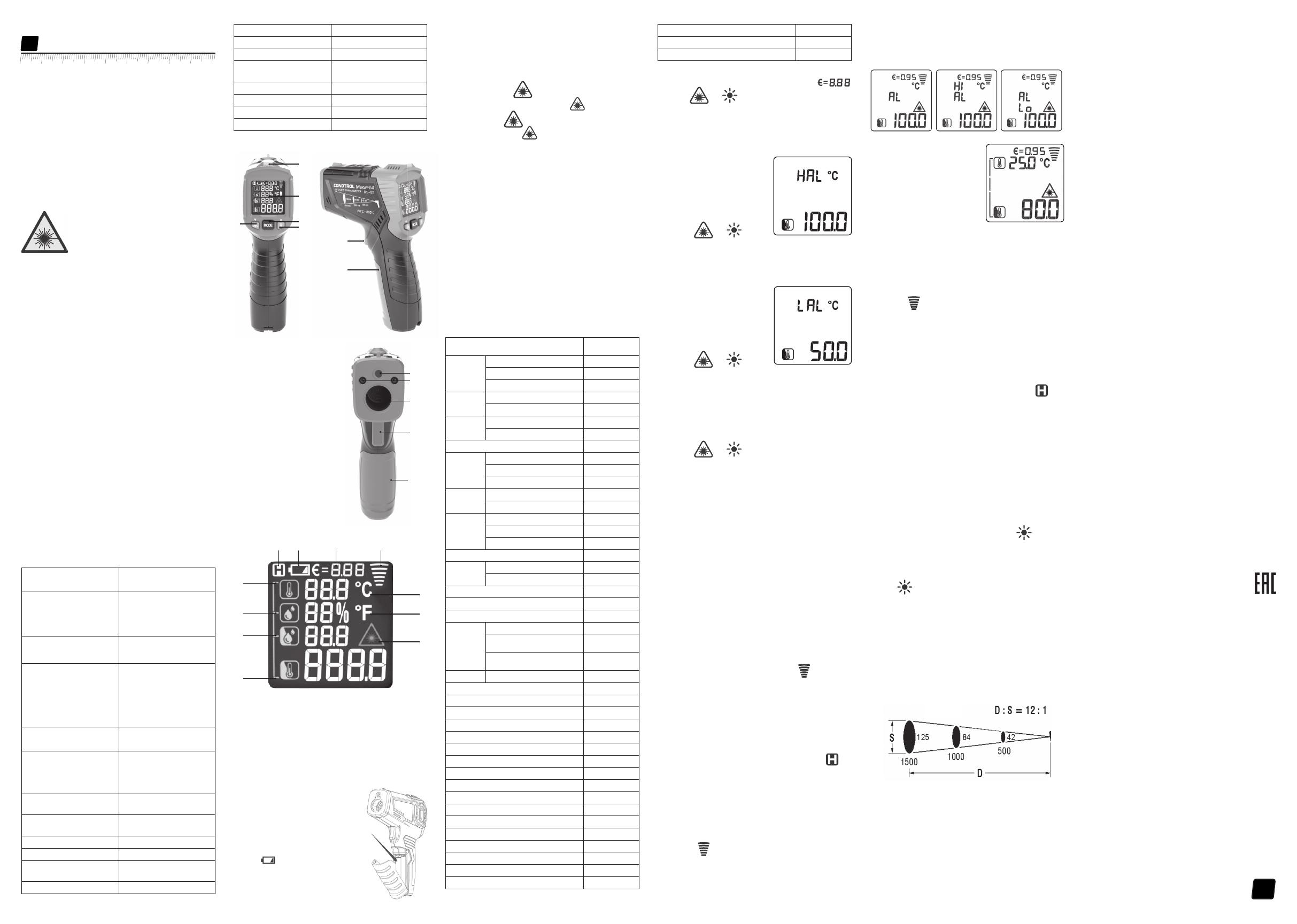
4
Поздравляем с приобретением инфракрасного пирометра
Maxwell 4 CONDTROL.
Перед первым использованием прибора, пожалуйста,
внимательно ознакомьтесь с правилами безопасности,
приведенными в данном руководстве по эксплуатации.
УКАЗАНИЯ ПО ТЕХНИКЕ БЕЗОПАСНОСТИ
Внимание! Данная инструкция по эксплуатации является
неотъемлемой частью Вашего прибора. Прежде чем приступить
к работе с прибором, внимательно прочтите инструкцию. При
передаче прибора во временное пользование обязательно
прилагайте к нему данную инструкцию.
— Не используйте прибор не по назначению.
— Не удаляйте наклейки и таблички и предохраняйте их от
стирания, т.к. они содержат информацию о безопасной
эксплуатации прибора.
Лазерное излучение!
Не направляйте в глаза
Лазер класса 2
<1 мВт, 630—670нм
IEC 60825-1: 2007-03
— Не смотрите в лазерный луч, а также в его отражение, как
незащищенным глазом, так и через оптические устройства.
Не направляйте лазерный луч на людей и животных без
необходимости. Вы можете их ослепить.
— Защита глаз обычно осуществляется путем отведения взгляда
или закрытием век.
— Не допускайте посторонних лиц в зону эксплуатации прибора.
— Храните прибор вне досягаемости детей и посторонних лиц.
— Не разбирайте и не ремонтируйте прибор самостоятельно.
Обслуживание и ремонт следует поручать только
квалифицированным специалистам и с применением
оригинальных запасных частей.
— Запрещается эксплуатация прибора во взрывоопасной среде,
вблизи легковоспламеняющихся материалов.
-Не допускайте нагревания элементов питания во избежание
риска взрыва и вытекания электролита. При попадании
жидкости на кожу немедленно промойте пораженный участок
водой с мылом. В случае попадания в глаза, промойте их чистой
водой в течение 10 минут, затем обратитесь к врачу.
НАЗНАЧЕНИЕ ПРИБОРА
Пирометр Maxwell 4 CONDTROL предназначен для измерения
температуры поверхностей объектов бесконтактным способом.
Он оснащен датчиками температуры и влажности воздуха
в помещении, инфракрасным сенсором для измерения
температуры поверхности объекта, благодаря чему способен
определять «мостики холода» и места возможного образования
плесени. Одним нажатием кнопки можно распознать плохо
утепленные участки окон или обнаружить негерметичные места
в наружных стенах. Функция ультрафиолетовой подсветки
позволяет проводить диагностику систем кондиционирования.
КОМПЛЕКТАЦИЯ
Инфракрасный пирометр — 1шт.
Элементы питания (9В 6F22) — 1 шт.
Инструкция — 1 шт.
ТЕХНИЧЕСКИЕ ХАРАКТЕРИСТИКИ
Диапазон измерений
температуры поверхности
-50 °С…800 °С
-58 °F…1472 °F
Погрешность измерений
температуры
-50 °С…0 °С /
-58 °F…32 °F:
0 °С....800 °С /
32 °F…1472 °F:
±3 °С
±2.0%
или ±2°C
поверхности
Диапазон измерений
температуры окружающей
среды
-10 °C…60 °C / 14 °F…140 °F
Погрешность измерений
температуры окружающей
среды
-10 °C…0 °C/
14 °F…32 °F: ±1.5 °C
0 °C…40°C /
32 °F…113 °F: ±1.0 °C
40 °C…60°C /
113 °F…140 °F: ±1.5 °C
Диапазон измерений
относительной влажности 0% …100%
Погрешность измерения
относительной влажности
0%…20%: ±5.0%
20%…80%: ±4.0%
80%…100%: ±5.0%
Диапазон измерения точки
росы -10°C…50°C / 14°F…122°F
Погрешность определения
температуры точки росы ±1.5°C / 3°F
Оптическое разрешение 12:1
Время отклика <0,5 cек
Автоматическое выключение
прибора 30 сек
Спектральный диапазон 8...14 мкм
Коэффициент излучения 0,1…1,0 регулируемый
Температура эксплуатации 0 °С …40 °С
Температура хранения -10 °C …60 °C
Допустимая относительная
влажность
10…95% — рабочий режим
< 80% — хранение
Элементы питания 1 x 9В 6F22
Тип лазера Класс II, 630—670 нм, <1 мВт
Габариты 104х164х47 мм
Вес 155 г
ОПИСАНИЕ ПРИБОРА
1 – Световой индикатор
2 – Дисплей
3 – Кнопка активации/
деактивации лазерного
указателя/настройка значения
коэффициента излучения
(уменьшение значения)
4 – Кнопка выбора режима
работы
5 – Кнопка включения/
выключения ультрафиолетовой
подсветки/настройка значения
коэффициента излучения
(увеличение значения)
6 – Окно лазерного указателя
7 – Окно ультрафиолетовой
подсветки
8 – Инфракрасный датчик
9 – Триггер
10 – Крышка батарейного отсека
Дисплей
УХОД И ЭКСПЛУАТАЦИЯ
Внимание! Прибор является точным оптико-механическим
устройством и требует бережного обращения.
Соблюдение следующих рекомендаций продлит срок службы
прибора:
— Оберегайте прибор от ударов, падений, сильных вибраций,
не допускайте попадания внутрь прибора влаги, строительной
пыли, посторонних предметов.
— Не подвергайте прибор воздействию экстремальных
температур
— В случае попадания в прибор влаги в первую очередь выньте
элементы питания, затем обратитесь в сервисный центр.
— Не храните и не используйте прибор в течение длительного
времени в условиях повышенной влажности.
— Чистку прибора следует производить влажной мягкой
салфеткой.
— Содержите оптику прибора в чистоте и оберегайте от
механических повреждений.
Несоблюдение следующих правил может привести к вытеканию
электролита из элементов питания и порче прибора:
— Вынимайте элементы питания из прибора, если он не
используется в течение длительного времени.
— Не оставляйте в приборе разряженные элементы питания.
ГАРАНТИЙНЫЕ ОБЯЗАТЕЛЬСТВА
Гарантийный период составляет 12 месяцев с даты продажи.
Срок службы прибора — 36 месяцев.
Производитель гарантирует соответствие прибора заявленным
характеристикам при условии соблюдения правил эксплуатации
и хранения, установленных в настоящем руководстве по
эксплуатации.
Гарантия распространяется на недостатки и дефекты,
являющиеся заводским браком или возникшие в результате
заводского брака.
Гарантия не распространяется на неисправности, возникшие в
результате интенсивной эксплуатации и естественного износа,
нарушений правил эксплуатации, самостоятельного ремонта,
а также на элементы питания. Гарантия также не покрывает
транспортные расходы, связанные с возвратом прибора в
ремонт.
Производитель оставляет за собой право вносить изменения в
конструкцию, алгоритмы работы, комплектацию прибора без
предварительного уведомления.
СЕРВИС И КОНСУЛЬТАЦИОННЫЕ УСЛУГИ
Контакты для связи, консультации можно получить на сайте
www.condtrol.ru
УТИЛИЗАЦИЯ
Отслужившие свой срок инструменты, принадлежности и
упаковка должны быть утилизированы согласно действующим
законам вашей страны.
Не выбрасывайте аккумуляторы/батареи в коммунальный
мусор, не бросайте их в огонь или воду. Аккумуляторы/батареи
следует собирать и сдавать на рекуперацию или на экологически
чистую утилизацию.
Только для стран-членов ЕС:
Не выбрасывайте инструменты в коммунальный мусор!
Согласно Европейской Директиве 2002/96/ЕС о старых
электрических и электронных инструментах и приборах и ее
претворению в национальное право, отслужившие свой срок
измерительные инструменты должны собираться отдельно и
быть переданы на экологически чистую рекуперацию отходов.
Неисправные или пришедшие в негодность аккумуляторы/
батареи должны быть утилизированы согласно Директиве
2006/66/ЕС.
1 – Температура окружающей среды
2 – Уровень относительной влажности
3 – Температура точки росы
4 – Температура поверхности
5 – Индикатор активированного лазерного указателя
6 – Единица измерения температуры – Фаренгейты
7 – Единица измерения температуры — Цельсия
8 – Индикатор активного измерения
9 – Коэффициент излучения
10 – Индикатор питания
11 – Индикатор удержания данных об измерении на дисплее
УСТАНОВКА/ЗАМЕНА
ЭЛЕМЕНТОВ ПИТАНИЯ
Откройте батарейный отсек.
Установите элемент питания,
соблюдая полярность. Установите
крышку батарейного отсека
обратно до щелчка.
При появлении на дисплее
символа , сигнализирующего
о том, что элемент питания
разряжен, необходимо заменить
элемент питания на новый.
Maxwell 4
Руководство по эксплуатации
Инфракрасный пирометр
RU
1
2
4
5
3
9
10
6
8
9
10
7
11 10 9 8
1
3
4
6
5
2
7
символа , сигнализирующего
ВКЛЮЧЕНИЕ/ВЫКЛЮЧЕНИЕ ПРИБОРА
Нажмите на триггер, чтобы включить прибор. Прибор готов к
работе. Выключение происходит автоматически через 30 секунд
после последнего действия.
НАСТРОЙКИ ПРИБОРА
1) Лазерный указатель
Нажмите кнопку , чтобы активировать лазерный
указатель*. На дисплее появится символ .
Нажмите кнопку , чтобы деактивировать лазерный
указатель. Символ на дисплее исчезнет. Лазерный
указатель предназначен только для прицеливания и может
быть отключен при работе на малых расстояниях для экономии
заряда батареи.
*Лазерный указатель включается только тогда, когда нажат
триггер.
2) Настройка коэффициента излучения
Все объекты излучают тепловую энергию. Объем излучаемой
энергии зависит от температуры поверхности и коэффициента
излучения объекта. Пирометр измеряет интенсивность
излучения и использует ее для расчета значений температуры
объекта. Объекты с разными поверхностями при равной
температуре излучают разное количество тепловой энергии.
Большинство предметов и материалов, например, окрашенные
металлы, дерево, вода, кожа, ткань обладают высоким
коэффициентом теплового излучения (0,9 и более) и излучают
энергии больше, чем блестящие поверхности и неокрашенные
металлы, коэффициент теплового излучения которых меньше
0,6. Настройка коэффициента излучения позволяет прибору
учесть эту особенность и минимизировать погрешность
измерения.
Таблица 1.
Коэффициент излучения различных материалов
Материал Коэффициент
излучения
Алюминий Оксидированный 0.2~0.4
A3003 сплав (оксидрованный) 0.3
A3003 сплав (шероховатый) 0.1~0.3
Латунь Шлифованная 0.3
Оксидированная 0.5
Медь Оксидированная 0.4~0.8
Соединительная плата 0.6
Хастеллой (коррозионностойкий сплав) 0.3~0.8
Ферро—
никель
Оксидированный 0.7~0.95
Абразивоструйная обработка 0.3~0.6
Электролитическая полировка 0.15
Железо Оксидированное 0.5~0.9
Ржавое 0.5~0.7
Чугунное
литье
Оксидированный 0.6~0.95
Неокисленный 0.2
Сплавное литье 0.2~0.3
Пассивированное литье 0.9
Свинец Шероховатый 0.4
Оксидированный 0.2~0.6
Оксидированный молибден 0.2~0.6
Оксидированный никель 0.2~0.5
Черная платина 0.9
Сталь Холодный прокат 0.7~0.9
Шлифованная стальная
пластина
0.4~0.6
Полированная стальная
пластина
0.1
Цинк Оксидированный 0.1
Асбест 0.95
Асфальт 0.95
Базальт 0.7
Уголь (неокисленный) 0.8…0.9
Графит 0.7…0.8
Углеродистый кремний 0.9
Керамика 0.95
Глина 0.95
Бетон 0.95
Ткань 0.95
Листовое стекло 0.85
Гравий 0.95
Гипс 0.8…0.95
Лед 0.98
Известняк 0.98
Бумага 0.95
Пластик 0.95
Почва 0.9…0.98
Вода 0.93
Древесина 0.9…0.95
Нажмите и удерживайте кнопку MODE в течение 2 секунд для
входа в меню настроек. На дисплее появится символ .
Кнопками и выполните настройку коэффициента
эмиссии. Для выхода из настроек нажмите на триггер или
нажмите и удерживайте кнопку MODE в течение 2 секунд.
3) Настройка температурного диапазона
Верхний предел температурного диапазона
Нажмите и удерживайте кнопку
MODE в течение 2 секунд
для входа в меню настроек.
Однократным нажатием кнопки
MODE выберите настройку
верхнего предела температурного
диапазона. На дисплее появится
символ HAL.
Кнопками и
выполните настройку верхнего предела температурного
диапазона. Для выхода из настроек нажмите на триггер или
нажмите и удерживайте кнопку MODE в течение 2 секунд.
Нижний предел температурного диапазона
Нажмите и удерживайте кнопку
MODE в течение 2 секунд
для входа в меню настроек.
Двукратным нажатием кнопки
MODE выберите настройку
нижнего предела температурного
диапазона. На дисплее появится
символ LAL.
Кнопками и
выполните настройку нижнего предела температурного
диапазона. Для выхода из настроек нажмите на триггер или
нажмите и удерживайте кнопку MODE в течение 2 секунд.
4) Выбор единиц измерения
Нажмите и удерживайте кнопку MODE в течение 2 секунд
для входа в меню настроек. Нажмите кнопку MODE 3 раза. На
дисплее появится символ 0C.
Кнопками и выберите необходимые единицы
измерения (°C – градусы Цельсия / °F – градусы Фаренгейта).
Для выхода из настроек нажмите на триггер или нажмите и
удерживайте кнопку MODE в течение 2 секунд.
РЕЖИМЫ РАБОТЫ
1) Определение точки росы
Точка росы свидетельствует о том, при какой температуре
начинает конденсироваться содержащийся в воздухе водяной
пар. Точка росы зависит от относительной влажности воздуха и
температуры окружающей среды.
Если температура поверхности ниже точки росы, то на
этой поверхности начинает конденсироваться вода. Чем
больше разница между обеими температурами и чем выше
относительная влажность воздуха, тем сильнее конденсация.
Образующийся на поверхности конденсат — главная причина
образования плесени.
В режиме определения точки росы измеряются температура
окружающей среды и относительная влажность воздуха. На
основании этих двух значений рассчитывается температура
точки росы. Кроме того, измеряется температура поверхности.
Точка росы сравнивается с температурой поверхности, а
результат позволяет оценить вероятность образования плесени.
Включите прибор. Наведите прибор на цель и нажмите
на триггер. При удержании триггера прибор переходит в
режим непрерывного измерения (сканирования), на дисплее
появляется символ активного измерения . Значения
измерения на дисплее непрерывно актуализируются.
Если в процессе измерения световой индикатор горит
зеленым, опасности образования плесени нет. Если в процессе
измерения световой индикатор горит желтым, есть вероятность
образования плесени в области измерения. Если в процессе
измерения световой индикатор горит красным, существует
повышенная опасность образования плесени в области
измерения.
При отпускании триггера прибор фиксирует последнее
измеренное значение. На дисплее появляется символ .
2) Выход за пределы установленного температурного
диапазона
В данном режиме прибор измеряет только температуру
поверхности.
Включите прибор. Однократно нажмите на кнопку MODE.
Наведите прибор на цель и нажмите на триггер. При удержании
триггера прибор переходит в режим непрерывного измерения
(сканирования), на дисплее появляется символ активного
измерения . Значения измерения на дисплее непрерывно
актуализируются.
Если в процессе измерения температура поверхности
превышает верхнюю установленную границу диапазона, на
дисплее появляется символ Hi. Если температура поверхности
ниже нижней установленной границе диапазона, на дисплее
появляется символ Lo .
3) Обнаружение теплового моста
Тепловой мост — локализованный
участок в элементах теплоизоляции
помещений, на которых происходит
интенсивная передача тепла с более
теплой стороны к более холодной.
Наличие тепловых мостов служит
причиной повышенных потерь
тепла. Более низкая температура
внутренней поверхности в области
теплового моста по сравнению
с температурой поверхности неповрежденных участков
обуславливает риск конденсации и, как результат, образования
плесени.
Включите прибор. Нажмите кнопку MODE 2 раза для выбора
режима обнаружения теплового моста.
Наведите прибор на цель и нажмите на триггер. При удержании
триггера прибор переходит в режим непрерывного измерения
(сканирования), на дисплее появляется символ активного
измерения . Значения измерения на дисплее непрерывно
актуализируются.
Если температура окружающей среды близка к значению
температуры поверхности объекта, тепловые мосты
отсутствуют, световой индикатор горит зеленым. Если есть
вероятность наличия теплового моста в области измерения,
световой индикатор горит желтым. Если световой индикатор
горит красным, в области измерения имеется тепловой мост, что
является свидетельством плохой изоляции.
При отпускании триггера прибор фиксирует последнее
измеренное значение. На дисплее появляется символ .
4) Режим ультрафиолетовой подсветки
Пирометр Maxwell 4 имеет функцию ультрафиолетовой
подсветки, которая позволяет проводить диагностику системы
кондиционирования автомобиля на предмет утечки хладагента.
Главное преимущество данного метода — максимальная
простота диагностики.
Он основан на использовании красителя, который смешивается
с фреоном и закачивается внутрь системы кондиционирования.
Перед началом диагностики необходимо выполнить полную
заправку системы. После заправки система кондиционирования
может использоваться на полную мощность. При ухудшении
работы кондиционера необходимо провести диагностику.
Для получения наиболее точного результата рекомендуется
проводить диагностику в темном помещении.
Заведите двигатель и включите кондиционер. Включите
прибор. Кратковременным нажатием кнопки включите
ультрафиолетовую подсветку и с ее помощью осмотрите все
компоненты системы.
Те места, откуда вытекает фреон, можно легко увидеть. Они
будут светиться подтеками желто—зеленого цвета.
После окончания диагностики кратковременным нажатием
кнопки выключите ультрафиолетовую подсветку.
ОПТИЧЕСКОЕ РАЗРЕШЕНИЕ
С увеличением расстояния от прибора до цели увеличивается
размер пятна на измеряемой поверхности. Чтобы определить
размер пятна измерения (S), нужно расстояние от прибора до
цели (D) разделить на 12.
Лазерные указатели являются ориентиром, чтобы определить
размер и положение пятна измерения.
Единицы измерения — мм
125 84 42 — пятно (S)
1500 1000 500 — расстояние (D)
Почти за вековую историю существования японская компания Makita прекрасно зарекомендовала себя на мировом рынке. Электроинструменты, генераторы и садовая техника этого производителя пользуются популярностью у профессионалов и любителей, которые отдают предпочтение надежности, высокой эффективности и максимальному комфорту в работе.
Многие по привычке, выработанной вследствие наплыва китайских товаров сомнительного качества в 90-е годы прошлого века, до сих пор осторожно интересуются у продавцов о стране-изготовителе той или иной модели электроинструмента Макита и, услышав слово «Китай», отправляются восвояси с надеждой найти то же самое но с лейблом «made in…» где-нибудь в другом месте. И абсолютно зря. Дело в том, что на сегодняшний день предприятия концерна Makita рассредоточены по всему миру – в Японии, Германии, Румынии, Австрии, Великобритании, Америке, Бразилии и Китае. И производство распределено таким образом, что определенные модели выпускаются только на конкретных предприятиях. Так в Китае сегодня налажено производство аккумуляторных дрелей-шуруповертов, угловых шлифовальных машин, других шлифователей, отдельных моделей сабельных пил, перфораторов и пр.
Например, бесполезно искать в продаже перфоратор Makita HR2450, произведенный в Германии или Великобритании. Этот инструмент сходит только с конвейеров одного из двух китайских заводов, о чем свидетельствуют литеры «Y» или «K» в конце серийного номера на шильдике самого инструмента (упаковка и некоторые комплектующие могут быть от другого производителя).
Тот факт, что эта информация открыта, лишний раз подтверждает прозрачность экономической политики концерна Макита и ответственность за качество. Все новые технологии разрабатываются на родине бренда – в Японии, и совершенствуются на заводе в Оказаки, и только после этого под неусыпным контролем квалифицированных специалистов внедряются в производство на других предприятиях, в том числе и на китайских.
Что касается стандартов качества, то они едины для всей продукции Makita, независимо от географии производителя. Все заводы имеют сертификаты, подтверждающие соответствие наличествующей системы управления качеством нормам ISO 9000:2000, направленным на удовлетворение интересов потребителей.
Таким образом, качество китайской Макиты, если только это не дешевая подделка, находится на одном уровне с японской, английской или, к примеру, немецкой. А чтобы исключить подделку, достаточно воспользоваться услугами официального дилера Makita. Например, услугами компании МакитаПро.