
|
(495) 984-51-05 Москва |
Документация | Электроприводы переменного тока
Commander C200 | C300
Commander C200 | C300 — Руководство пользователя по управлению
Commander C200 | C300 — Руководство по установке электропитания | Габариты с 1 по 4
Commander C200 | C300 — Руководство по установке электропитания | Габариты с 5 по 6
Commander C200 | C300 — Руководство по установке электропитания | Габариты с 7 по 10
Commander C200 | C300 — Краткое руководство пользователя | Габариты с 1 по 4
Commander C200 | C300 — Краткое руководство пользователя | Габариты с 5 по 9
Commander C200 — Краткое руководство пользователя | Габариты с 1 по 4
Commander SK — Commander C200 — Брошюра
Commander C200 — Брошюра
Commander C200 — Справочное руководство по параметрам
Commander C300 — Справочное руководство по параметрам
Commander SK
Commander SK — Приступаем к работе (габариты 2 — 6) (pdf, 6286Kb)
Commander SK — Расширенное руководство пользователя (pdf, 5816Kb)
Commander SK — Брошюра (pdf, 8226Kb)
Commander SK — Datasheet size A (pdf, 300Kb)
Commander SK — Datasheet size B (pdf, 353Kb)
Commander SK — Datasheet size C (pdf, 552Kb)
Commander SK — Datasheet size D (pdf, 242Kb)
Commander SK — Технические характеристики (pdf, 8252Kb)
Руководство по замене Commander SE на Commander SK (pdf, 2167Kb)
Commander SK — Руководство пользователя (приступаем к работе, габариты 2 — 6) (pdf, 7523Kb)
Commander SK — Руководство пользователя (приступаем к работе, габариты A — D) (pdf, 1202Kb)
Commander SK — Руководство пользователя (все габариты) (pdf, 11299Kb)
Commander SE (устаревшая модель) — Руководство пользователя (pdf, 1216Kb)
Commander SE (устаревшая модель) — Расширенное руководство пользователя (pdf, 4557Kb)
Commander SE (устаревшая модель) — Брошюра (pdf, 582Kb)
Commander SX
Commander SX — Расширенное руководство пользователя (pdf, 2368Kb)
Commander SX — Брошюра (pdf, 234Kb)
Commander SX — Тормозной контактор (pdf, 137Kb)
Commander SX — Модуль тормозного контактора со входом защитного отключения (pdf, 179Kb)
Commander SX — Тормозной резистор (pdf, 542Kb)
Commander SX — Разводка кабелей (pdf, 604Kb)
Commander SX — Разъединитель (pdf, 675Kb)
Commander SX — Модуль подключения энкодера (pdf, 117Kb)
Commander SX — LCD (pdf, 259Kb)
Commander SX — Защита (pdf, 125Kb)
Commander SX — Руководство пользователя (pdf, 2488Kb)
Commander SX — Карта памяти (pdf, 154Kb)
Commander SX — Опции (pdf, 360Kb)
Unidrive SP
Unidrive SP — Брошюра (pdf, 5453Kb)
Unidrive SP — Руководство пользователя (pdf, 44584Kb)
Unidrive SP — Расширенное руководство пользователя (pdf, 10602Kb)
Unidrive SP — Брошюра по приводам шкафного исполнения от 90 до 675 кВт (pdf, 1806Kb)
Unidrive SPM — Руководство пользователя по модульным преобразователям (pdf, 28999Kb)
Unidrive SP — Руководство по использованию преобразователей для систем рекуперации энергии (pdf, 16382Kb)
Unidrive SP — Контроллер позиционирования APC (Advanced Position Controller) (pdf, 2035Kb)
Unidrive SPM — Брошюра по модульным приводам SPM (pdf, 2138Kb)
Руководство по замене Unidrive на Unidrive SP (pdf, 13641Kb)
Руководство по замене Unidrive SP на Unidrive M600 | M700 (pdf, 5054Kb)
Unidrive SPM — Руководство по модульным преобразователям (pdf, 23528Kb)
Unidrive SP — Брошюра 0-й габарит (pdf, 2174Kb)
Unidrive SP — Руководство по применению с лифтами (pdf, 7924Kb)
Commander GP (устаревшая модель) — Руководство пользователя (pdf, 2721Kb)
Unidrive SP — Расширенное руководство пользователя (pdf, 5891Kb)
Unidrive SP — Функция безопасного останова (pdf, 3830Kb)
Unidrive SP — Руководство пользователя для приводов шкафного исполнения (габариты 6 — 9) (pdf, 20409Kb)
Unidrive SP — Руководство по рекуперации энергии в сеть (pdf, 11208Kb)
Контроллер управления модулями SPM (pdf, 2685Kb)
Unidrive SP шкафного исполнения до 1600 кВт — Брошюра (pdf, 2825Kb)
Affinity
Affinity — Брошюра (pdf, 2033Kb)
Affinity — Руководство пользователя (pdf, 23139Kb)
Affinity — Расширенное руководство пользователя (pdf, 5416Kb)
Affinity — Руководство по настройке макросов (pdf, 616Kb)
Unidrive M
Unidrive M100
Unidrive M100 — Брошюра
Unidrive M100 — Руководство пользователя
Unidrive M100 — Краткое руководство пользователя
Unidrive M100 — M400 — Руководство по установке электропитания | Габариты с 1 по 4
Unidrive M — Руководство по установке электропитания | Габариты с 5 по 6
Unidrive M — Руководство по установке электропитания | Габариты с 7 по 10
Unidrive M200
Unidrive M200 — Брошюра
Unidrive M200 — Руководство пользователя
Unidrive M200 — Краткое руководство пользователя (габариты 1 — 4)
Unidrive M200 — Краткое руководство пользователя (габариты 5 — 6)
Unidrive M100 — M400 — Руководство по установке электропитания | Габариты с 1 по 4
Unidrive M — Руководство по установке электропитания | Габариты с 5 по 6
Unidrive M — Руководство по установке электропитания | Габариты с 7 по 10
Unidrive M300
Unidrive M300 — Брошюра
Unidrive M300 — Руководство пользователя
Unidrive M300 — Краткое руководство пользователя (габариты 1 — 4)
Unidrive M300 — Краткое руководство пользователя (габариты 5 — 6)
Unidrive M100 — M400 — Руководство по установке электропитания | Габариты с 1 по 4
Unidrive M — Руководство по установке электропитания | Габариты с 5 по 6
Unidrive M — Руководство по установке электропитания | Габариты с 7 по 10
Unidrive M400
Unidrive M400 — Брошюра
Unidrive M400 — Руководство пользователя
Unidrive M400 — Краткое руководство пользователя (габариты 1 — 4)
Unidrive M400 — Краткое руководство пользователя (габариты 5 — 
Unidrive M100 — M400 — Руководство по установке электропитания | Габариты с 1 по 4
Unidrive M — Руководство по установке электропитания | Габариты с 5 по 6
Unidrive M — Руководство по установке электропитания | Габариты с 7 по 10
Unidrive M600
Unidrive M600 — Брошюра
Unidrive M600 — Руководство пользователя
Unidrive M600 — Краткое руководство пользователя
Unidrive M — Руководство по установке электропитания | Габариты с 5 по 6
Unidrive M — Руководство по установке электропитания | Габариты с 7 по 10
Unidrive M700
Unidrive M700 | M701 — Брошюра
Unidrive M700 | M701 — Руководство пользователя
Unidrive M700 | M701 — Краткое руководство пользователя
Unidrive M — Руководство по установке электропитания | Габариты с 5 по 6
Unidrive M — Руководство по установке электропитания | Габариты с 7 по 10
Unidrive F300
Unidrive F300 — Брошюра
Unidrive F300 — Руководство пользователя
Unidrive F300 — Краткое руководство пользователя
|
Поддержка и помощь |
Продукция сертифицирована |
Доступность |
Сервисное обслуживание |
Оперативная доставка |
Данный сайт носит информационно-справочный характер и ни при каких условиях не является публичной офертой, которая определяется положениями Статьи 437 (2) Гражданского кодекса РФ.
You must be logged in to download files. If already registered, you can login using your email address in the text box below.
If you haven’t registered yet, please click here
User Guides |
|||||
| Title | Issue | File Type |
Size | Lang | |
|---|---|---|---|---|---|
| Commander C200-C300 Control User Guide | 2 | 8 MB | EN | Download | |
| Commander C300 PM Control User Guide | 3 | 7 MB | EN | Download | |
| KI-Keypad Plus User Guide / Installation Sheet | 3 | 550 KB | EN | Download | |
| SI-BACnet IP User Guide | 2 | 4.68 MB | EN | Download | |
| Solar Pump Solution for Commander C User Guide | 4 | 6 MB | EN | Download | |
Step By Step Guide |
|||||
| Title | Issue | File Type |
Size | Lang | |
| Commander C200-C300 (Frame 1 to 4) Step By Step Guide | 4 | 2.33 MB | Multi | Download | |
| Commander C200-C300 (Frame 5 to 9) Step By Step Guide | 5 | 11 MB | Multi | Download | |
| Commander C300 PM 1 to 4 Step by Step Guide | 3 | 2.18 MB | Multi | Download | |
| Commander C300 PM Frame 5 to 9 Step By Step Guide | 3 | 10 MB | Multi | Download | |
Installation Guides |
|||||
| Title | Issue | File Type |
Size | Lang | |
| Commander C200 & C300 Frame 1 to 4 Power Installation Guide | 5 | 6 MB | EN | Download | |
| Commander C200 & C300 Frame 5 and 6 Power Installation Guide | 8 | 8 MB | EN | Download | |
| Commander C200 & C300 Frame 7 to 9 Power Installation Guide | 13 | 12 MB | EN | Download | |
Option Module User Guides |
|||||
| Title | Issue | File Type |
Size | Lang | |
| Migration Guide from SM-Interbus to SI-Interbus | 1 | 331 KB | EN | Download | |
| SI-CANopen V2 User Guide | 3 | 2.08 MB | EN | Download | |
| SI-DeviceNet User Guide | 3 | 1.61 MB | EN | Download | |
| SI-Encoder User Guide | 2 | 937 KB | EN | Download | |
| SI-Ethercat User Guide | 5 | 2.25 MB | EN | Download | |
| SI-Ethernet User Guide | 4 | 3.00 MB | EN | Download | |
| SI-I/O User Guide | 4 | 1.73 MB | EN | Download | |
| SI-INTERBUS User Guide | 1 | 3.26 MB | EN | Download | |
| SI-POWERLINK User Guide | 1 | 4.45 MB | EN | Download | |
| SI-PROFIBUS User Guide | 4 | 2.65 MB | EN | Download | |
| SI-PROFINET V2 User Guide | 3 | 2.46 MB | EN | Download | |
| SI-Safety User Guide | 5 | 1.30 MB | EN | Download | |
| SI-Universal Encoder User Guide | 3 | 1.61 MB | EN | Download | |
Software |
|||||
| Title | Issue | File Type |
Size | Lang | |
| Connect Software v02.23.01 | 02.23.01 | zip | 539 MB | EN | Download |
| CTScope v02.06.05 | v02.06.05 | zip | 33 MB | EN | Download |
| Machine Control Studio PLC Programming Software v01.12.04 | v01.12.04 | zip | 1320 MB | EN | Download |
2D Drawings |
|||||
| Title | Issue | File Type |
Size | Lang | |
| Commander C200-C300 Size 01, 2D, dxf | 1 | dxf | 3.89 MB | EN | Download |
| Commander C200-C300 Size 02, 2D, dxf | 1 | dxf | 3.97 MB | EN | Download |
| Commander C200-C300 Size 03, 2D, dxf | 1 | dxf | 4.58 MB | EN | Download |
| Commander C200-C300 Size 04, 2D, dxf | 1 | dxf | 4.41 MB | EN | Download |
| Commander C200-C300 Size 05, 2D, dxf | 1 | dxf | 7 MB | EN | Download |
| Commander C200-C300 Size 06, 2D, dxf | 1 | dxf | 6 MB | EN | Download |
| Commander C200-C300 Size 07, 2D, dxf | 1 | dxf | 6 MB | EN | Download |
| Commander C200-C300 Size 08, 2D, dxf | 1 | dxf | 7 MB | EN | Download |
| Commander C200-C300 Size 9A, 2D, dxf | 1 | dxf | 3.13 MB | EN | Download |
| Commander C200-C300 Size 9E 10E, 2D, dxf | 1 | dxf | 3.88 MB | EN | Download |
3D Drawings |
|||||
| Title | Issue | File Type |
Size | Lang | |
| Commander C200-C300 Size 01, 3D, stp | 1 | stp | 26 MB | EN | Download |
| Commander C200-C300 Size 02, 3D, stp | 1 | stp | 24 MB | EN | Download |
| Commander C200-C300 Size 03, 3D, stp | 1 | stp | 24 MB | EN | Download |
| Commander C200-C300 Size 04, 3D, stp | 1 | stp | 27 MB | EN | Download |
| Commander C200-C300 Size 05, 3D, stp | 1 | stp | 103 MB | EN | Download |
| Commander C200-C300 Size 06, 3D, stp | 1 | stp | 109 MB | EN | Download |
| Commander C200-C300 Size 07, 3D, stp | 1 | stp | 51 MB | EN | Download |
| Commander C200-C300 Size 08, 3D, stp | 1 | stp | 37 MB | EN | Download |
| Commander C200-C300 Size 9A, 3D, stp | 1 | stp | 29 MB | EN | Download |
| Commander C200-C300 Size 9E 10E, 3D, stp | 1 | stp | 74 MB | EN | Download |
Installation Sheets |
|||||
| Title | Issue | File Type |
Size | Lang | |
| AI-485 Adaptor Installation Sheet | 1 | 314 KB | EN | Download | |
| AI-Backup Adapter Installation Sheet | 3 | 313 KB | EN | Download | |
| Conduit Box Size 03-04 Installation Sheet UL for Commander C200-C300, E300, F300, F600, H300, Unidrive M200-M702, HS70-HS72 | 2 | 477 KB | EN | Download | |
| Conduit Box Size 05 Dual Box Installation Sheet UL for Commander C200-C300, E300, F300, F600, H300, Unidrive M200-M702, HS70-HS72 | 2 | 609 KB | EN | Download | |
| Conduit Box Size 05 Single Box Installation Sheet UL for Commander C200-C300, E300, F300, F600, H300, Unidrive M200-M702, HS70-HS72 | 3 | 597 KB | EN | Download | |
| Conduit Box Size 06 Installation Sheet UL for Commander C200-C300, E300, F300, F600, H300, Unidrive M200-M702, HS70-HS72 | 2 | 459 KB | EN | Download | |
| Conduit Box Size 07 Installation Sheet UL for Commander C200-C300, E300, F300, F600, H300, Unidrive M200-M702, HS70-HS72 | 2 | 759 KB | EN | Download | |
| Conduit Box Size 08 Installation Sheet UL for Commander C200-C300, E300, F300, F600, H300, Unidrive M200-M702, HS70-HS72 | 2 | 682 KB | EN | Download | |
| Conduit Box Size 09-10 Installation Sheet UL for Commander C200-C300 (Size 9 only), E300, F300, F600, H300, Unidrive M200-M702 | 2 | 646 KB | EN | Download | |
| Conduit Box Size 1 Installation Sheet UL for Commander C200, C300, Unidrive M100-M400, HS30 | 1 | 316 KB | EN | Download | |
| Conduit Box Size 2 Installation Sheet UL for Commander C200, C300, Unidrive M100-M400, HS30 | 1 | 408 KB | EN | Download | |
| Conduit Box Size 3 Installation Sheet UL for Commander C200, C300, Unidrive M100-M400, HS30 | 1 | 450 KB | EN | Download | |
| Conduit Box Size 4 Installation Sheet UL for Commander C200, C300, Unidrive M100-M400, HS30 | 1 | 485 KB | EN | Download | |
| Fieldbus Option Module Installation Sheet | 12 | 2.14 MB | EN | Download | |
| Remote Keypad RTC Installation Sheet | 1 | 222 KB | EN | Download | |
| Through Panel Mount Size 5 Installation Sheet for Commander C200-C300, Unidrive M200-M702, E300, F600, H300, HS70-HS72 | 4 | 1015 KB | EN | Download | |
| Through Panel Mount Size 6 Installation Sheet for Commander C200-C300, Unidrive M200-M702, E300, F600, H300, HS70-HS72 | 2 | 1.98 MB | EN | Download | |
Parameter Reference Guides |
|||||
| Title | Issue | File Type |
Size | Lang | |
| Commander C200 Parameter Reference Guide | 1.6.00.02 | zip | 11 MB | EN | Download |
| Commander C300 Parameter Reference Guide | 1.6.00.02 | zip | 11 MB | EN | Download |
GSD / GSDML Files |
|||||
| Title | Issue | File Type |
Size | Lang | |
| Commander C200 & C300 GSDML for SI-PROFINET V2 | 1 | zip | 98 KB | EN | Download |
| SI-PROFIBUS V01.04.01.06 GSD Files | V01.04.01 | zip | 19 KB | EN | Download |
| SI-PROFIBUS V01.04.04.06 GSD Files | 01040406 | zip | 143 KB | EN | Download |
EDS Files |
|||||
| Title | Issue | File Type |
Size | Lang | |
| Commander C200 & C300 EDS EtherNet/IP V01.07.XX.XX | 1 | zip | 49 KB | EN | Download |
| SI-CANopen EDS Files | v02.04.05 | zip | 10 MB | EN | Download |
| SI-CANopen V2 EDS Files V02.05.05.02 | 02050502 | zip | 13 MB | EN | Download |
| SI-DeviceNet EDS files | 01020018 | zip | 349 KB | EN | Download |
| SI-Ethernet & Onboard V1 EDS Files v01.08 | v01.08 | zip | 671 KB | EN | Download |
CMD / XML Files |
|||||
| Title | Issue | File Type |
Size | Lang | |
| SI-EtherCAT ESI files V01.09.00.12 | 01090012 | zip | 675 KB | EN | Download |
Device Descriptor Files |
|||||
| Title | Issue | File Type |
Size | Lang | |
| SI-EtherCAT ESI files V01.09.00.12 | 01090012 | zip | 675 KB | EN | Download |
Accessories Data Sheets |
|||||
| Title | Issue | File Type |
Size | Lang | |
| Dynamic Braking Resistor Data Sheet | 1 | 333 KB | EN | Download | |
Drive Drawings |
|||||
| Title | Issue | File Type |
Size | Lang | |
| Commander C200-C300 Size 01, 2D, dxf | 1 | dxf | 3.89 MB | EN | Download |
| Commander C200-C300 Size 01, 3D, stp | 1 | stp | 26 MB | EN | Download |
| Commander C200-C300 Size 02, 2D, dxf | 1 | dxf | 3.97 MB | EN | Download |
| Commander C200-C300 Size 02, 3D, stp | 1 | stp | 24 MB | EN | Download |
| Commander C200-C300 Size 03, 2D, dxf | 1 | dxf | 4.58 MB | EN | Download |
| Commander C200-C300 Size 03, 3D, stp | 1 | stp | 24 MB | EN | Download |
| Commander C200-C300 Size 04, 2D, dxf | 1 | dxf | 4.41 MB | EN | Download |
| Commander C200-C300 Size 04, 3D, stp | 1 | stp | 27 MB | EN | Download |
| Commander C200-C300 Size 05, 2D, dxf | 1 | dxf | 7 MB | EN | Download |
| Commander C200-C300 Size 05, 3D, stp | 1 | stp | 103 MB | EN | Download |
| Commander C200-C300 Size 06, 2D, dxf | 1 | dxf | 6 MB | EN | Download |
| Commander C200-C300 Size 06, 3D, stp | 1 | stp | 109 MB | EN | Download |
| Commander C200-C300 Size 07, 2D, dxf | 1 | dxf | 6 MB | EN | Download |
| Commander C200-C300 Size 07, 3D, stp | 1 | stp | 51 MB | EN | Download |
| Commander C200-C300 Size 08, 2D, dxf | 1 | dxf | 7 MB | EN | Download |
| Commander C200-C300 Size 08, 3D, stp | 1 | stp | 37 MB | EN | Download |
| Commander C200-C300 Size 9A, 2D, dxf | 1 | dxf | 3.13 MB | EN | Download |
| Commander C200-C300 Size 9A, 3D, stp | 1 | stp | 29 MB | EN | Download |
| Commander C200-C300 Size 9E 10E, 2D, dxf | 1 | dxf | 3.88 MB | EN | Download |
| Commander C200-C300 Size 9E 10E, 3D, stp | 1 | stp | 74 MB | EN | Download |
EDS & GSD Files |
|||||
| Title | Issue | File Type |
Size | Lang | |
| SI-CANopen V2 EDS Files V02.05.05.02 | 02050502 | zip | 13 MB | EN | Download |
| SI-PROFIBUS V01.04.04.06 GSD Files | 01040406 | zip | 143 KB | EN | Download |
Safety |
|||||
| Title | Issue | File Type |
Size | Lang | |
| Control Techniques Sistema Library | 2.1.0 | zip | 1.64 MB | EN | Download |
Declaration of Conformity |
|||||
| Title | Issue | File Type |
Size | Lang | |
| Control Techniques EU 20191781 Ecodesign Regulation — Energy Efficiency Indicators | 4 | 1.11 MB | EN | Download | |
| EU Declaration of Conformity — SM-Safety, SI-Safety | 2 | 106 KB | EN | Download | |
| EU Declaration of Conformity — Unidrive M, Commander, Digitax HD | 4 | 123 KB | EN | Download | |
| EU Declaration of Conformity under the Machinery Directive — Commander C300 | 2 | 20 KB | EN | Download | |
| EU Declaration of Conformity under the Machinery Directive — SI-Safety | 2 | 19 KB | EN | Download | |
| RoHS Declaration of Comformity | 203 KB | EN | Download | ||
| UKCA Declaration of Conformity — SI-Safety and SM-Safety | 2 | 85 KB | EN | Download | |
| UKCA Declaration of Conformity — Unidrive M, Commander, Digitax HD | 3 | 121 KB | EN | Download |

Original Instructions
For the purposes of compliance with the EU Machinery Directive 2006/42/EC, the English version of this manual is
the Original Instructions. Manuals in other languages are Translations of the Original Instructions.
Documentation
The information contained in this manual is believed to be correct at the time of printing and does not form part of
any contract. The manufacturer reserves the right to change the specification of the product and its performance,
and the contents of the manual, without notice.
Warranty and Liability
In no event and under no circumstances shall the manufacturer be liable for damages and failures due to misuse,
abuse, improper installation, or abnormal conditions of temperature, dust, or corrosion, or failures due to operation
outside the published ratings. The manufacturer is not liable for consequential and incidental damages. Contact the
supplier of the dive for full details of the warranty terms.
Environmental policy
Control Techniques Ltd operates an Environmental Management System (EMS) that conforms to the International
Standard ISO 14001.
Restriction of Hazardous Substances (RoHS)
The products covered by this manual comply with European and International regulations on the Restriction of Hazardous Substances including EU directive 2011/65/EU and the Chinese Administrative Measures for Restriction of
Hazardous Substances in Electrical and Electronic Products.
Disposal and Recycling (WEEE)
When electronic products reach the end of their useful life, they must not be disposed of along
with domestic waste but should be recycled by a specialist recycler of electronic equipment.
Control Techniques products are designed to be easily dismantled into their major component
parts for efficient recycling. The majority of materials used in the product are suitable for
recycling.
Product packaging is of good quality and can be re-used. Large products are packed in wooden
crates. Smaller products are packaged in strong cardboard cartons which have a high recycled
fibre content. Cartons can be re-used and recycled. Polythene, used in protective film and bags
for wrapping the product, can be recycled. When preparing to recycle or dispose of any product
or packaging, please observe local legislation and best practice.
REACH legislation
EC Regulation 1907/2006 on the Registration, Evaluation, Authorisation and restriction of Chemicals (REACH)
requires the supplier of an article to inform the recipient if it contains more than a specified proportion of any
substance which is considered by the European Chemicals Agency (ECHA) to be a Substance of Very High
Concern (SVHC) and is therefore listed by them as a candidate for compulsory authorisation.
.

Copyright
The contents of this publication are believed to be correct at the time of printing. In the interests of a commitment to
a policy of continuous development and improvement, the manufacturer reserves the right to change the
specification of the product or its performance, or the contents of the guide, without notice.
All rights reserved. No parts of this guide may be reproduced or transmitted in any form or by any means, electrical
or mechanical including photocopying, recording or by an information storage or retrieval system, without
permission in writing from the publisher.
Copyright © November 2018 Nidec Control Techniques Ltd

Contents
1 Safety information ………………………………………………………………………….11
1.1 Warnings, Cautions and Notes ……………………………………………………………………11
1.2 Important safety information. Hazards. Competence of designers and installers ..11
1.3 Responsibility …………………………………………………………………………………………… 11
1.4 Compliance with regulations ……………………………………………………………………….11
1.5 Electrical hazards ………………………………………………………………………………………12
1.6 Stored electrical charge ……………………………………………………………………………..12
1.7 Mechanical hazards ………………………………………………………………………………….. 12
1.8 Access to equipment ………………………………………………………………………………….12
1.9 Environmental limits …………………………………………………………………………………..12
1.10 Hazardous environments ……………………………………………………………………………13
1.11 Motor ……………………………………………………………………………………………………….13
1.12 Mechanical brake control …………………………………………………………………………… 13
1.13 Adjusting parameters ………………………………………………………………………………… 13
1.14 Electromagnetic compatibility (EMC) ……………………………………………………………13
2 Product information ……………………………………………………………………….14
2.1 Model number …………………………………………………………………………………………..14
2.2 Nameplate description ……………………………………………………………………………….15
2.3 Ratings …………………………………………………………………………………………………….15
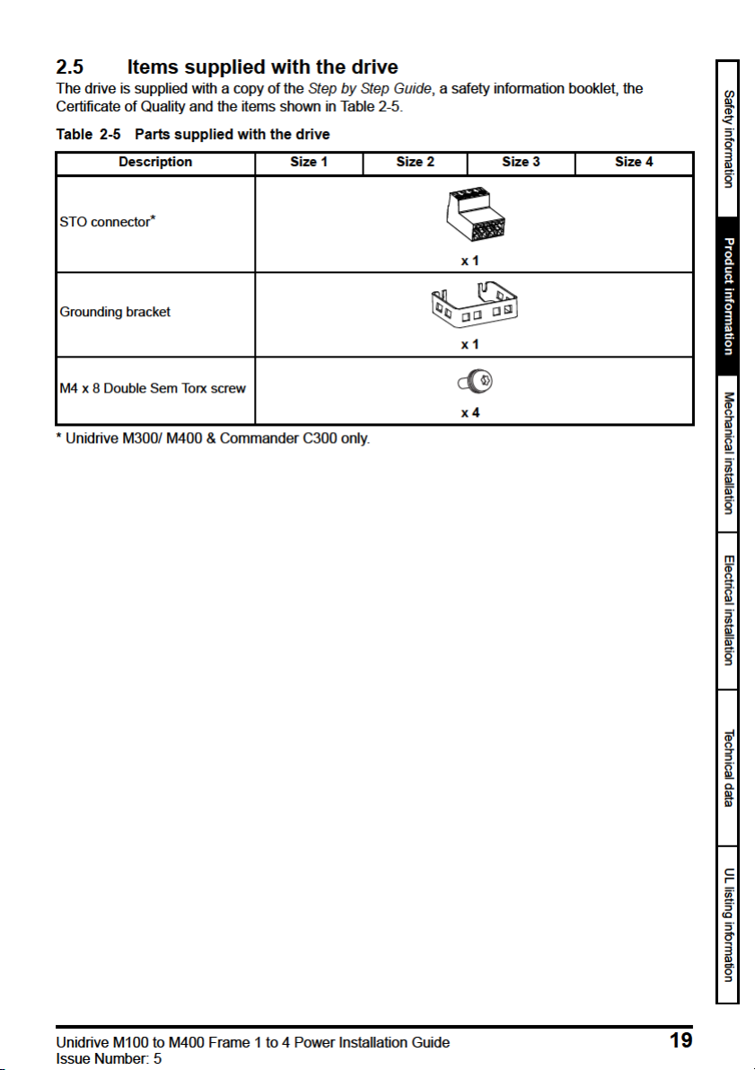
2.4 Drive features ……………………………………………………………………………………………18
2.5 Items supplied with the drive ……………………………………………………………………….19
3 Mechanical installation …………………………………………………………………..20
3.1 Safety information …………………………………………………………………………………….. 20
3.2 Planning the installation ……………………………………………………………………………..20
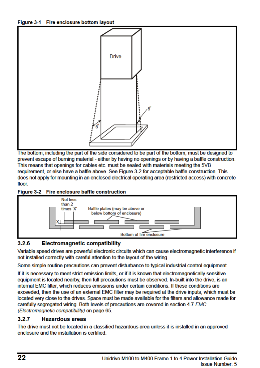
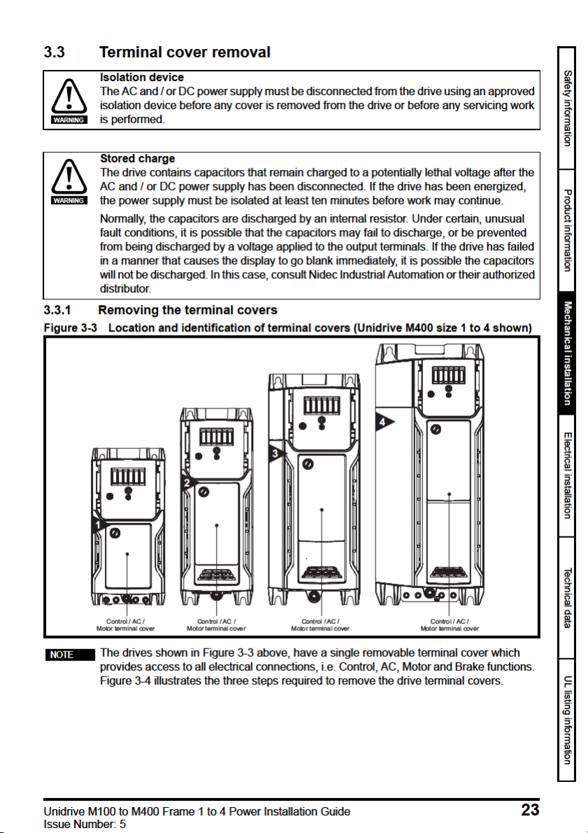
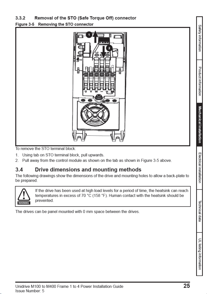
3.3 Terminal cover removal ………………………………………………………………………………23
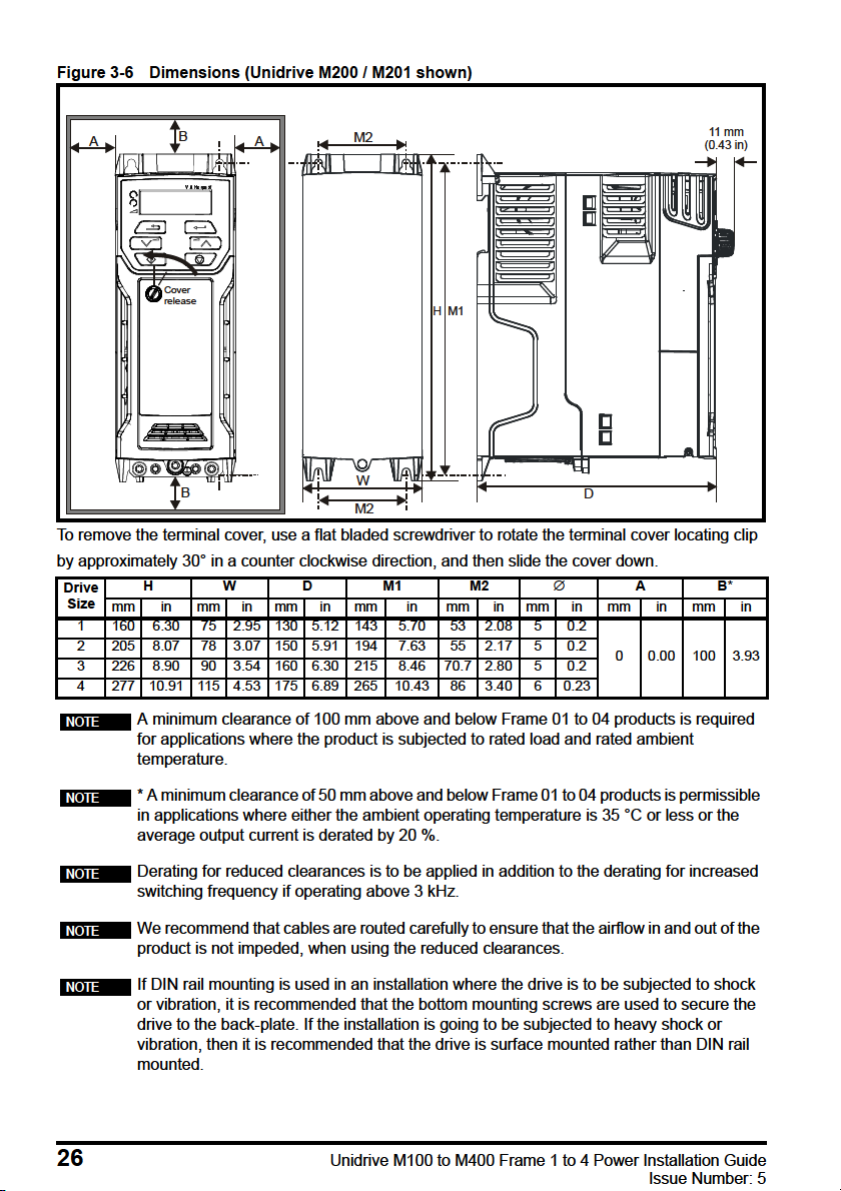
3.4 Drive dimensions and mounting methods ……………………………………………………..25
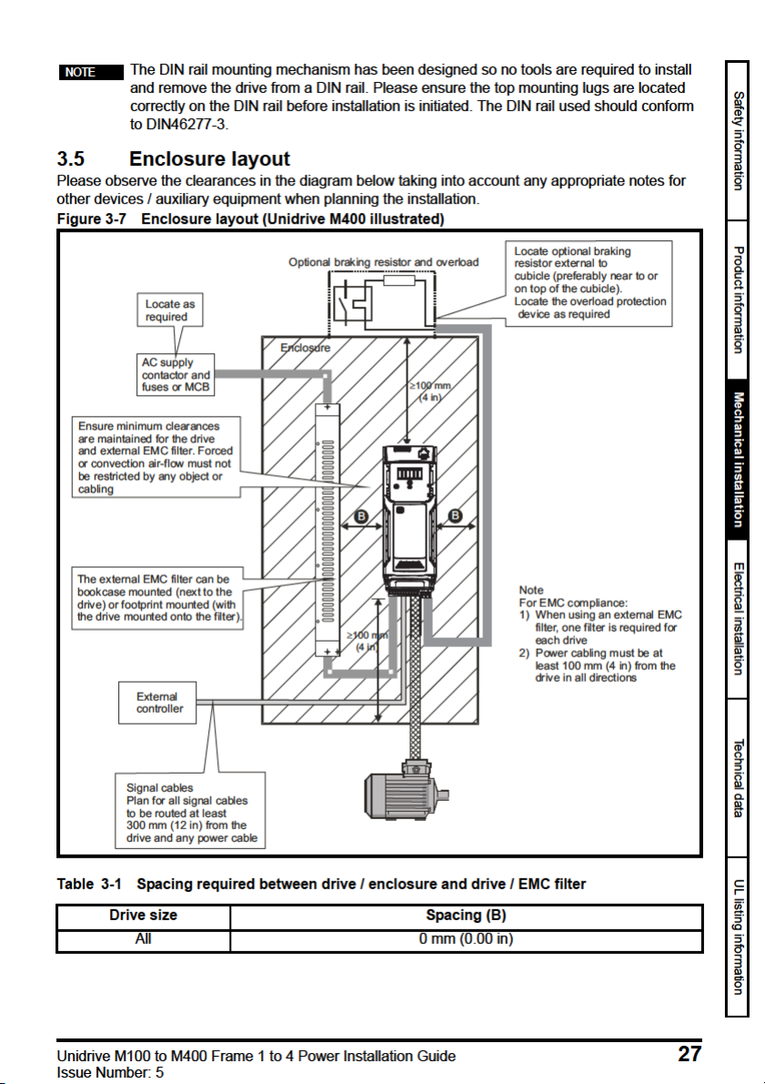
3.5 Enclosure layout ………………………………………………………………………………………..27
3.6 Heatsink fan operation ……………………………………………………………………………….31
3.7 External EMC filter ……………………………………………………………………………………. 32
3.8 Electrical terminals …………………………………………………………………………………….37
3.9 Routine maintenance ………………………………………………………………………………… 39
4 Electrical installation ………………………………………………………………………41
4.1 Power connections …………………………………………………………………………………….42
4.2 AC supply requirements ……………………………………………………………………………..45
4.3 Ratings …………………………………………………………………………………………………….51
4.4 Output circuit and motor protection ………………………………………………………………55
4.5 Braking ……………………………………………………………………………………………………. 60
4.6 Ground leakage ………………………………………………………………………………………… 64
4.7 EMC (Electromagnetic compatibility) ……………………………………………………………65
5 Technical data ………………………………………………………………………………..79
5.1 Drive technical data ……………………………………………………………………………………79
5.2 Optional external EMC filters …………………………………………………………………….100
6 UL listing information ……………………………………………………………………103
6.1 UL file reference ………………………………………………………………………………………103
6.2 Option modules, kits and accessories …………………………………………………………103
6.3 Enclosure ratings …………………………………………………………………………………….103
6.4 Mounting ……………………………………………………………………………………………….. 103
6.5 Environment …………………………………………………………………………………………… 103
6.6 Electrical Installation ………………………………………………………………………………..104
6.7 Motor overload protection and thermal memory retention ……………………………..104
6.8 Electrical supply ………………………………………………………………………………………105
6.9 External Class 2 supply …………………………………………………………………………….105
6.10 Group Installation and Modular Drive Systems …………………………………………….105
Unidrive M100 to M400 Frame 1 to 4 Power Installation Guide
Issue Number: 5
EU Declaration of Conformity
G Williams
Vice President, Technology
Date: 17th March 2016
Nidec Control Techniques Ltd
This declaration is issued under the sole responsibility of the manufacturer. The object of the declaration is in
conformity with the relevant European Union harmonization legislation. The declaration applies to the variable
speed drive products shown below:
Model
number
aaaa Basic series
bb Frame size 01, 02, 03, 04, 05, 06, 07, 08, 09, 10, 11
c Voltage rating 1 = 100 V, 2 = 200 V, 4 = 400 V, 5 = 575 V, 6 = 690 V
ddddd Current rating Example 01000 = 100 A
e Drive format
The model number may be followed by additional characters that do not affect the ratings.
The variable speed drive products listed above have been designed and manufactured in accordance with the
following European harmonized standards:
EN 61800-5-1:2007
EN 61800-3: 2004+A1:2012
EN 61000-6-2:2005
EN 61000-6-4: 2007+A1:2011
EN 61000-3-2:2014
EN 61000-3-3:2013
EN 61000-3-2:2014 Applicable where input current < 16 A. No limits apply for professional equipment where input
power 1 kW.
These products comply with the Restriction of Hazardous Substances Directive (2011/65/EU), the Low Voltage
Directive (2014/35/EU) and the Electromagnetic Compatibility Directive (2014/30/EU).
Interpretation Nomenclature aaaa — bbc ddddde
M100, M101, M200, M201, M300, M400, M600, M700, M701, M702, F300,
H300, E200, E300, HS30, HS70, HS71, HS72, M000, RECT
A = 6P Rectifier + Inverter (internal choke), D = Inverter, E = 6P Rectifier +
Inverter (external choke), T = 12P Rectifier + Inverter (external choke)
Adjustable speed electrical power drive systems — Part 5-1: Safety requirements Electrical, thermal and energy
Adjustable speed electrical power drive systems — Part 3: EMC requirements and
specific test methods
Electromagnetic compatibility (EMC) — Part 6-2: Generic standards — Immunity for
industrial environments
Electromagnetic compatibility (EMC) — Part 6-4: Generic standards — Emission
standard for industrial environments
Electromagnetic compatibility (EMC) — Part 3-2: Limits for harmonic current
emissions (equipment input current ≤16 A per phase)
Electromagnetic compatibility (EMC) — Part 3-3: Limitation of voltage changes,
voltage fluctuations and flicker in public, low voltage supply systems, for
equipment with rated current ≤16 A per phase and not subject to conditional
connection
These electronic drive products are intended to be used with appropriate motors, controllers, electrical
protection components and other equipment to form complete end products or systems. Compliance with
safety and EMC regulations depends upon installing and configuring drives correctly, including using the
specified input filters.
The drives must be installed only by professional installers who are familiar with requirements for safety
and EMC. Refer to the Product Documentation. An EMC data sheet is available giving detailed information.
The assembler is responsible for ensuring that the end product or system complies with all the relevant
laws in the country where it is to be used.
Unidrive M100 to M400 Frame 1 to 4 Power Installation Guide 5
Issue Number: 5
EU Declaration of Conformity
Jon Holman-White
Director of Research and Development
Date: 9th October 2018
Nidec Control Techniques Ltd
The Gro
This declaration is issued under the sole responsibility of the manufacturer. The object of the declaration is in
conformity with the relevant European Union harmonization legislation. The declaration applies to the variable
speed drive products shown below:
Model
number
aaaa Basic series C200, C300,
bb Frame size 01, 02, 03, 04, 05, 06, 07, 08, 09
c Voltage rating 1 = 100 V, 2 = 200 V, 4 = 400
ddddd Current rating Example 01000 = 100 A
e Drive format
The model number may be followed by other characters that do not affect the ratings.
The variable speed drive products listed above have been designed and manufactured in accordance with the
following European harmonized standards:
EN 61800-5-1:2007
EN 61800-3: 2004+A1:2012
EN 61000-6-2:2005
EN 61000-6-4: 2007+A1:2011
EN 61000-3-2:2014
EN 61000-3-3:2013
EN 61000-3-2:2014 Applicable where input current < 16 A. No limits apply for professional equipment where input
power 1 kW.
These products comply with the Restriction of Hazardous Substances Directive (2011/65/EU), the Low Voltage
Directive (2014/35/EU) and the Electromagnetic Compatibility Directive (2014/30/EU).
Interpretation Nomenclature aaaa — bbc ddddde
A = 6P Rectifier + Inverter with internal choke, E = 6P Rectifier + Inverter
(external choke)
Adjustable speed electrical power drive systems — Part 5-1: Safety requirements Electrical, thermal and energy
Adjustable speed electrical power drive systems — Part 3: EMC requirements and
specific test methods
Electromagnetic compatibility (EMC) — Part 6-2: Generic standards — Immunity for
industrial environments
Electromagnetic compatibility (EMC) — Part 6-4: Generic standards — Emission
standard for industrial environments
Electromagnetic compatibility (EMC) — Part 3-2: Limits for harmonic current
emissions (equipment input current ≤16 A per phase)
Electromagnetic compatibility (EMC) — Part 3-3: Limitation of voltage changes,
voltage fluctuations and flicker in public, low voltage supply systems, for
equipment with rated current ≤16 A per phase and not subject to conditional
connection
These electronic drive products are intended to be used with appropriate motors, controllers, electrical
protection components and other equipment to form complete end products or systems. Compliance with
safety and EMC regulations depends upon installing and configuring drives correctly, including using the
specified input filters.
The drives must be installed only by professional installers who are familiar with requirements for safety
and EMC. Refer to the Product Documentation. An EMC data sheet is available giving detailed information.
The assembler is responsible for ensuring that the end product or system complies with all the relevant
laws in the country where it is to be used.
6 Unidrive M100 to M400 Frame 1 to 4 Power Installation Guide
Issue Number: 5

E U De c l a ra t i o n o f C o nf o r m it y
(including 2006 Machinery Directive)
Nidec Control Techniques Ltd
The Gro
This declaration is issued under the sole responsibility of the manufacturer. The object of the declaration is in
conformity with the relevant European Union harmonization legislation. The declaration applies to the variable
speed drive products shown below:
Model
number
aaaa Basic series
bb Frame size 01, 02, 03, 04, 05, 06, 07, 08, 09, 10, 11
c Voltage rating 1 = 100 V, 2 = 200 V, 4 = 400 V, 5 = 575 V, 6 = 690 V
ddddd Current rating Example 01000 = 100 A
e Drive format
The model number may be followed by additional characters that do not affect the ratings.
This declaration relates to these products when used as a safety component of a machine. Only the Safe
Torque Off function may be used for a safety function of a machine. None of the other functions of the drive
may be used to carry out a safety function.
These products fulfil all the relevant provisions of the Machinery Directive 2006/42/EC and the Electromagnetic
Compatibility Directive (2014/30/EU).
EC type examination has been carried out by the following notified body:
TUV Rheinland Industrie Service GmbH
Am Grauen Stein
D-51105 Köln
Germany
EC type-examination certificate numbers:
01/205/5270.01/14 dated 2014-11-11
01/205/5387.01/15 dated 2015-01-29
01/205/5383.02/15 dated 2015-04-21
Notified body identification number: 0035
The harmonized standards used are shown below:
EN 61800-5-1:2007
EN 61800-5-2:2007
EN ISO 13849-1:2008
EN ISO 13849-2:2008 Safety of machinery, Safety-related parts of control systems. Validation
EN 61800-3: 2004+A1:2012
EN 62061:2005
Interpretation Nomenclature aaaa — bbc ddddde
M300, M400, M600, M700, M701, M702, F300, H300, E200, E300, HS30,
HS70, HS71, HS72, M000, RECT
A = 6P Rectifier + Inverter (internal choke), D = Inverter, E = 6P Rectifier +
Inverter (external choke), T = 12P Rectifier + Inverter (external choke)
Adjustable speed electrical power drive systems — Part 5-1: Safety requirements
— Electrical, thermal and energy
Adjustable speed electrical power drive systems — Part 5-2: Safety requirements
— Functional
Safety of Machinery, Safety-related parts of control systems, General principles
for design
Adjustable speed electrical power drive systems — Part 3: EMC requirements
and specific test methods
Safety of machinery, Functional safety of safety related electrical, electronic
and programmable electronic control systems
Unidrive M100 to M400 Frame 1 to 4 Power Installation Guide 7
Issue Number: 5

Person authorised to complete the technical file:
G. Williams
Vice President, Technology
Date: 17th March 2016
Place: Newtown, Powys, UK
P Knight
Conformity Engineer
Newtown, Powys, UK
IMPORTANT NOTICE
These electronic drive products are intended to be used with appropriate motors, controllers, electrical
protection components and other equipment to form complete end products or systems. Compliance with
safety and EMC regulations depends upon installing and configuring drives correctly, including using the
specified input filters.
The drives must be installed only by professional installers who are familiar with requirements for safety
and EMC. Refer to the Product Documentation. An EMC data sheet is available giving detailed information.
The assembler is responsible for ensuring that the end product or system complies with all the relevant
laws in the country where it is to be used.
8 Unidrive M100 to M400 Frame 1 to 4 Power Installation Guide
Issue Number: 5

E U De c l a ra t i o n o f C o nf o r m it y
(including 2006 Machinery Directive)
Nidec Control Techniques Ltd
The Gro
This declaration is issued under the sole responsibility of the manufacturer. The object of the declaration is in
conformity with the relevant European Union harmonization legislation. The declaration applies to the variable
speed drive products shown below:
Model
number
aaaa Basic series C300
bb Frame size 01, 02, 03, 04, 05, 06, 07, 08, 09
c Voltage rating 1 = 100 V, 2 = 200 V, 4 = 400 V
ddddd Current rating Example 01000 = 100 A
e Drive format
The model number may be followed by additional characters that do not affect the ratings.
This declaration relates to these products when used as a safety component of a machine. Only the Safe
Torque Off function may be used for a safety function of a machine. None of the other functions of the drive
may be used to carry out a safety function.
These products fulfil all the relevant provisions of the Machinery Directive (2006/42/EC) and the Electromagnetic
Compatibility Directive (2014/30/EU).
EC type examination has been carried out by the following notified body:
TUV Rheinland Industrie Service GmbH
Am Grauen Stein
D-51105 Köln
Germany
Interpretation Nomenclature aaaa — bbc ddddde
A = 6P Rectifier + Inverter with internal choke, E = 6P Rectifier + Inverter
(external choke)
EC type-examination certificate numbers:
Frame sizes 1 to 4: 01/205/5383.03/18 dated 2018-08-16
Frame sizes 5 to 9: 01/205/5387.02/18 dated 2018-08-16
Notified body identification number: 0035
The harmonized standards used are shown below:
EN 61800-5-2:2007
EN 61800-5-1:2007 (in
extracts)
EN 61800-3: 2004+A1:2012
EN ISO 13849-1:2008 +
AC:2009
EN 62061:2005 + AC:2010
+ A1:2013
IEC 61508 Parts 1 — 7:2010
Adjustable speed electrical power drive systems — Part 5-2: Safety requirements
— Functional
Adjustable speed electrical power drive systems — Part 5-1: Safety requirements
— Electrical, thermal and energy
Adjustable speed electrical power drive systems — Part 3: EMC requirements
and specific test methods
Safety of Machinery, Safety-related parts of control systems, General principles
for design
Safety of machinery, Functional safety of safety related electrical, electronic
and programmable electronic control systems
Functional safety of electrical/ electronic/programmable electronic safetyrelated systems
Unidrive M100 to M400 Frame 1 to 4 Power Installation Guide 9
Issue Number: 5

Person authorised to complete the technical file:
Jon Holman-White
Director of Research and Development
Date: 9th October 2018
Place: Newtown, Powys, UK
P Knight
Conformity Engineer
Newtown, Powys, UK
IMPORTANT NOTICE
These electronic drive products are intended to be used with appropriate motors, controllers, electrical
protection components and other equipment to form complete end products or systems. It is the
responsibility of the installer to ensure that the design of the complete machine, including its safety-related
control system, is carried out in accordance with the requirements of the Machinery Directive and any
other relevant legislation. The use of a safety-related drive in itself does not ensure the safety of the
machine. Compliance with safety and EMC regulations depends upon installing and configuring drives
correctly, including using the specified input filters. The drive must be installed only by professional
installers who are familiar with requirements for safety and EMC. The assembler is responsible for
ensuring that the end product or system complies with all relevant laws in the country where it is to be
used. For more information regarding Safe Torque Off, refer to the Product Documentation.
10 Unidrive M100 to M400 Frame 1 to 4 Power Installation Guide
Issue Number: 5

2014/30/EU: Electromagnetic Compatibility.
1.5 Electrical hazards
The voltages used in the drive can cause severe electrical shock and/or burns, and could be lethal.
Extreme care is necessary at all times when working with or adjacent to the drive. Hazardous voltage
may be present in any of the following locations:
• AC and DC supply cables and connections
• Output cables and connections
• Many internal parts of the drive, and external option units
Unless otherwise indicated, control terminals are single insulated and must not be touched.
The supply must be disconnected by an approved electrical isolation device before gaining access to
the electrical connections.
The STOP and Safe Torque Off functions of the drive do not isolate dangerous voltages from the
output of the drive or from any external option unit.
The drive must be installed in accordance with the instructions given in this guide. Failure to observe
the instructions could result in a fire hazard.
1.6 Stored electrical charge
The drive contains capacitors that remain charged to a potentially lethal voltage after the AC supply
has been disconnected. If the drive has been energized, the AC supply must be isolated at least ten
minutes before work may continue.
1.7 Mechanical hazards
Careful consideration must be given to the functions of the drive or controller which might result in a
hazard, either through their intended behaviour or through incorrect operation due to a fault. In any
application where a malfunction of the drive or its control system could lead to or allow damage, loss
or injury, a risk analysis must be carried out, and where necessary, further measures taken to reduce
the risk — for example, an over-speed protection device in case of failure of the speed control, or a
fail-safe mechanical brake in case of loss of motor braking.
With the sole exception of the Safe Torque Off function, none of the drive functions must be
used to ensure safety of personnel, i.e. they must not be used for safety-related functions.
The Safe Torque Off function may be used in a safety-related application. The system designer is
responsible for ensuring that the complete system is safe and designed correctly according to the
relevant safety standards.
The design of safety-related control systems must only be done by personnel with the required
training and experience. The Safe Torque Off function will only ensure the safety of a machine if it is
correctly incorporated into a complete safety system. The system must be subject to a risk
assessment to confirm that the residual risk of an unsafe event is at an acceptable level for the
application.
1.8 Access to equipment
Access must be restricted to authorized personnel only. Safety regulations which apply at the place
of use must be complied with.
1.9 Environmental limits
Instructions in this guide regarding transport, storage, installation and use of the equipment must be
complied with, including the specified environmental limits. This includes temperature, humidity,
contamination, shock and vibration. Drives must not be subjected to excessive physical force.
12 Unidrive M100 to M400 Frame 1 to 4 Power Installation Guide
Issue Number: 5

1.10 Hazardous environments
The equipment must not be installed in a hazardous environment (i.e. a potentially explosive
environment).
1.11 Motor
The safety of the motor under variable speed conditions must be ensured.
To avoid the risk of physical injury, do not exceed the maximum specified speed of the motor.
Low speeds may cause the motor to overheat because the cooling fan becomes less effective,
causing a fire hazard. The motor should be installed with a protection thermistor. If necessary, an
electric forced vent fan should be used.
The values of the motor parameters set in the drive affect the protection of the motor. The default
values in the drive must not be relied upon. It is essential that the correct value is entered in the
Motor Rated Current parameter.
1.12 Mechanical brake control
Any brake control functions are provided to allow well co-ordinated operation of an external brake
with the drive. While both hardware and software are designed to high standards of quality and
robustness, they are not intended for use as safety functions, i.e. where a fault or failure would result
in a risk of injury. In any application where the incorrect operation of the brake release mechanism
could result in injury, independent protection devices of proven integrity must also be incorporated.
1.13 Adjusting parameters
Some parameters have a profound effect on the operation of the drive. They must not be altered
without careful consideration of the impact on the controlled system. Measures must be taken to
prevent unwanted changes due to error or tampering.
1.14 Electromagnetic compatibility (EMC)
Installation instructions for a range of EMC environments are provided in the relevant Power
Installation Guide. If the installation is poorly designed or other equipment does not comply with
suitable standards for EMC, the product might cause or suffer from disturbance due to
electromagnetic interaction with other equipment. It is the responsibility of the installer to ensure that
the equipment or system into which the product is incorporated complies with the relevant EMC
legislation in the place of use.
Safety information
Product information Mechanical installation Electrical installation Technical data UL listing information
Unidrive M100 to M400 Frame 1 to 4 Power Installation Guide 13
Issue Number: 5
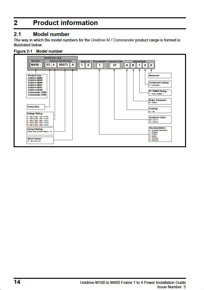
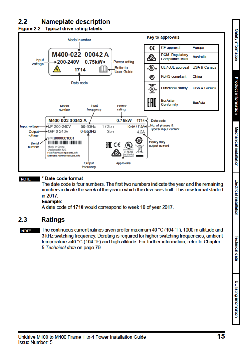

Table 2-1 100 V drive ratings (100 V to 120 V ±10 %)
Heavy Duty
Model
Input
phases
Maximum
continuous
output current
Open loop
peak current
RFC peak
current
Nominal power
at
200 V
Motor power
ph A A A kW hp
01100017
01100024 2.4 3.6 4.3 0.37 0.5
02100042 4.2 6.3 7.6 0.75 1
1
1.7 2.6 3.1 0.25 0.33
02100056 5.6 8.4 10.1 1.1 1.5
The 100 V drives have a voltage doubler circuit on the input, therefore the output voltage
is 200 V.
Table 2-2 200 V drive ratings (200 V to 240 V ±10 %)
Heavy Duty
Model
01200017 1 1.7 2.6 3.1 0.25 0.33
01200024 1 2.4 3.6 4.3 0.37 0.5
01200033 1 3.3 5 5.9 0.55 0.75
01200042 1 4.2 6.3 7.6 0.75 1
02200024 1/3 2.4 3.6 4.3 0.37 0.5
02200033 1/3 3.3 5 5.9 0.55 0.75
02200042 1/3 4.2 6.3 7.6 0.75 1
02200056 1/3 5.6 8.4 10.1 1.1 1
02200075 1/3 7.5 11.3 13.5 1.5 2
03200100 1/3 10 15 18 2.2 3
04200133 1/3 13.3 20 23.9 3 3
04200176 1 13.3 20 23.9 3 3
04200176 3 17.6 26.4 31.7 4 5
Input phases
ph A A A kW hp
Maximum
continuous
output current
Open loop
peak current
RFC peak
current
Nominal power
at 230 V
at 200 V
Motor power
at 230 V
16 Unidrive M100 to M400 Frame 1 to 4 Power Installation Guide
Issue Number: 5

Table 2-3 400 V drive ratings (380 V to 480 V ±10 %)
Heavy Duty
Model
02400013
02400018 1.8 2.7 3.2 0.55 0.75
02400023 2.3 3.5 4.1 0.75 1
02400032 3.2 4.8 5.8 1.1 1.5
02400041 4.1 6.2 7.4 1.5 2
03400056
03400073 7.3 11 13.1 3 3
03400094 9.4 14.1 16.9 4 5
04400135
04400170 17 25.5 30.6 7.5 10
Input phases
ph A A A kW hp
3
3
3
Maximum
continuous
output current
1.3 2 2.3 0.37 0.5
5.6 8.4 10.1 2.2 3
13.5 20.3 24.3 5.5 7.5
Open loop
peak current
R F C p e a k
current
Nominal
power at 400 V
Motor power
at 460 V
2.3.1 Typical short term overload limits
The maximum percentage overload limit changes depending on the selected motor. Variations in
motor rated current, motor power factor and motor leakage inductance all result in changes in the
maximum possible overload. The exact value for a specific motor can be calculated using the
equations detailed in Menu 4 in the Parameter Reference Guide.
Typical values are shown in the table below for RFC-A and open loop (OL) modes:
Table 2-4 Typical overload limits
Operating mode RFC From cold RFC From 100 %
Heavy Duty overload with motor
rated current = drive rated
current
180 % for 3 s 180 % for 3 s 150 % for 60 s 150 % for 8 s
Open loop from
cold
Open loop from
100 %
Safety information
Product information
Mechanical installation Electrical installation Technical data UL listing information
Generally the drive rated current is higher than the matching motor rated current allowing a higher
level of overload than the default setting.
The time allowed in the overload region is proportionally reduced at very low output frequency on
some drive ratings.
The maximum overload level which can be attained is independent of the speed.
Unidrive M100 to M400 Frame 1 to 4 Power Installation Guide 17
Issue Number: 5
2.4 Drive features
10
5
8
7
7
11
6
4
1
9
9
4
1
3
6
8
2
2
2
2
4
4
1
10
8
6
6
3
3
5
7
11
1
8
11
9
5
11
10
12
12
12
12
10
5
7
14
14
13
13
14
13
14
13
3
4
2
1
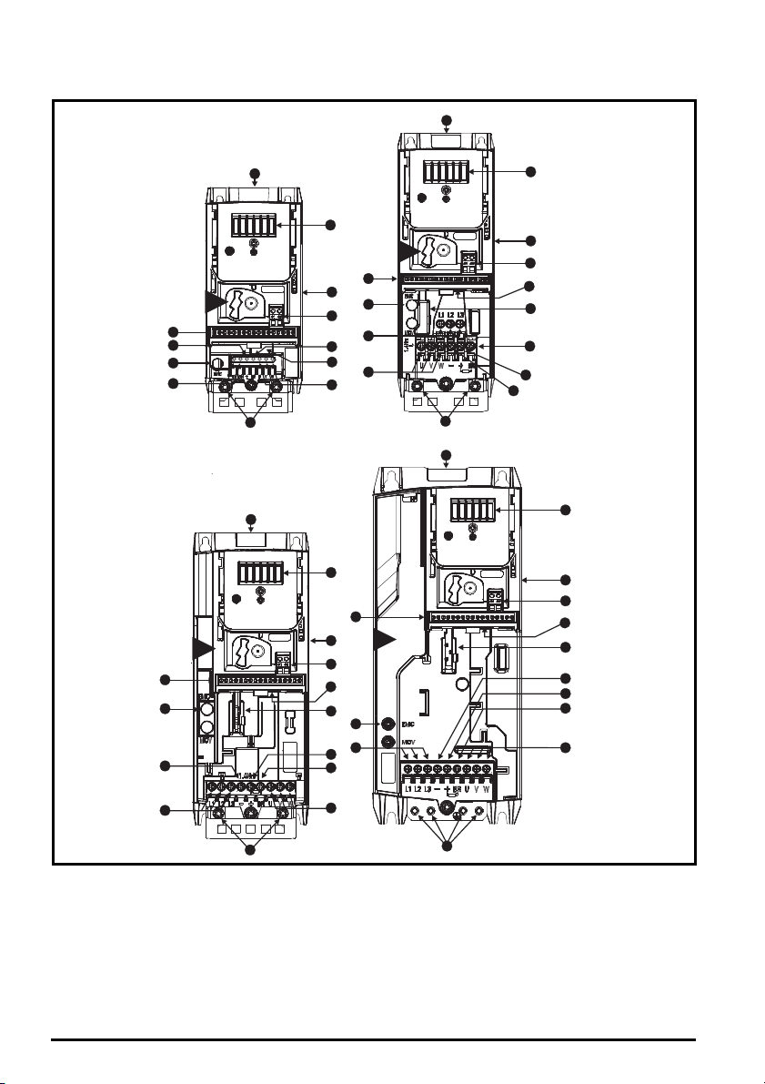
Figure 2-3 Features of the drive (Unidrive M400 illustrated)
Key
1. Rating label (On side of
drive)
2. Identification label 6. Braking terminal 10. Motor connections 14. Keypad connection
3. Option module
connection
4. Relay connections 8. DC bus + 12. Ground connections
5. Control connections 9. DC bus — 13. Safe Torque Off
7. Internal EMC filter
screw
11. AC supply connections
connections
18 Unidrive M100 to M400 Frame 1 to 4 Power Installation Guide
Issue Number: 5

3.2.2 Environmental protection
The drive must be protected from:
• Moisture, including dripping water or spraying water and condensation. An anti-condensation
heater may be required, which must be switched off when the drive is running.
• Contamination with electrically conductive material
• Contamination with any form of dust which may restrict the fan, or impair airflow over various
components
• Temperature beyond the specified operating and storage ranges
• Corrosive gasses
During installation it is recommended that the vents on the drive are covered to prevent
debris (e.g. wire off-cuts) from entering the drive.
3.2.3 Cooling
The heat produced by the drive must be removed without its specified operating temperature being
exceeded. Note that a sealed enclosure gives much reduced cooling compared with a ventilated one,
and may need to be larger and/or use internal air circulating fans.
For further information, refer to section 3.5.1 Enclosure sizing on page 28.
3.2.4 Electrical safety
The installation must be safe under normal and fault conditions. Electrical installation instructions are
given in Chapter 4 Electrical installation on page 41.
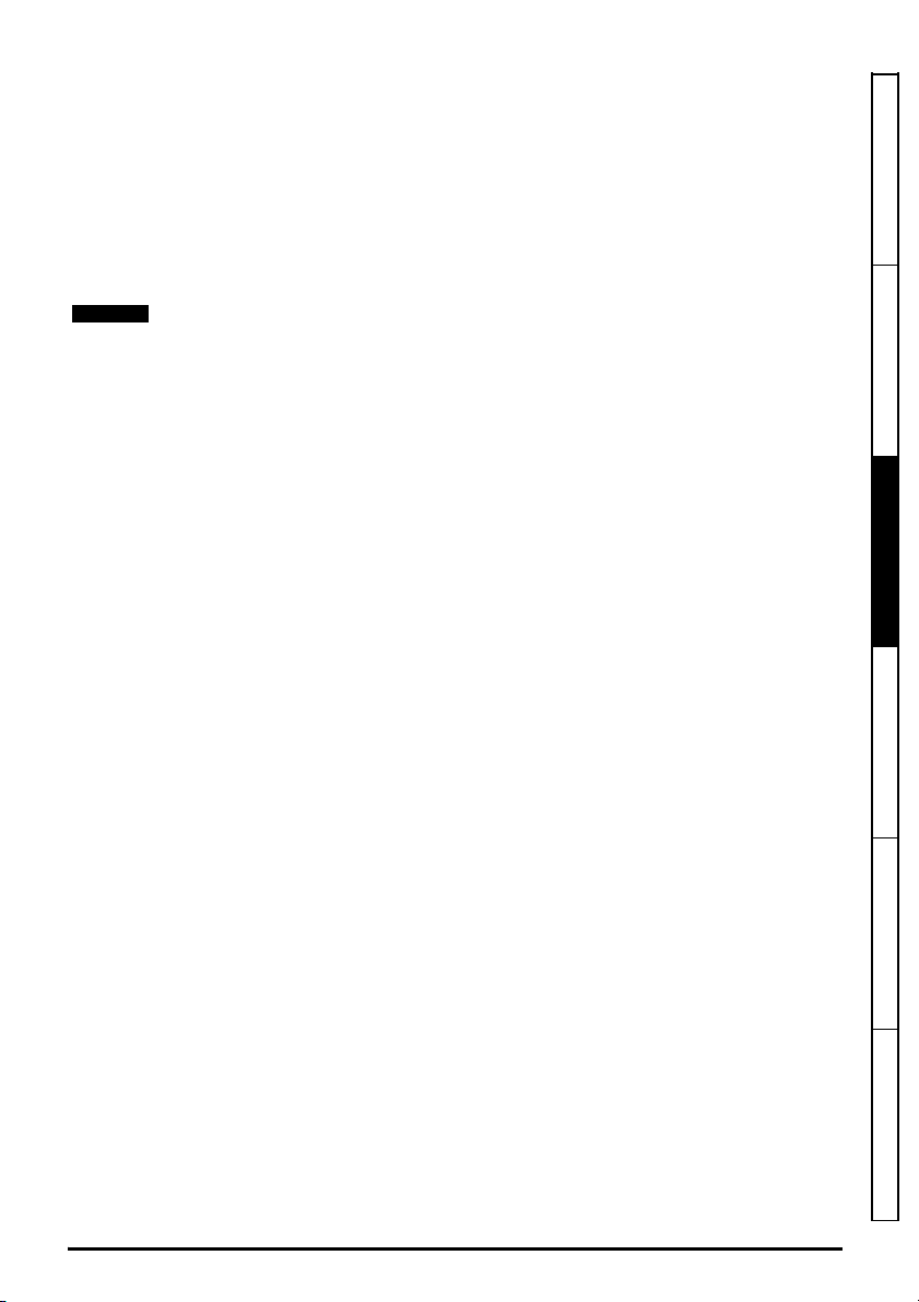
3.2.5 Fire protection
The drive enclosure is not classified as a fire enclosure. A separate fire enclosure must be provided.
For installation in the USA, a NEMA 12 enclosure is suitable.
For installation outside the USA, the following (based on IEC 62109-1, standard for PV inverters) is
recommended.
Enclosure can be metal and/or polymeric, polymer must meet requirements which can be
summarized for larger enclosures as using materials meeting at least UL 94 class 5VB at the point of
minimum thickness.
Air filter assemblies to be at least class V-2.
The location and size of the bottom shall cover the area shown in Figure 3-1. Any part of the side
which is within the area traced out by the 5° angle is also considered to be part of the bottom of the
fire enclosure.
Safety information Product information
Mechanical installation
Electrical installation Technical data UL listing information
Unidrive M100 to M400 Frame 1 to 4 Power Installation Guide 21
Issue Number: 5

3.5.1 Enclosure sizing
A
e
P
kT
intText
–
————————————
=
1. Add the dissipation figures from section 5.1.2 Power dissipation on page 81 for each drive that is
to be installed in the enclosure.
2. If an external EMC filter is to be used with each drive, add the dissipation figures from section
5.2.1 EMC filter ratings on page 101 for each external EMC filter that is to be installed in the
enclosure.
3. If the braking resistor is to be mounted inside the enclosure, add the average power figures for
each braking resistor that is to be installed in the enclosure.
4. Calculate the total heat dissipation (in Watts) of any other equipment to be installed in the
enclosure.
5. Add the heat dissipation figures obtained above. This gives a figure in Watts for the total heat that
will be dissipated inside the enclosure.
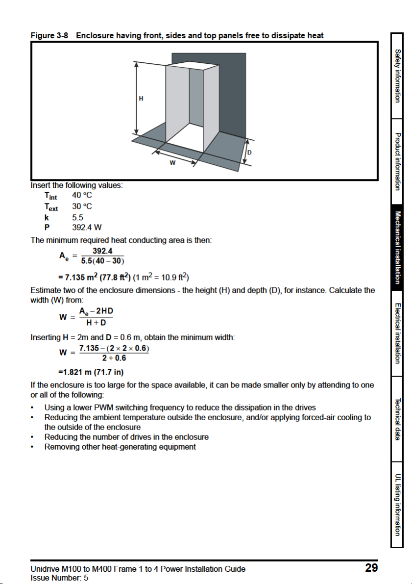
Calculating the size of a sealed enclosure
The enclosure transfers internally generated heat into the surrounding air by natural convection (or
external forced air flow); the greater the surface area of the enclosure walls, the better is the
dissipation capability. Only the surfaces of the enclosure that are unobstructed (not in contact with a
wall or floor) can dissipate heat.
Calculate the minimum required unobstructed surface area A
Where:
Unobstructed surface area in m2 (1 m2 = 10.9 ft2)
A
e
T
Maximum expected temperature in
ext
Maximum permissible temperature in oC inside the enclosure
T
int
o
C outside the enclosure
P Power in Watts dissipated by all heat sources in the enclosure
k Heat transmission coefficient of the enclosure material in W/m
Example
To calculate the size of an enclosure for the following:
• Two drives operating at the Normal Duty rating
• External EMC filter for each drive
• Braking resistors are to be mounted outside the enclosure
• Maximum ambient temperature inside the enclosure: 40 C
• Maximum ambient temperature outside the enclosure: 30 C
For example, if the power dissipation from each drive is 187 W and the power dissipation from each
external EMC filter is 9.2 W.
Total dissipation: 2 x (187 + 9.2) =392.4 W
for the enclosure from:
e
2/o
C
Power dissipation for the drives and the external EMC filters can be obtained from Chapter
5 Technical data on page 79.
The enclosure is to be made from painted 2 mm (0.079 in) sheet steel having a heat transmission
coefficient of 5.5 W/m
2/o
C. Only the top, front, and two sides of the enclosure are free to dissipate
heat.
The value of 5.5 W/m
2
/ºC can generally be used with a sheet steel enclosure (exact values can be
obtained from the supplier of the material). If in any doubt, allow for a greater margin in the
temperature rise.
28 Unidrive M100 to M400 Frame 1 to 4 Power Installation Guide
Issue Number: 5

Calculating the air-flow in a ventilated enclosure
V
3kP
T
intText
–
—————————
=
V
31.3 323.7
40 30–
—————————————
=
The dimensions of the enclosure are required only for accommodating the equipment. The
equipment is cooled by the forced air flow.
Calculate the minimum required volume of ventilating air from:
Where:
V Air-flow in m
T
Maximum expected temperature in C outside the enclosure
ext
T
Maximum permissible temperature in C inside the enclosure
int
3
per hour (1 m3/hr = 0.59 ft3/min)
P Power in Watts dissipated by all heat sources in the enclosure
k Ratio of
Where:
P
is the air pressure at sea level
0
is the air pressure at the installation
P
I
Typically use a factor of 1.2 to 1.3, to allow also for pressure-drops in dirty air-filters.
Example
To calculate the size of an enclosure for the following:
• Three drives operating at the Normal Duty rating
• External EMC filter for each drive
• Braking resistors are to be mounted outside the enclosure
• Maximum ambient temperature inside the enclosure: 40 C
• Maximum ambient temperature outside the enclosure: 30 C
For example, dissipation of each drive: 101 W and dissipation of each external EMC filter: 6.9 W
(max).
Total dissipation: 3 x (101 + 6.9) = 323.7 W
Insert the following values:
T
40 C
int
T
30 C
ext
k 1.3
P 323.7 W
Then:
= 126.2 m
30 Unidrive M100 to M400 Frame 1 to 4 Power Installation Guide
3
/hr (74.5 ft3 /min) (1 m3/ hr = 0.59 ft3/min)
Issue Number: 5
Loading…
Изображения служат только для ознакомления,
см. техническую документацию
Drive Type
Variable Speed
Все параметры
1 шт.
на сумму 108 700 руб.
Плати частями
от 27 175 руб. × 4 платежа
Описание
The new Commander C series has been designed to be a simple and compact AC motor speed controller that meets advanced requirements in a wide range of applications and provides optimum user experience.
Технические параметры
| Control Panel | Yes |
| Current Rating | 4.2 A |
| Drive Type | Variable Speed |
| For Use With | AC Motors |
| Function | Motor Control |
| IP Rating | IP20 |
| Mounting Type | Panel Mount |
| Output Frequency | 0 → 550Hz |
| Overall Width | 130mm |
| Phase | 1 |
| Power Rating | 0.75 kW |
| Series | C200 |
| Supply Voltage | 200 → 240 V ac |
| Вес, кг | 1.04 |
Техническая документация
Сроки доставки
Доставка в регион Сальск
| ПВЗ СДЭК | ||
| ПВЗ 5Post | ||
| Курьер | 9 июля1 | 362 руб.2 |
| ПВЗ Почта России | 9 июля1 | 426 руб.2 |
Цена и наличие в магазинах
| Ростов-на-Дону, проспект Соколо́ва, 53/182 |
нет в наличии |