
SERIE Z |
SCHEDA COMANDO
CONTROL BOARD
TARJETA DE MANDO
Z
SERIES
/
SERIE Z
ZBX7
Documentazione
Tecnica
S19
/ ESPAÑOL
rev. 2.1
11/2005
©
ENGLISH
CANCELLI
AUTOMATICI
ITALIANO/
319S19-1
CAME
ITALIANO—ENGLISH—ESPAÑOL
ITALIANO
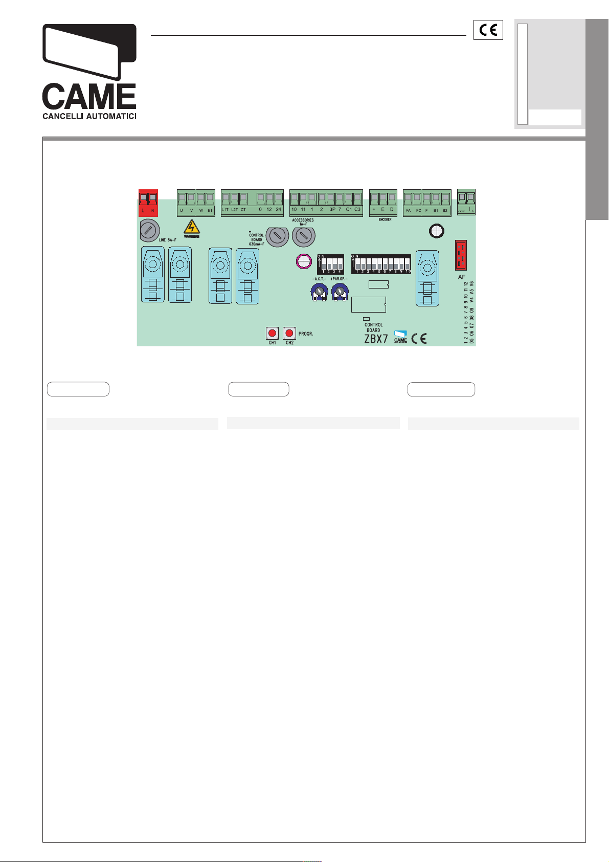
CARATTERISTICHE GENERALI
Descrizione scheda
La scheda comando ZBX7 è adatta al
comando di automazioni scorrevoli
alimentati a 230V monofase della serie BX-A/BX-B.
La scheda va inserita e fissata nel
contenitore porta-schede del motoriduttore (vedi descrizione montaggio
a pag.12), ed alimentata con una tensione di 230V(a.c.) nei morsetti
L1 e L2.
É protetta in ingresso con due fusibili da 5A, mentre i dispositivi di comando a bassa tensione (24V) sono
protetti con fusibile da 1A.
La potenza complessiva degli accessori (24V) non deve superare i 20W.
ENGLISH
GENERAL CHARACTERISTICS
Description of control panel
The ZBX7 control board is used as a
remote control for BX-A/BX-B series
230V single-phase automated sliding
gates.
The board is introduced and fixed in
place in the gearmotor’s circuit board
holder (see assembly description on
page 12), at 230V (a.c.) in terminals
L1 and L2.
The inlet is protected with two 5A fuses,
while the low voltage (24V) control devices are protected with a 1A fuse.
The accessorie’s total capacity (24V)
should not exceed 20W.
ESPANOL
CARACTERISTICAS GENERALES
Descripciön cuadro de mando
La tarjeta de mando ZBX7 es idónea
para el accionamiento de automatizaciones de puertas correderas alimentadas a 230V monofásica de la
serie BX-A/BX-B.
La tarjeta se introduce y fija en la caja
respectiva en el motorreductor (véase descripción montaje en pág.12), y
se alimenta con una tensión de 230V
(c.a.) en los bornes L1 y L2.
La tarjeta está protegida en la entrada
por dos fusibles de 5A, mientras que
los dispositivos de accionamiento de
baja tensión (24V) están protegidos
por fusible de 1A.
La potencia total de los accesorios
(24V) no tiene que superar los 20W.

Sicurezza
Le fotocellule possono essere col-
legate e predisposte per:
Riapertura
C1), le fotocellule rilevando un ostacolo durante la fase di chiusura del
cancello, provocano l’inversione di
marcia fino alla completa apertura;
—
Stop parziale,
se in movimento con conseguente
pre disposizione alla chiusura automatica (2-C3);
—
Stop totale
lo con l’esclusione del ciclo di chiusura automatica, per riprendere il
ITALIANO—ENGLISH—ESPAÑOL
movimento del cancello, agire sulla
pulsantiera o sul radiocomando;
in fase di chiusura (2-
arresto del cancello
(1-2), arresto del cancel-
Safety
Photocells can be connected to ob-
tain:
—
Re-opening during closure (2-C1), if
the photocells identify an obstacle while
the gate is closing, they will reverse
the direction of movement until the gate
is completely open;
—
Partial stop, shutdown of moving gate,
with activation of an automatic closing
cycle (2-C3);
—
Total stop (1-2), shutdown of gate
movement without automatic closing;
a pushbutton or radio remote control
must be actuated to resume movement).
Seguridad
Il est possible de brancher des photocellules et de les programmer pour:
—
Réouverture
(2-C1), les cellules photoélectriques
provoquent l’inversion de marche
jusqu’à l’ouverture complète si elles
relèvent un obstacle durant la phase
de fermeture du portail;
—
Parada parcial,
si se encuentra en movimiento con
la consiguiente predisposición al
cierre automático (2-C3);
—
Parada total
ta excluyendo el posible ciclo de cierre automático, para reactivar el movimiento es preciso actuar en el teclado o en el mando a distancia;
en phase de fermeture
parada de la puerta
(1-2), parada de la puer-
Nota: Se un contatto di sicurezza
normalmente chiuso (2-C1, 2-C3, 1-
2) si apre, viene segnalato dal
lampeggio del LED di segnalazione (pag.14 — n°10);
—
Rilevazione di presenza ostacolo.
A motore fermo (cancello chiuso,
aperto o dopo un comando di stop
totale), impedisce qualsiasi movimento se i dispositivi di sicurezza
(es. fotocellule) rilevano un ostacolo;
Accessori collegabili
—
Lettore ottico art.001B4336
gli ostacoli durante i movimenti del
cancello, nella fase di apertura il
cancello si ferma e riprende il movimento di chiusura dopo il conteggio
della chiusura automatica, mentre
in chiusura inverte il senso di marcia.
, rileva
N.B: If an NC safety contact (2-C1, 2-
C3, 1-2) is opened, the LED
(pag.14 -n°10) will flash to indicate this
fact;
-Obstacle presencedetection. When the
motor is stopped (gate is closed, open
or half-open after an em ercency stop
command), the transmitter and the control pushbutton will be deactiv ated if an
obstacle is detected by one of the
safety devices (for example, the photocells);
Accessories which can be
connected to this unit
—
Item. 001B4336 optical reader, detects obstacles during the gate’s
movement; during the opening phase,
the gate stops and then begins a closing movement after the automatic
closure count, whilst during closure the
direction of movement is inverted.
Nota
: La apertura de un contacto de
seguridad normalmente cerrado (2C1, 2-C3, 1-2) es señalada por medio
del destello LED de señalización
(pàg. 14 — n° 10).
-Detección de presencia obstàculo.
Con el motor parado (puerta cerrada, abierta o en posición semi-abierta
obtenida a través de un comando de
stop total), anula cualquier función
del transmisor o del botòn en caso
de obstàculo detectado por los dispositivos de seguridad (por ejemplo: fotocélulas).
Accesorios conectables
—
Lector óptico art. 001B4336
los obstáculos durante los movimientos de la puerta; durante la apertura
la puerta se detiene e inicia el movimiento de cierre, después de la cuenta
del cierre automático; mientras, que
durante el cierre, invierte la dirección del movimiento.
, detecta
Attenzione! Nella fase di chiusura,
dopo tre rilevamenti consecutivi, il
cancello si fer ma in apertura e viene
esclusa la chiusura automatica, per
riprendere il movimento del cancello, agire sulla pulsantiera o sul
radiocomando;
-2-
Warning: during closure, if obstacles
are detected three times consecutively, the gate will remain open and
automatic closure will be discontinued.
To resume the gate’s movement, use
the push-button panel or the remote
control;
Atención: durante el cierre, tras tres
detecciones consecutivas, la puerta
se detiene en el movimiento de apertura y se desconecta el cierre
automático, para reactivar el movimiento de la puerta, use el pulsador
o el radiocontrol;

—
Lampada ciclo
. Lampada che illumina la zona di manovra, rimane
accesa dal momento in cui le ante
iniziano l ’apertura fino alla completa chiusura (compre so il tempo di
chiusura automatica). Nel caso non
viene inserita la chiusura automatica, rimane accesa solo durante il
movimento. La funzione della lampada ciclo se i dip n°1 “chiusura
automati ca” e n°6 “rilevazione presenza ostacolo” sono posizioni in
ON, vedi pagina 16.
— Cycle lamp. The lamp which lights the
manoeuvring zone: it remains lit from
the moment the doors begin to open
until they are completely closed (including the time required for the
automatic closure). In case automatic
closure is not enabled, the lamp remains lit only during movement.
The function of the cycle lamp is obtained in output W-E1 only if dip switch
numbers: 1 “automatic closing” and No.
6 “detect obstacle presence” are set to
ON (see page 16).
— Lámpara ciclo. Lámpara que alumbra la zona de maniobra: se queda
encendida a partir del momento en
que las hojas empiezan la apertura
hasta el cierre completo (incluyendo
el tiempo de cierre automático). Si
no se habilita el cierre automático, el
cierre permanece encendido sólo durante el movimiento.
El funcionamiento de la lámpara ciclo se obtiene en la salida W-E1 sólo
si los dips n°1 “cierre automático” y
n°6 “detección presencia obstáculo”
están colocados en ON, véase
página 16.
ITALIANO—ENGLISH—ESPAÑOL
Altre funzioni
—
Chiusura automatica.
Il temporizzatore di chiusura automatica si autoalimenta a finecorsa in apertura. Il
tempo prefissato regolabile, è in ogni
modo subordinato dall’intervento di
eventuali accessori di sicurezza e si
esclude dopo un intervento di «stop»
o in mancanza d’energia elettrica.
—
Apertura parziale
. Apertura del cancello per passaggio pedonale, viene
attivata collegandosi ai morsetti 23P ed è regolabile mediante trimmer
AP.PARZ.. Con questa funzione, la
chiusura automatica varia nel seguente modo:
1) Dip 1 in ON «chiusura automatica
attivata».
— Dopo un’apertura parziale, il tempo di chiusura è dipendente dalla
regolazione del trimmer TCA.
2) Dip 1 in OFF «chiusura automatica disattivata».
— Se il trimmer del TCA è regolato al
minimo, dopo un’apertura parziale
non parte il conteggio di chiusura
automatica.;
— Se il trimmer del TCA è regolato al
massimo, dopo un ‘apertura parziale, il tempo di chiusura è fisso a 8
secondi.
—
«Uomo presente»
. Funzionamento
del cancello mantenendo premuto il
pulsante (esclude la funzione del
radiocomando);
—
Rallentamento a finecorsa.
FUNZIONE DISPONIBILE SOLO PER CANCELLI
CON
PESO MASSIMO DI 300 KG, ALTRIMENTI
DEVE ESSERE DISATTIVATA
Other functions
—
Automatic closing.
The
automatic closing timer is automatically activated at
the end of the opening cycle. The preset, adjustable automatic closing time
is automatically interrupted by the activation of any safety system, and is
deactivated after a STOP command or
in case of power failure;
—
Partial opening. Gate opening for passage on foot is activated by connecting to the 2-3P terminal blocks and it
can be adjusted by the AP.PARZ. trimmer. By using this function, automatic
closure varies as follows:
1) Dip 1 ON — Automatic closure activated.
-after a partial opening, the closure time
does depend on any adjustment of the
TCA trimmer.
2) Dip 1 OFF — Automatic closure deactivated.
— If the TCA trimmer is set to the min-
imum, after a partial opening, automatic closure counting does not begin;
— If the TCA trimmer is set to the max-
imum, after a partial opening, closing
time is set to 8 seconds.
—
«Operator present». Gate operates
only when the pushbutton is held down
(the radio remote control system is
deactivated);
—
Slowing at the limit switch.
FUNCTION AVAIABLE ONLY FOR GATES WEIGH
ING UP TO
DISACTIVATED
300 KG,
OTHERWISE IT MUST BE
—
Otras funciones
—
Cierre automático
. El temporizador
de cierre automático se autoalimenta en fin-de-tiempo carrera en fase
de apertura. El tiempo prefijado regulable, sin embargo, está subordinado a la intervención de posibles
accesorios de seguridad y se excluye después de una intervención de
parada o en caso de falta de energía
eléctrica;
—
Apertura parcial
. La apertura de la
verja para el paso peatonal, se activa conectado los bprnes 2-3P y puede ser regulada por medio del trimmer AP.PARZ.;
Con esta función, el cierre automático se modifica de la siguiente manera:
1) Dip 1 en ON «cierre automático
activo».
— Tras una apertura parcial, el tiempo de cierre es dependiente de la regulación del trimmer TCA.
2) Dip 1 en OFF «cierre automático
desactivado».
-Si el trimmer del TCA está regulado al mínimo, tras una apertura parcial no se acciona la cuenta de cierre automático;
— Si el trimmer del TCA está regulado al máximo, tras una apertura parcial, el tiempo de cierre queda fijo
en 8″.
—
Función a «hombre presente»
. Funcionamiento de la puerta manteniendo pulsada la tecla (excluye la función del mando a distancia);
-Desaceleraciòn en final de carrera.
FUNCIÓN DISPONIBLE SÓLO PARA
CANCELAS
EN CASO CONTRARIO DEBE SER
DESACTIVADA
CON 300 KG DE PESO MÁXIMO,
-3-
Il cancello rallenta la corsa prima
della completa apertura o chiusura.
Funziona solo con lettore ottico inserito.
Dopo ogni chiusura e apertura dello
sportellino di sicurezza o dopo un
ripristino della tensione, la funzione
di rallentamento è attiva dal 2° comando in poi.
—
Prelampeggio
di apertura o di chiu sura, il lampeggiatore collegato su W-E1, lampeggia per 5 secondi prima di iniziare la
manovra.
ITALIANO—ENGLISH—ESPAÑOL
— Comando di chiusura.
sola chiusura del can cello, con dispositivo di co mando collegato sul
contatto 2-7, posizionare il dip 1 in
ON (modulo a 4 vie), vedi pagina 22;
— Comando di apertura.
sola apertura del cancello, con dispositivo collegato sul contatto 23P, posizionare il dip 2 in ON (modulo a 4 vie), vedi pagina 22;
-Tipo di comando
-apre-stop-chiude-stop con pulsante e/o trasmettitore;
-apre-chiude con pulsante e/o trasmettitore;
-solo apre per trasmettitore.
Regolazioni
— Tempo chiusura automatica;
— Tempo di apertura parziale.
. Dopo un co mando
Funzione di
Funzione di
:
The gate slow down before the opening
or closing movement is completed.
Only works with the optical reader on.
After every opening and closing of the
safety door or after restoring the voltage, the slowing function is active from
nd
the 2
command onwards.
Pre-flashing. After an opening or clos-
ing command, the flasher connected to
the W-E1 flashes for 5 seconds before
beginning the procedure;
—
Closing command. Function of closing the gate only, with a wire less
control device connected to contact
2-7, set dip 1 to ON (4- way module),
see page 22;
—
Opening command. Function of opening the gate only, with a wireless control
device connect ed to contact 2-3P, set
dip 2 to ON (4-way module), see page 22;
—
Type of command:
-Open-stop-close-stop by button and
transmitter;
-Open-close by button and transmitter;
-Open only by transmitter.
Adjiustments
— Automatic closure time;
— Partial opening time.
La puerta desacelera la carrera antes
de completar la apertura o el cierre.
Funciona sólo con lector óptico conectado.
Tras cada apertura o cierre de la tapa
de seguridad, o tras una reactivación de la tensión, la función de
desaceleración está activa desde el
2° mando en adelante.
—
Intermitencia
do de apertura o cierre, la lámpara
intermitente conectada en W-E1, parpadea por 5 segundos antes de comenzar la maniobra;
— Mando de cierre.
cierre de la puerta, con dispositivo
de mando conectado en el contacto
2-7, coloque el dip 1 en ON (módulo
de 4 vías), véase página 22;
— Mando de apertura.
de apertura de la puerta, con dispositivo de mando conectado en el
contacto 2-3P, coloque el dip 2 en
ON (módulo de 4 vías), véase página
22;
-Tipo de mando
-abrir-stop-cerrar-stop para botón y
transmisor;
-abrir-cerrar para botón y transmisor;
-sólo apertura para transmisor.
Regulaciones
— Tiempo de cierre automático;
— Tiempo de apertura parcial.
. Después de un man-
Función sólo de
Función sólo
:
ATTENZIONE: prima di intervenire all’interno dell’apparecchiatura, togliere la tensione di linea
-4-
IMPORTANT: Shut off the mains
power before servicing the inside
of the unit.
ATENCION: antes de actuar dentro del aparado, quitar la tensión de línea
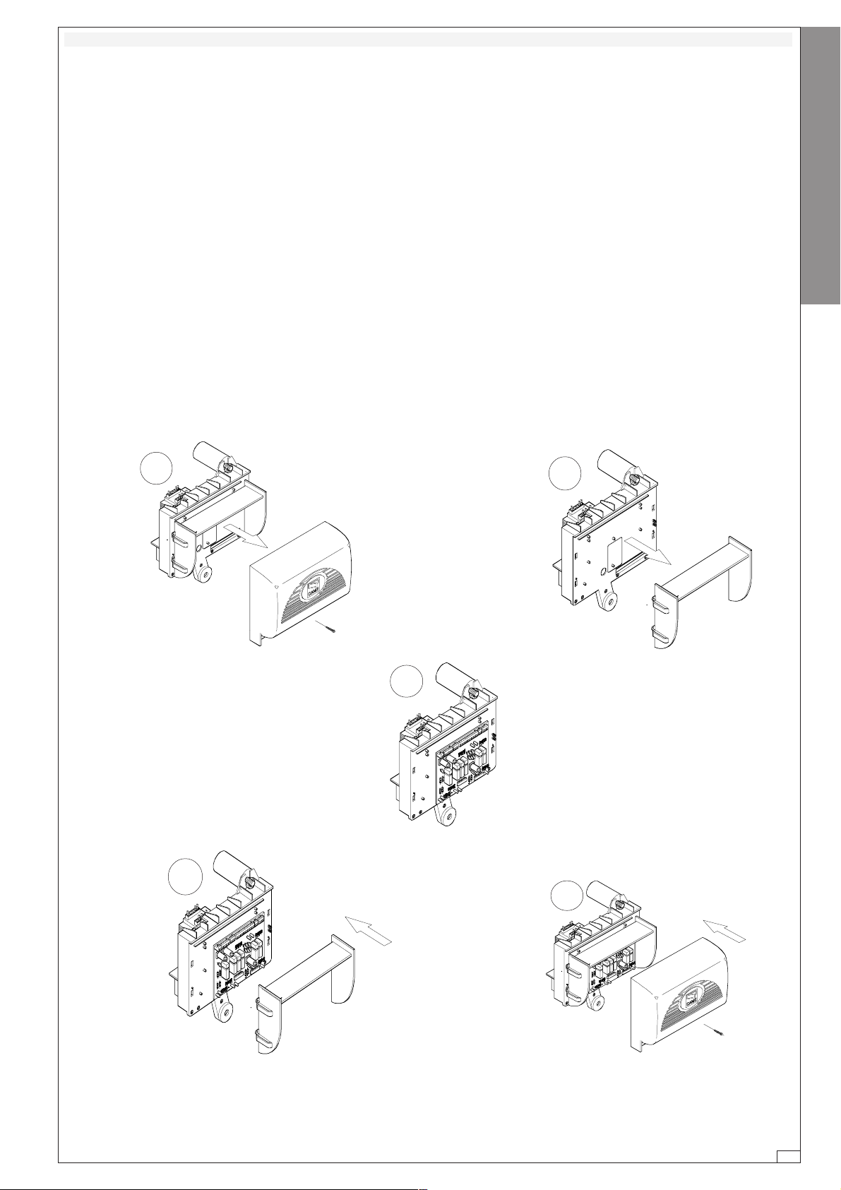
DESCRIZIONE DI MONTAGGIO —
ASSEMBLY DESCRIPTION
— DESCRIPTIÓN DEL MONTAJE
-Aprire lo sportello accesso sblocco,
allentare la vite del coperchio quadro
comando e levarlo (1).
-Rimuovere il copri-scheda dalla piastra di supporto quadro comando
(2).
-Agganciare e fissare la scheda ZBX7
nella piastra di supporto quadro comando con le viti predisposte (3).
-Riposizionare il supporto coprischede (4).
-Procedere al collegamento elettrico, fissare il coperchio del quadro
comando e chiudere lo sportello accesso blocco (5).
1
-Open the release access door, loosen
the screws of the control panel cover
and lift it (1).
-Remove the circuit board cover from
the control panel support plate (2).
-Hook and fix the ZBX7 board to the
control panel support plate with the
appropriate screws (3).
-Reposition the circuit board cover support (4).
-Proceed with the electric connection,
replace the control panel cover and
close the release access door (5).
-Abra la puerta de acceso al desbloqueo, afloje el tornillo de la tapa del
cuadro de mando y quítelo (1).
-Quite el cubretarjeta de la placa de
soporte del cuadro de mando (2).
-Enganche y fije la tarjeta ZBX7 a la
placa de soporte del cuadro de mando, con los tornillos suministrados
(3).
-Vuelva a colocar el soporte cubretaryeta (4).
-Realice la conexión eléctrica, fije la
tapa del cuadro de mando y cierre la
puerta de acceso al desbloqueo (5).
2
ITALIANO—ENGLISH—ESPAÑOL
3
4
5
-5-
ITALIANO—ENGLISH—ESPAÑOL
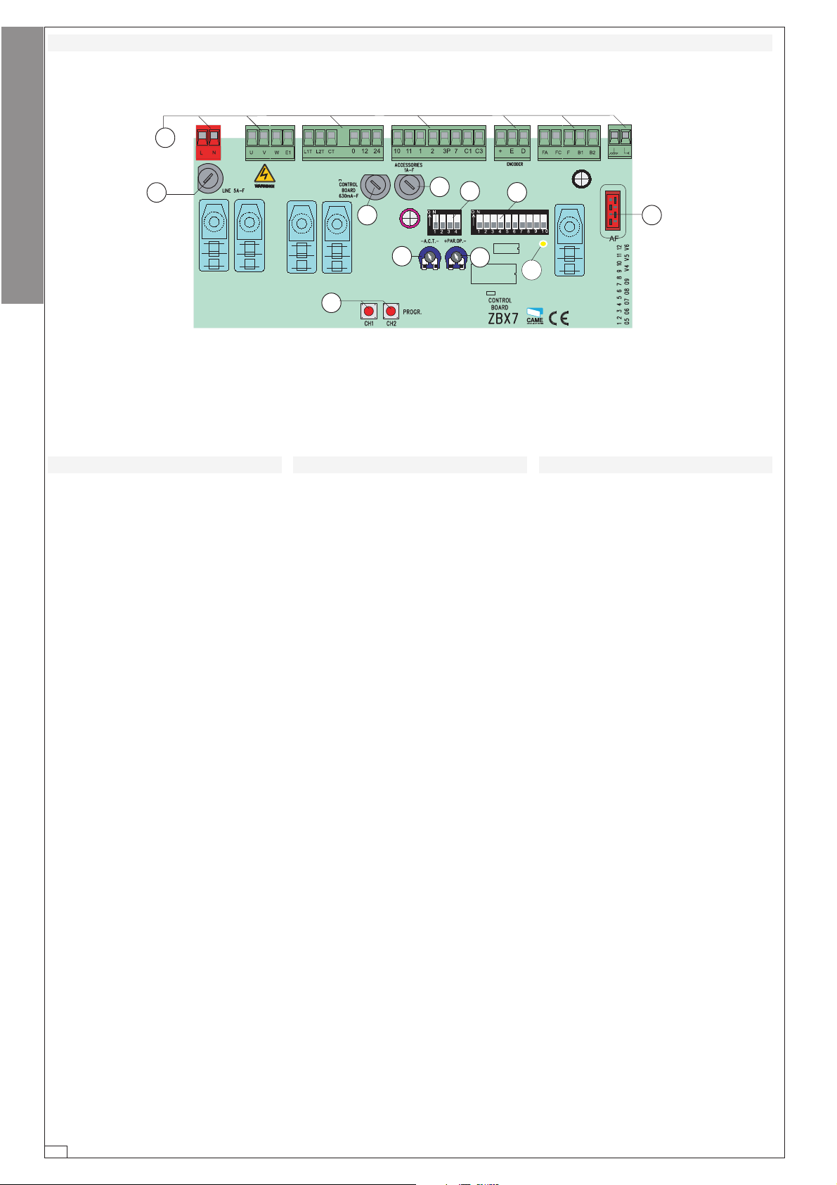
SCHEDA BASE —
11
1
11
22
2
22
MOTHERBOARD
44
4
44
77
7
77
55
5
55
— TARJETA BASE
33
3
33
88
8
88
66
6
66
99
9
99
1010
10
1010
1111
11
1111
COMPONENTI PRINCIPALI
1 Morsettiere di collegamento
2 Fusibili di linea 5A
3 Fusibile accessori 1A
4 Fusibile scheda 630 mA
5 Pulsanti di memorizzazione co-
dice radio
6 Trimmer di regolazione apertura
parziale
7 Trimmer di regolazione tempo di
chiusura automatica
8 Selettore funzioni a 4 dip (vedi
pag.22)
9 Selettore funzioni a 10 dip (vedi
pag.19)
10 Innesto scheda radiofrequenza
(vedi tabella)
11 LED segnalazione
MAIN COMPONENTES
1
Terminal block for external conections
2 Line fuse, 5A
3 Fuse on accessory power line, 1A
4 Fuse Control Board 630 mA
5 Radio-code save buttons
6 Trimmer for adjustment operating
time
7 Trimmer for adjustment automatic
closing
8 4-dip function switch (see pag.22)
9 10-dip function switch (see pag.19)
10Socket AF radiofrequency board (see
table)
11Signal LED
PRINCIPALES COMPONENTES
1 Caja de bornes para las conexió-
nes
2 Fusible de línea 5A
3 Fusible accesorios 1A
4 Fusible ficha de control 630 mA
5 Teclas de memorización del códi-
go radio
6 Trimmer de regulación tiempo tra-
bajo
7 Trimmer de regulación tiempo cie-
rre automático
8 Selector de funciones con 4 dip
(vedas pág.22)
9 Selector de funciones con 10 dip
(vedas pág.19)
10Conexión tarjeta radiofrecuencia
AF (vedas tabla)
11LED de señal
-6-
Loading…
В данном документе собраны все инструкции по блокам управления автоматикой ворот CAME. Здесь представлены инструкции только для плат и блоков управления автоматикой ворот для удобства поиска нужных документов. Для просмотры других инструкций по автоматике ворот смотрите похожие статьи.
Похожие статьи
Инструкции автоматика CAME
В данном документе собраны все инструкции по автоматике ворот CAME, а также по всему дополнительному оборудованию. Инструкции на приводы откатных, распашных и гаражных ворот, системы безопасности (фот..
Инструкции приводы распашных ворот CAME
В данном документе собраны все инструкции по приводам распашных ворот CAME. Здесь представлены инструкции только на приводы распашных ворот для удобства поиска нужных документов. Для просмо..
Инструкции приводы откатных ворот CAME
В данном документе собраны все инструкции по приводам откатных ворот CAME. Здесь представлены инструкции только на приводы откатных ворот для удобства поиска нужных документов. Для просмотры других ин..
Инструкции приводы гаражных ворот CAME
В данном документе собраны все инструкции по приводам секционных гаражных ворот CAME. Здесь представлены инструкции только на приводы гаражных ворот для удобства поиска нужных документов. Для просмотр..
Инструкции приводы промышленных ворот CAME
В данном документе собраны все инструкции по приводам промышленных секционных ворот CAME. Здесь представлены инструкции только на приводы промышленных ворот для удобства поиска нужных документов. Для ..
- Home
- Инструкции
- Автоматика для ворот
- CAME
- ZBX7
| CAME ZBX7 инструкция | |
|---|---|
| Тип инструкции: | Руководство по установке и использованию |
| Категория: | Автоматика для ворот CAME |
| Язык: | Русский |
| Размер: | 1 Mb |
| Формат файла: | |
| Дата добавления: | 06.08.2013 |
Похожие записи
CAME ZBX7 — Схема электрическая принципиальная
Автоматика для ворот
CAME BK-BKE 2210 — Инструкция по монтажу
Автоматика для ворот
CAME DADOO — Инструкция по монтажу
Автоматика для ворот
CAME DBS 02 — Инструкция по монтажу
Автоматика для ворот
CAME DELTA-SE — Инструкция по монтажу
Автоматика для ворот
CAME FROG A — Инструкция по монтажу
Автоматика для ворот
CAME G0460 — Инструкция по монтажу
Автоматика для ворот
CAME GARD G4040IZ — Инструкция по монтажу
Автоматика для ворот
Комментарии, вопросы, отзывы
Напишите свои комментарии к материалу, вопросы или отзывы по оборудованию
Ответить 03.01.2020 17:19
Vladimir
Схема Блока управления»CAME ZBX7″ необходима для подключения дополнительных функций.
Кто вы? человек робот
FAQ: Types of Manuals and Their Contents
CAME ZBX7 Manuals come in various types, each serving a specific purpose to help users effectively operate and maintain their devices. Here are the common types of CAME ZBX7 User Guides and the information they typically include:
- User Manuals: Provide comprehensive instructions on how to use the device, including setup, features, and operation. They often include troubleshooting tips, safety information, and maintenance guidelines.
- Service Instructions: Designed for technicians and repair professionals, these manuals offer detailed information on diagnosing and repairing issues with the device. They include schematics, parts lists, and step-by-step repair procedures.
- Installation Guides: Focus on the installation process of the device, providing detailed instructions and diagrams for proper setup. They are essential for ensuring the device is installed correctly and safely.
- Maintenance Manuals: Provide guidance on routine maintenance tasks to keep the device in optimal condition. They cover cleaning procedures, part replacements, and regular servicing tips.
- Quick Start Guides: Offer a concise overview of the essential steps needed to get the device up and running quickly. They are ideal for users who need immediate assistance with basic setup and operation.
Each type of CAME ZBX7 instruction is designed to address specific needs, ensuring users have the necessary information to use, maintain, and repair their devices effectively.
Related Instructions for CAME ZBX7:
6
EMEGA E306
Manual #59J95X: EMEGA E306 Garage Door Opener Manual
40
1239
211
Control Unit Devices by Other Brands:
|
FARFISA INTERCOMS PL10PED Manual FARFISA INTERCOMS Control Unit Manual (File: farfisa-intercoms-pl10ped-manual-2, 16.01.2025) Art. PL10PED, PL11PED, PL12PED 16 Jan 2025 | 2 |
|
|
UTEPO SFP-1.25G-550M Quick Start Manual PDF Manual (@JEMJ1N), UTEPO SFP-1.25G-550M Control Unit (20/02/2025) Please follow the installation step 20 Feb 2025 | 2 |
|
|
Nibe PCS 44 Installer Manual #NZB9U4: PCS 44 Heat Pump Installer manual Installatörshandbok 11 Feb 2025 | 76 |
|
|
Bitzer CM-RC-01 Maintenance Instructions Manual User Manual: Bitzer CM-RC-01 (644VV5, Upd.29th Nov 2024) KW-233-2 29 Nov 2024 | 39 |
Categories:
Touch terminals
IP Access Controllers
Recording Equipment
Touchscreen
I/O Systems
Switch
since 1993
Документация
По категориям
По названию товара
По брендам
Как найти нужную документацию?
Найти нужную документацию можно тремя способами:
- Воспользоваться поиском по категории. Структура категорий полностью повторяет структуру каталога, так что если вы точно знаете, где находится нужный товар, или примерно понимаете, где он может находиться, но не помните его название и торговую марку, этот способ, вероятно, будет самым удобным.
- Воспользоваться поиском по названию товара. Этот способ подойдёт, если вы хотя бы примерно знаете как товар называется или знаете его артикул.
- Воспользоваться поиском по брендам. Этот вариант подойдёт, если известна только торговая марка товара, или нужна вся доступная документация по конкретному бренду.
Установка, подключение и программирование блока управления ZBX7
Установка, подключение и программирование блока управления ZBX7