
View the manual for the Asrock B560M Steel Legend here, for free. This user manual comes under the category motherboards and has been rated by 1 people with an average of a 6.9. This manual is available in the following languages: English. Do you have a question about the Asrock B560M Steel Legend?
Ask your question here
Asrock B560M Steel Legend specifications
Below you will find the product specifications and the manual specifications of the Asrock B560M Steel Legend.
Processor manufacturer
Intel
Supported storage drive interfaces
M.2, SATA III
Parallel processing technology support
—
General
| Brand | Asrock |
| Model | B560M Steel Legend | 90-MXBFA0-A0UAYZ |
| Product | motherboard |
| EAN | 4710483934179 |
| Language | English |
| Filetype | User manual (PDF) |
Processor
| Processor manufacturer | Intel |
| Processor socket | LGA 1200 (Socket H5) |
| Compatible processor series | Intel Celeron, Intel Core i3, Intel Core i5, Intel Core i7, Intel Core i9, Intel Pentium |
| Maximum number of SMP processors | 1 |
Memory
| Number of memory slots | 4 |
| Memory slots type | DIMM |
| Maximum internal memory | 128 GB |
| Supported memory clock speeds | 4666,4800 MHz |
| Unbuffered memory | Yes |
| Memory channels | Dual-channel |
| Supported memory types | DDR4-SDRAM |
Storage controllers
| Supported storage drive interfaces | M.2, SATA III |
Graphics
| Parallel processing technology support | — |
Internal I/O
| USB 2.0 connectors | 2 |
| USB 3.2 Gen 1 (3.1 Gen 1) connectors | 1 |
| USB 3.2 Gen 2 (3.1 Gen 2) connectors | 1 |
| Number of SATA III connectors | 6 |
| Number of SATA II connectors | 0 |
| Number of Parallel ATA connectors | — |
| CPU fan connector | Yes |
| ATX Power connector (24-pin) | Yes |
| EPS power connector (8-pin) | Yes |
| Front panel audio connector | Yes |
| TPM connector | Yes |
| RGB LED pin header | Yes |
Rear panel I/O ports
| USB 2.0 ports quantity | 2 |
| USB 3.2 Gen 1 (3.1 Gen 1) Type-A ports quantity | 4 |
| USB 3.2 Gen 1 (3.1 Gen 1) Type-C ports quantity | 0 |
| USB 3.2 Gen 2 (3.1 Gen 2) Type-A ports quantity | 0 |
| USB 3.2 Gen 2 (3.1 Gen 2) Type-C ports quantity | 0 |
| Ethernet LAN (RJ-45) ports | 1 |
| eSATA ports quantity | 0 |
| PS/2 ports quantity | 1 |
| Firewire (IEEE 1394) ports | 0 |
| VGA (D-Sub) ports quantity | 0 |
| HDMI ports quantity | 1 |
| DVI-D ports quantity | 0 |
| DisplayPorts quantity | 1 |
| DisplayPort version | 1.4 |
| S/PDIF out port | Yes |
Network
| Ethernet LAN | Yes |
| Ethernet interface type | 2.5 Gigabit Ethernet |
| Wi-Fi | No |
| LAN controller | Dragon RTL8125BG |
| Wake-on-LAN ready | Yes |
Features
| Component for | PC |
| Motherboard form factor | micro ATX |
| Motherboard chipset family | Intel |
| Motherboard chipset | Intel B560 |
| Audio output channels | 7.1 channels |
Expansion slots
| PCI Express x16 (Gen 4.x) slots | 1 |
| PCI Express x1 (Gen 3.x) slots | 2 |
BIOS
| BIOS type | UEFI AMI |
| ACPI version | 6.0 |
| System Management BIOS (SMBIOS) version | 2.7 |
Weight & dimensions
| Width | 244 mm |
| Depth | 244 mm |
| Height | 70 mm |
Packaging content
| Cables included | SATA |
| Drivers included | Yes |
Logistics data
| Harmonized System (HS) code | 84733020 |
Other features
show more
Frequently asked questions
Can’t find the answer to your question in the manual? You may find the answer to your question in the FAQs about the Asrock B560M Steel Legend below.
What is the weight of the Asrock B560M Steel Legend?
The Asrock B560M Steel Legend has a weight of 645 g.
What is the height of the Asrock B560M Steel Legend?
The Asrock B560M Steel Legend has a height of 70 mm.
What is the width of the Asrock B560M Steel Legend?
The Asrock B560M Steel Legend has a width of 244 mm.
What is the depth of the Asrock B560M Steel Legend?
The Asrock B560M Steel Legend has a depth of 244 mm.
Is the manual of the Asrock B560M Steel Legend available in English?
Yes, the manual of the Asrock B560M Steel Legend is available in English .
Is your question not listed? Ask your question here


Version 1.0
Published January 2021
Copyright©2021 ASRock INC. All rights reserved.
Copyright Notice:
No part of this documentation may be reproduced, transcribed, transmitted, or
translated in any language, in any form or by any means, except duplication of
documentation by the purchaser for backup purpose, without written consent of
ASRock Inc.
Products and corporate names appearing in this documentation may or may not
be registered trademarks or copyrights of their respective companies, and are used
only for identication or explanation and to the owners’ benet, without intent to
infringe.
Disclaimer:
Specications and information contained in this documentation are furnished for
informational use only and subject to change without notice, and should not be
constructed as a commitment by ASRock. ASRock assumes no responsibility for
any errors or omissions that may appear in this documentation.
With respect to the contents of this documentation, ASRock does not provide
warranty of any kind, either expressed or implied, including but not limited to
the implied warranties or conditions of merchantability or tness for a particular
purpose.
In no event shall ASRock, its directors, ocers, employees, or agents be liable for
any indirect, special, incidental, or consequential damages (including damages for
loss of prots, loss of business, loss of data, interruption of business and the like),
even if ASRock has been advised of the possibility of such damages arising from any
defect or error in the documentation or product.
is device complies with Part 15 of the FCC Rules. Operation is subject to the following
two conditions:
(1) this device may not cause harmful interference, and
(2) this device must accept any interference received, including interference that
may cause undesired operation.
CALIFORNIA, USA ONLY
e Lithium battery adopted on this motherboard contains Perchlorate, a toxic substance
controlled in Perchlorate Best Management Practices (BMP) regulations passed by the
California Legislature. When you discard the Lithium battery in California, USA, please
follow the related regulations in advance.
“Perchlorate Material-special handling may apply, see ww w.dtsc.ca.gov/hazardouswaste/
perchlorate”
ASRock Website: http://www.asrock.com

AUSTRALIA ONLY
Our goods come with guarantees that cannot be excluded under the Australian Consumer
Law. You are entitled to a replacement or refund for a major failure and compensation for
any other reasonably foreseeable loss or damage caused by our goods. You are also entitled
to have the goods repaired or replaced if the goods fail to be of acceptable quality and the
failure does not amount to a major failure. If you require assistance please call ASRock Tel
: +886-2-28965588 ext.123 (Standard International call charges apply)
e terms HDMI® and HDMI High-Denition Multimedia Interface, and the HDMI
logo are trademarks or registered trademarks of HDMI Licensing LLC in the United
States and other countries.
INTEL END USER SOFTWARE LICENSE AGREEMENT
IMPORTANT — READ BEFORE COPYING, INSTALLING OR USING.
LICENSE. Licensee has a license under Intel’s copyrights to reproduce Intel’s Soware
only in its unmodied and binar y form, (with the accompanying documentation, the
“Soware”) for Licensee’s personal use only, and not commercial use, in connection with
Intel-based products for which the Soware has been provided, subject to the following
conditions:
(a) Licensee may not disclose, distribute or transfer any part of the Soware, and You agree
to prevent unauthorized copying of the Soware.
(b) Licensee may not reverse engineer, decompile, or disassemble the Soware.
(c) Licensee may not sublicense the Soware.
(d) e Soware may contain the soware and other intellectual property of third party
suppliers, some of which may be identied in, and licensed in accordance with, an enclosed
license.txt le or other text or le.
(e) Intel has no obligation to provide any support, technical assistance or updates for the
Soware.
OWNERSHIP OF SOFTWARE AND COPYRIGHTS. Title to all copies of the Soware
remains with Intel or its licensors or suppliers. e Soware is copyrighted and protected
by the laws of the United States and other countries, and international treaty provisions.
Licensee may not remove any copyright notices from the Soware. Except as other wise
expressly provided above, Intel grants no express or implied right under Intel patents,
copyrights, trademarks, or other intellectual property rights. Transfer of the license terminates Licensee’s right to use the Soware.
DISCLAIMER OF WARRANTY. e Soware is provided “AS IS” without warranty of
any kind, EITHER EXPRESS OR IMPLIED, INCLUDING WITHOUT LIMITATION,
WARRANTIES OF MERCHANTABILITY OR FITNESS FOR ANY PARTICULAR PURPOSE.
LIMITATION OF LIABILITY. NEITHER INTEL NOR ITS LICENSORS OR SUPPLIERS
WILL BE LIABLE FOR ANY LOSS OF PROFITS, LOSS OF USE, INTERRUPTION OF
BUSINESS, OR INDIRECT, SPECIAL, INCIDENTAL, OR CONSEQUENTIAL DAMAG-

ES OF ANY KIND WHETHER UNDER THIS AGREEMENT OR OTHERWISE, EVEN
IF INTEL HAS BEEN ADVISED OF THE POSSIBILITY OF SUCH DAMAGES.
LICENSE TO USE COMMENTS AND SUGGESTIONS. is Agreement does NOT
obligate Licensee to provide Intel with comments or suggestions regarding the Soware.
However, if Licensee provides Intel with comments or suggestions for the modication,
correction, improvement or enhancement of (a) the Soware or (b) Intel products or
processes that work with the Soware, Licensee grants to Intel a non-exclusive, worldwide,
perpetual, irrevocable, transferable, royalty-free license, with the right to sublicense, under
Licensee’s intellectual property rights, to incorporate or otherwise utilize those comments
and suggestions.
TERMINATION OF THIS LICENSE. Intel or the sublicensor may terminate this license
at any time if Licensee is in breach of any of its terms or conditions. Upon termination,
Licensee will immediately destroy or return to Intel all copies of the Soware.
THIRD PARTY BENEFICIARY. Intel is an intended beneciary of the End User License
Agreement and has the right to enforce all of its terms.
U.S. GOVERNMENT RESTRICTED RIGHTS. e Soware is a commercial item (as
dened in 48 C.F.R. 2.101) consisting of commercial computer soware and commercial
computer soware documentation (as those terms are used in 48 C.F.R. 12.212), consistent
with 48 C.F.R. 12.212 and 48 C.F.R 227.7202-1 through 227.7202-4. You will not provide
the Soware to the U.S. Government. Contractor or Manufacturer is Intel Corporation,
2200 Mission College Blvd., Santa Clara, CA 95054.
EXPORT LAWS. Licensee agrees that neither Licensee nor Licensee’s subsidiaries will
export/re-export the Soware, directly or indirectly, to any country for which the U.S.
Department of Commerce or any other agency or department of the U.S. Government
or the foreign government from where it is shipping requires an export license, or other
governmental approval, without rst obtaining any such required license or approval. In
the event the Soware is exported from the U.S.A. or re-exported from a foreign destination by Licensee, Licensee will ensure that the distribution and export/re-export or import
of the Soware complies with all laws, regulations, orders, or other restrictions of the U.S.
Export Administration Regulations and the appropriate foreign government.
APPLICABLE LAWS. is Agreement and any dispute arising out of or relating to it will
be governed by the laws of the U.S.A. and Delaware, without regard to conict of laws
principles. e Parties to this Agreement exclude the application of the United Nations
Convention on Contracts for the International Sale of Goods (1980). e state and federal
courts sitting in Delaware, U.S.A. will have exclusive jurisdiction over any dispute arising
out of or relating to this Agreement. e Parties consent to persona l jurisdiction and venue
in those courts. A Party that obtains a judgment against the other Party in the courts identied in this section may enforce that judgment in any court that has jurisdiction over the
Parties.
Licensee’s specic rights may vary from country to country.

Contents
Chapter 1 Introduction 1
1.1 Package Contents 1
1.2 Specications 2
1.3 Motherboard Layout 7
1.4 I/O Panel 9
Chapter 2 Installation 11
2.1 Installing the CPU 12
2.2 Installing the CPU Fan and Heatsink 15
2.3 Installing Memory Modules (DIMM) 16
2.4 Expansion Slots (PCI Express Slots) 18
2.5 Jumpers Setup 19
2.6 Onboard Headers and Connectors 20
2.7 Post Status Checker 25
2.8 M.2 WiFi/BT Module and Intel® CNVi (Integrated WiFi/BT)
Installation Guide 26
2.9 M.2_SSD (NGFF) Module Installation Guide (M2_1) 28
2.10 M.2_SSD (NGFF) Module Installation Guide (M2_2) 32
Chapter 3 Software and Utilities Operation 36
3.1 Installing Drivers 36
3.2 ASRock Motherboard Utility (A-Tuning) 37
3.2.1 Installing ASRock Motherboard Utility (A-Tuning) 37
3.2.2 Using ASRock Motherboard Utility (A-Tuning) 37

3.3 ASRock Live Update & APP Shop 40
3.3.1 UI Overview 40
3.3.2 Apps 41
3.3.3 BIOS & Drivers 44
3.3.4 Setting 45
3.4 Nahimic Audio 46
3.5 ASRock Polychrome SYNC 47
Chapter 4 UEFI SETUP UTILITY 50
4.1 Introduction 50
4.2 EZ Mode 51
4.3 Advanced Mode 52
4.3.1 UEFI Menu Bar 52
4.3.2 Navigation Keys 53
4.4 Main Screen 54
4.5 OC Tweaker Screen 55
4.6 Advanced Screen 67
4.6.1 CPU Conguration 68
4.6.2 Chipset Conguration 70
4.6.3 Storage Conguration 73
4.6.4 Super IO Conguration 74
4.6.5 ACPI Conguration 75
4.6.6 USB Conguration 76
4.6.7 Trusted Computing 77
4.7 Tools 78

4.8 Hardware Health Event Monitoring Screen 80
4.9 Security Screen 83
4.10 Boot Screen 84
4.11 Exit Screen 87

B560M Steel Legend
Chapter 1 Introduction
ank you for purchasing ASRock B560M Steel Legend motherboard, a reliable
motherboard produced under ASRock’s consistently stringent quality control.
It delivers excellent performance with robust design conforming to ASRock’s
commitment to quality and endurance.
In this documentation, Chapter 1 and 2 contains the introduction of the
motherboard and step-by-step installation guides. Chapter 3 contains the operation
guide of the soware and utilities. Chapter 4 contains the conguration guide of
the BIOS setup.
Becau se the motherboard specications and the BIOS soware might be updated, the
content of this documentation will be subject to change without notice. In case any
modications of this documentation occur, the updated version will be available on
ASRock’s website w ithout f urther notice. If you require technical support relate d to
this motherboard, please vi sit our website for s pecic information about the model
you are using. You may nd the l atest VGA cards and CPU suppor t list on ASRock’s
website a s well. ASRock website ht tp://www.a srock.com.
1.1 Package Contents
ASRock B560M Steel Legend Motherboard (Micro ATX Form Factor)
•
ASRock B560M Steel Legend Quick Installation Guide
•
ASRock B560M Steel Legend Support CD
•
2 x Serial ATA (SATA) Data Cables (Optional)
•
1 x I/O Panel Shield
•
3 x Screws for M.2 Sockets (Optional)
•
1 x Stando for M.2 Socket (Optional)
•
English
1

1.2 Specications
Platform
CPU
Chipset
Memory
•
•
•
•
•
•
•
•
•
•
* 11th Gen Intel® CoreTM (i9/i7/i5) support DDR4 up to 3200;
CoreTM (i3), Pentium® and Celeron® support DDR4 up to 2666.
* 10th Gen Intel® CoreTM (i9/i7) support DDR4 up to 2933; CoreTM
(i5/i3), Pentium® and Celeron® support DDR4 up to 2666.
* Please refer to Memory Support List on ASRock’s website for
more information. (http://www.asrock.com/)
•
•
•
•
Micro ATX Form Factor
Supports 10th Gen Intel® CoreTM Processors and 11th Gen
Intel® CoreTM Processors (LGA1200)
Digi Power design
10 Power Phase design
Supports Intel® Turbo Boost Max 3.0 Technology
Intel® B560
Dual Channel DDR4 Memory Technology
4 x DDR4 DIMM Slots
11th Gen Intel® CoreTM Processors support DDR4 non-ECC,
un-buered memory up to 4800+(OC)*
10th Gen Intel® CoreTM Processors support DDR4 non-ECC,
un-buered memory up to 4666+(OC)*
Supports ECC UDIMM memory modules (operate in non-
ECC mode)
Max. capacity of system memory: 128GB
Supports Intel® Extreme Memory Prole (XMP) 2.0
15μ Gold Contact in DIMM Slots
English
2
Expansion
Slot
11th Gen Intel® CoreTM Processors
1 x PCI Express 4.0 x16 Slot*
•
10th Gen Intel® CoreTM Processors
1 x PCI Express 3.0 x16 Slot*
•
* Supports NVMe SSD as boot disks
2 x PCI Express 3.0 x1 Slots
•
1 x M.2 Socket (Key E), supports ty pe 2230 WiFi/BT module
•
and Intel® CNVi (Integrated WiFi/BT)
15μ Gold Contact in VGA PCIe Slot (PCIE1)
•

Graphics
B560M Steel Legend
Intel® UHD Graphics Built-in Visuals and the VGA outputs
•
can be supported only with processors which are GPU
integrated.
11th Gen Intel® CoreTM Processors support Intel® Xe Graphics
•
Architecture (Gen 12). 10th Gen Intel® CoreTM Processors
support Gen 9 Graphics
Graphics, Media & Compute: Microso DirectX 12, OpenGL
•
4.5, Intel® Built In Visuals, Intel® Quick Sync Video, Hybrid /
Switchable Graphics, OpenCL 2.1
Display & Content Security: Rec. 2020 (Wide Color Gamut),
•
Microso PlayReady 3.0, UHD/HDR Blu-ray Disc
Dual graphics output: support HDMI and DisplayPort 1.4
•
ports by independent display controllers
Supports HDMI 2.0 with ma x. resolution up to 4K x 2K
•
(4096×2160) @ 60Hz
Supports DisplayPort 1.4 with max. resolution up to 4K x 2K
•
(4096×2304) @ 60Hz
Supports Auto Lip Sync, Deep Color (12bpc), xvYCC and
•
HBR (High Bit Rate Audio) with HDMI 2.0 Port (Compliant
HDMI monitor is required)
Supports HDCP 2.3 with HDMI 2.0 and DisplayPort 1.4
•
Ports
Supports 4K Ultra HD (UHD) playback with HDMI 2.0 and
•
DisplayPort 1.4 Ports
* 11th Gen Intel® CoreTM Processors support HDMI 2.0. 10th Gen
Intel® CoreTM Processors support HDMI 1.4.
Audio
LAN
7.1 CH HD Audio (Realtek ALC897 Audio Codec)
•
Supports Surge Protection
•
Gold Audio Jacks
•
15μ Gold Audio Connector
•
Nahimic Audio
•
2.5 Gigabit LAN 10/100/1000/2500 Mb/s
•
Dragon RTL8125BG
•
Supports Dragon 2.5G LAN Soware
•
— Smart Auto Adjust Bandwidth Control
— Visual User Friendly UI
— Visual Network Usage Statistics
English
3

English
Rear Panel
I/O
Storage
— Optimized Default Setting for Game, Browser, and
Streaming Modes
— User Customized Priority Control
Supports Wake-On-LAN
•
Supports Lightning/ESD Protection
•
Supports Energy Ecient Ethernet 802.3az
•
Supports PXE
•
3 x Antenna Mounting Points
•
1 x PS/2 Mouse/Keyboard Port
•
1 x HDMI Port
•
1 x DisplayPort 1.4
•
1 x Optica l SPDIF Out Port
•
4 x USB 3.2 Gen1 Ports (ASMedia ASM1074 hub) (Supports
•
ESD Protection)
2 x USB 2.0 Ports (Supports ESD Protection)
•
1 x RJ-45 LAN Port with LED (ACT/LINK LED and SPEED
•
LED)
HD Audio Jacks: Rear Speaker / Central / Bass / Line in /
•
Front Speaker / Microphone (Gold Audio Jacks)
6 x SATA3 6.0 Gb/s Connectors, support Intel Rapid Storage
•
Technology 18, NCQ, AHCI and Hot Plug*
* If M2_2 is occupied by a SATA-type M.2 device, SATA3_1 will
be disabled.
1 x Hyper M.2 Socket (M2_1), supports M Key ty pe
•
2242/2260/2280 M.2 PCI Express module up to Gen4 x4 (64
Gb/s) (with 11th Gen Intel® CoreTM Processors) or Gen3 x4 (32
Gb/s) (with 10th Gen Intel® CoreTM Processors)**
1 x Ultra M.2 Socket (M2_2), supports M Key type 2280 M.2
•
SATA3 6.0 Gb/s module and M.2 PCI Express module up to
Gen3 x4 (32 Gb/s)**
** M2_1 supports Intel® OptaneTM Technology (with 10th Gen
Intel® CoreTM Processors)
** Supports NVMe SSD as boot disks
** Supports ASRock U.2 Kit
4

Connector
B560M Steel Legend
1 x SPI TPM Header
•
1 x Chassis Intrusion and Speaker Header
•
2 x RGB LED Headers
•
* Support in total up to 12V/3A, 36W LED Strip
2 x Addressable LED Headers
•
* Support in total up to 5V/3A, 15W LED Strip
1 x CPU Fan Connector (4-pin)
•
* e CPU Fan Connector supports the CPU fan of ma ximum
1A (12W) fan power.
1 x CPU/Water Pump Fan Connector (4-pin) (Smart Fan
•
Speed Control)
* e CPU/Water Pump Fan supports the water cooler fan of
maximum 2A (24W) fan power.
3 x Chassis/Water Pump Fan Connectors (4-pin) (Smart Fan
•
Speed Control)
* e Chassis/Water Pump Fan supports the water cooler fan of
maximum 2A (24W) fan power.
* CPU_FAN2/WP, CHA_FAN1/WP, CHA_FAN2/WP and
CHA_FAN3/WP can auto detect if 3-pin or 4-pin fan is in use.
1 x 24 pin ATX Power Connector (Hi-Density Power Con-
•
nector)
1 x 8 pin 12V Power Connector (Hi-Density Power Connec-
•
tor)
1 x Front Panel Audio Connector (15μ Gold Audio Connec-
•
tor)
2 x USB 2.0 Headers (Support 4 USB 2.0 ports) (Supports
•
ESD Protection)
1 x USB 3.2 Gen1 Header (Supports 2 USB 3.2 Gen1 ports)
•
(Supports ESD Protection)
1 x Front Panel Type C USB 3.2 Gen2x2 Header (20 Gb/s)
•
(Supports ESD Protection)
BIOS
Feature
AMI UEFI Legal BIOS with multilingual GUI support
•
ACPI 6.0 Compliant wake up events
•
SMBIOS 2.7 Support
•
CPU Core/Cache, CPU GT, VCCSA, DRAM, VCCIO, VC-
•
CIO 1 2, VPPM, VCCIN AUX Voltage Multi-adjustment
English
5

Fan Tachometer: CPU, CPU/Water Pump, Chassis/Water
Hardware
Monitor
•
Pump Fans
Quiet Fan (Auto adjust chassis fan speed by CPU tempera-
•
ture): CPU, CPU/Water Pump, Chassis/Water Pump Fans
Fan Multi-Speed Control: CPU, CPU/Water Pump, Chassis/
•
Water Pump Fans
CASE OPEN detection
•
Voltage monitoring: CPU Vcore, VCCIN AUX, DRAM, VC-
•
CIO, VPPM, VCCSA, CPU PLL, +12V, +5V, +3.3V
Microso® Windows® 10 64-bit
OS
Certications
* For detailed product information, please visit our website: http://ww w.asrock.com
Please realize that the re is a certain r isk involved with overclo cking, including
adjusting the setting in the BIOS, applying Untied Overclocking Technol ogy, or using
third-party overclocking tool s. Overclocking may aect your system’s stability, or
even cause dam age to the components and devices of your system. It should be done
at your own risk and expense. We are not responsible for poss ible damage caused by
overclocking.
•
FCC, CE
•
ErP/EuP ready (ErP/EuP ready power supply is required)
•
English
6
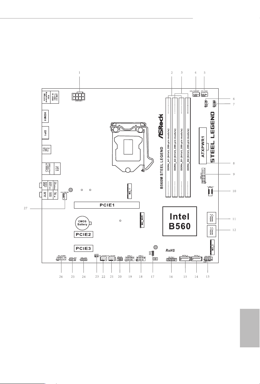
1.3 Motherboard Layout
B560M Steel Legend
English
7

No. Description
1 12V Power Connector (ATX12V1)
2 2 x 288-pin DDR4 DIMM Slots (DDR4_A1, DDR4_B1)
3 2 x 288-pin DDR4 DIMM Slots (DDR4_A2, DDR4_B2)
4 CPU/Water Pump Fan Connector (CPU_FAN2/WP)
5 CPU Fan Connector (CPU_FAN1)
6 Addressable LED Header (ADDR_LED1)
7 RGB LED Header (RGB_LED1)
8 ATX Power Connector (ATXPWR1)
9 USB 3.2 Gen1 Header (USB3_ 5_6)
10 Front Panel Type C USB 3.2 Gen2x2 Header (F_USB3_TC_1)
11 SATA3 Connector (SATA3_2) (Upper), SATA3 Connector (SATA3_3) (Lower)
12 SATA3 Connector (SATA3_4) (Upper), SATA3 Connector (SATA3_5) (Lower)
13 System Panel Header (PANEL1)
14 SATA3 Connector (SATA3_1)
15 SATA3 Connector (SATA3_0)
16 SPI TPM Header (SPI_TPM_J1)
17 POST Status Checker (PSC)
18 USB 2.0 Header (USB5_6)
19 USB 2.0 Header (USB3_4)
20 Chassis Intrusion and Speaker Header (SPK_CI1)
21 Chassis/Water Pump Fan Connector (CHA_FAN2/WP)
22 Chassis/Water Pump Fan Connector (CHA_FAN3/WP)
23 Clear CMOS Jumper (CLRMOS1)
24 RGB LED Header (RGB_LED2)
25 Addressable LED Header (ADDR_LED2)
26 Front Panel Audio Header (HD_AUDIO1)
27 Chassis/Water Pump Fan Connector (CHA_FAN1/WP)
English
8

1.4 I/O Panel
1 2
B560M Steel Legend
5
436
13 911
No. Description No. Description
1 USB 2.0 Ports (USB12) 8 Optica l SPDIF Out Port
2 2.5G LAN RJ-45 Port (Dragon RTL8125BG)* 9 USB 3.2 Gen1 Ports (USB3_3_4)
3 Central / Bass (Orange) 10 USB 3.2 Gen1 Ports (USB3_1_2)
4 Rear Speaker (Black) 11 DisplayPort 1.4
5 Line In (Light Blue) 12 HDMI Port
6 Front Speaker (Lime)** 13 PS/2 Mouse/Keyboard Port
7 Microphone (Pink)
* ere are two LEDs on each LAN port. Please refer to the table below for the LAN port LED indications .
ACT/LINK L ED
SPEED LE D
LAN Por t
Activity / Link LED Speed LED
Status Description Status Description
O No Link O 10Mbps connection
Blinking Data Activity Orange 100Mbps/1Gbps connection
On Link Green 2.5Gbps connection
12
10
78
English
9

** If you use a 2- channel speaker, plea se connect the speake r’s plug into “Front Speaker Jack”. See the table below
for connection d etails in accordance w ith the type of speaker you use.
Audio Output
Channels
2 V — — —
4 V V — —
6 V V V —
8 V V V V
Front Speaker
(No. 6)
Rear Speaker
(No. 4)
Central / Bass
(No. 3)
Line In
(No. 5)
English
10

B560M Steel Legend
Chapter 2 Installation
is is a Micro ATX form factor motherboard. Before you install the motherboard,
study the conguration of your chassis to ensure that the motherboard ts into it.
Pre-installation Precautions
Take note of the following precautions before you install motherboard components
or change any motherboard settings.
Make sure to unplug the power cord before installing or removing the motherboard
•
components. Failure to do so may cause physical injuries and damages to motherboard
components.
In order to avoid damage from static electricity to the motherboard’s components,
•
NEVER place your motherboard directly on a carpet. Also remember to use a grounded
wrist strap or touch a safety grounded object before you handle the components.
Hold components by the edges and do not touch the ICs.
•
Whenever you uninstall any components, place them on a grounded anti-static pad or
•
in the bag that comes with the components.
When placing screws to secure the motherboard to the chassis, please do not over-
•
tighten the screws! Doing so may damage the motherboard.
11
English

2.1 Installing the CPU
1. Before you insert the 120 0-Pin CPU into the socket, please check if the PnP ca p
is on the socket, if the CPU sur face is unclean, or if th ere are any b ent pins in the
socket. Do not force to insert the CPU into the socket if above situ ation is found.
Other wise, the CPU wil l be seriously d amaged.
2. Unplug all power cables be fore installing the CPU.
1
A
B
English
12
2

B560M Steel Legend
3
5
4
13
English

Please save and replace the cover if the processor i s removed. e cover must be
placed if you wish to return the motherboard for aer service.
English
14

2.2 Installing the CPU Fan and Heatsink
1 2
B560M Steel Legend
CPU_FAN
English
15

2.3 Installing Memory Modules (DIMM)
is motherboard provides four 288-pin DDR4 (Double Data Rate 4) DIMM slots,
and supports Dual Channel Memory Technology.
1. For dual channel conguration, you always need to install identica l (the same
brand, speed , size and chip-type) DDR4 DIMM pairs.
2. It is unable to activate Dual Channel Memor y Technology with only one or three
memor y module installed.
3. It is not allowed to install a DDR, DDR2 or DDR3 memory module into a DDR4
slot; otherwise, this motherboard and DIMM may be damaged.
Dual Channel Memory Conguration
Priority DDR4_ A1 DDR4_ A2 DDR4_B1 DDR4_B2
1 Populated Populated
2 Populated Populated Populated Populated
e DIMM only ts in one correct orie ntation. It will cause permanent dam age to
the mothe rboard and the DIMM if you force the DIMM into the slot at incor rect
orientation .
English
16

B560M Steel Legend
1
2
3
English
17

2.4 Expansion Slots (PCI Express Slots)
ere are 3 PCI Express slots on the motherboard.
Before installing an ex pansion card, please make sure that the power supply is
switched o or the power cord is unplugged. Plea se read the documentation of the
expan sion card and mak e necessary hardware settings for the card before you start
the installation.
PCIe slots:
11th Gen Intel® CoreTM Processors:
PCIE1 (PCIe 4.0 x16 slot) is used for PCI Express x16 lane width graphics cards.
PCIE2 (PCIe 3.0 x1 slot) is used for PCI Express x1 lane width cards.
PCIE3 (PCIe 3.0 x1 slot) is used for PCI Express x1 lane width cards.
10th Gen Intel® CoreTM Processors:
PCIE1 (PCIe 3.0 x16 slot) is used for PCI Express x16 lane width graphics cards.
PCIE2 (PCIe 3.0 x1 slot) is used for PCI Express x1 lane width cards.
PCIE3 (PCIe 3.0 x1 slot) is used for PCI Express x1 lane width cards.
For a better ther mal environment, ple ase connect a ch assi s fan to the motherboard’s
chassis fan connector (CHA_ FAN1/WP, CHA_ FAN2/WP or CHA_ FAN3/WP) when
using multiple graphics cards.
English
18

B560M Steel Legend
2.5 Jumpers Setup
e illustration shows how jumpers are setup. When the jumper cap is placed on
the pins, the jumper is “Short”. If no jumper cap is placed on the pins, the jumper is
“Open”.
Clear CMOS Jumper
(CLRMOS1)
(see p.7, No. 23)
CLRMOS1 allows you to clear the data in CMOS. e data in CMOS includes
system setup information such as system password, date, time, and system setup
parameters. To clear and reset the system parameters to default setup, please turn
o the computer and unplug the power cord, then use a jumper cap to short the
pins on CLR MOS1 for 3 seconds. Please remember to remove the jumper cap aer
clearing the CMOS. If you need to clear the CMOS when you just nish updating
the BIOS, you must boot up the system rst, and then shut it down before you do
the clear-CMOS action.
If you clear the CMOS, the case open may be detec ted. Please adjust the BIOS option
“Clear Status” to clear the record of previou s chassis intrusion status.
2-pin Jumper
Short: Clear CMOS
Open: Default
19
English

2.6 Onboard Headers and Connectors
Onboard headers and connectors are NOT jumpers. Do NOT place jumper caps over
these header s and connectors. Placing jumper caps over the headers and connectors
will cause permanent damage to the motherboard.
System Panel Header
(9-pin PANEL1)
(see p.7, No. 13)
PWRBTN (Power Button):
Connec t to the power button on the chassi s front panel. You may congure the way
to turn o your system using the powe r button.
RESET (Reset Button):
Connec t to the reset button on the chassi s front panel. Press the reset button to
restar t the computer if the computer freezes and fails to perform a nor mal restart.
PLED (Syste m Power LED):
Connec t to the power status indicator on the chassis front panel. e LED i s on when
the system is ope rating. e LED keeps blinking when the system i s in S1/S3 sleep
state. e LED is o when the system is in S4 sleep state or powered o (S5).
HDLED (Ha rd Drive Activity LED):
Connec t to the hard drive ac tivity LED on the chassis front panel. e LED is on
when the hard drive i s reading or writing data.
e front panel de sign may dier by chassis. A front pane l module mainly consists
of power button , reset button, power LED, hard dr ive activity LED, speaker and etc.
When connecting your chassis front panel module to this head er, make sure the wire
assig nments and the pin assig nments are matched correctly.
1
PLE D+
PLE D-
HDL ED-
HDL ED+
PWR BTN #
GND
RES ET#
GND
GND
Connect the power
button, reset button and
system status indicator on
the chassis to this header
according to the pin
assignments below. Note
the positive and negative
pins before connecting
the cables.
English
20
Chassis Intrusion and
Speaker Header
(7-pin SPK_CI1)
(see p.7, No. 20)
DUM MY
+5V
1
SIG NAL
DUM MY
GND
DUM MY
Please connect the
chassis intrusion and the
chassis speaker to this
header.

B560M Steel Legend
Serial ATA3 Connectors
Right Angle:
(SATA3_2:
see p.7, No. 11) (Upper)
(SATA3_3:
see p.7, No. 11) (Lower)
(SATA3_4:
see p.7, No. 12) (Upper)
(SATA3_5:
see p.7, No. 12) (Lower)
Vertical:
(SATA3_0:
see p.7, No. 15)
(SATA3_1:
see p.7, No. 14)
USB 2.0 Headers
(9-pin USB3_4)
(see p.7, No. 19)
(9-pin USB5_6)
(see p.7, No. 18)
SATA3_0
USB _PW R
1
USB _PW R
SATA3_2
SATA3_4
SATA3_1
P-
P+
GND
GND
P+
P-
DUM MY
ese six SATA3
connectors support SATA
data cables for internal
SATA3_3
storage devices with up to
6.0 Gb/s data transfer rate.
SATA3_5
* If M2_2 is occupied by
a SATA-type M.2 device,
SATA3_1 will be disabled.
ere are two headers
on this motherboard.
Each USB 2.0 header can
support two ports.
USB 3.2 Gen1 Header
(19-pin USB3_5_6)
(see p.7, No. 9)
Front Panel Type C USB
3.2 Gen2x2 Header
(20-pin F_USB3_TC_1)
(see p.7, No. 10)
Vbus
IntA _PA_S SRX-
IntA _PA_S SRX+
GND
IntA _PA_S STX-
IntA _PA_S STX+
GND
IntA _PA_D —
IntA _PA_D +
USB Type-C Cable
VbusVbus
IntA _PB_ SSRX —
IntA _PB_ SSRX +
GND
IntA _PB_ SSTX —
IntA _PB_ SSTX +
GND
IntA _PB_ D-
IntA _PB_ D+
Dumm y
1
ere is one header on
this motherboard. is
USB 3.2 Gen1 header can
support two ports.
ere is one Front
Panel Type C USB 3.2
Gen2x2 Header on this
motherboard. is header
is used for connecting a
USB 3.2 Gen2x2 module
for additional USB 3.2
Gen2x2 ports.
English
21

Front Panel Audio Header
(9-pin HD_AUDIO1)
(see p.7, No. 26)
1. High Denition Audio supports Jack Sensing, but the panel wire on the chassis
must support HDA to function correctly. Please follow the instructions in our
manual and chassis manual to install your system.
2. If you use an AC’97 audio panel, please install it to the front panel audio heade r by
the steps below:
A. Connect Mic_IN (MIC) to MIC2_ L.
B. Conne ct Audio_R (RIN) to OUT2_R and Audio_ L (LIN) to OUT2_ L.
C. Connect Ground (GND) to Ground (GND).
D. MIC_ RET and OUT_RET are for the HD audio panel only. You don’t need to
connec t them for the AC’97 audio panel.
E. To activate the front mic, go to the “FrontMic” Tab in the Realtek Control panel
and adju st “Recording Volume”.
1
GND
PRE SEN CE#
MIC 2_R
MIC 2_L
MIC _RE T
J_S ENS E
OUT 2_R
OUT _RE T
OUT 2_L
is header is for
connecting audio devices
to the front audio panel.
English
22
Chassis/Water Pump Fan
Connectors
(4-pin CHA_FAN1/WP)
(see p.7, No. 27)
(4-pin CHA_FAN2/WP)
(see p.7, No. 21)
(4-pin CHA_FAN3/WP)
(see p.7, No. 22)
CPU Fan Connector
(4-pin CPU_FAN1)
(see p.7, No. 5)
GND
1
FAN_VOLTAGE
2
CHA _FA N_S PEE D
3
FAN _SP EED _CO NTR OL
4
FAN _VO LT AGE
CHA _FA N_S PE ED
FAN _SP EED _C ONT ROL
1 2 3 4
FAN_ SP EED _CO NT ROL
CPU _FA N_S PEE D
+12 V
GND
4 3 2 1
is motherboard provides three
4-Pin water cooling
chassis
fan
connectors. If you plan to con-
nect a 3-Pin
chassis
water cooler
fan, please connect it to Pin 1-3.
is motherboard
provides a 4-Pin CPU fan
(Quiet Fan) connector.
If you plan to connect a
3-Pin CPU fan, please
connect it to Pin 1-3.

B560M Steel Legend
CPU/Water Pump Fan
Connector
(4-pin CPU_FAN2/WP)
(see p.7, No. 4)
ATX Power Connector
(24-pin ATXPWR1)
(see p.7, No. 
ATX 12V Power
Connector
(8-pin ATX12V1)
(see p.7, No. 1)
CPU_ FAN_SP EED
FAN_ VOLTA GE
GND
1 2 3 4
12
24
1
13
4
is motherboard
provides a 4-Pin water
cooling CPU fan
connector. If you plan
to connect a 3-Pin CPU
water cooler fan, please
connect it to Pin 1-3.
is motherboard pro-
vides a 24-pin ATX power
connector. To use a 20-pin
ATX power supply, please
plug it along Pin 1 and Pin
13.
is motherboard
provides a 8-pin ATX 12V
1
power connector. To use a
4-pin ATX power supply,
please plug it along Pin 1
and Pin 5.
*Warning: Please make
sure that the power cable
connected is for the CPU
and not the graphics
card. Do not plug the
PCIe power cable to this
connector.
SPI TPM Header
(13-pin SPI_TPM_J1)
(see p.7, No. 16)
SPI _ DQ3
1
SPI _ DQ2
+3. 3 V
Dum m y
SPI _ MIS O
SPI _ CS0
CLK
SPI _ MOS I
GND
RSM R ST#
RST #
TPM _ PIR Q
SPI _ TPM _CS #
is connector supports SPI
Trusted Platform Module (TPM)
system, which can securely store
keys, digital certicates, pass-
words, and data. A TPM system
also helps enhance network
security, protects digital
identities, and ensures platform
integrity.
English
23
Loading…
Manuals.eu
- Manuals.eu
- ASRock
- Computers & Peripherals
- Mainboards
- B560M Steel Legend
- User Manual
×
1
2
3
4
5
6
7
8
9
10
11
12
13
14
15
16
17
18
19
20
21
22
23
24
25
26
27
28
29
30
31
32
33
34
35
36
37
38
39
40
41
42
43
44
45
46
47
48
49
50
51
52
53
54
55
56
57
58
59
60
61
62
63
64
65
66
67
68
69
70
71
72
73
74
75
76
77
78
79
80
81
82
83
84
85
86
87
88
89
90
91
92
93
94
95
96
97
⟨
⟩
Copyright © Manuals.eu
Agreement
Privacy Policy
Contact us
Обзор | ASRock B560M Steel Legend Micro-ATX
ASRock отправила нам B560M Steel Legend для обзора. Это материнская плата Micro-ATX с набором микросхем Intel B560, который является более доступным входом в платформу Intel с поддержкой PCIe 4.0.
ASRock продает материнские платы Steel Legend как прочные модели с неотразимой эстетикой. Первое можно проверить, но второе — спорно. В любом случае, этот поставляется с четырьмя слотами DIMM, одним слотом PCIe 4.0 x16 и одним слотом PCIe 4.0 x4 M.2. Плата также поддерживает Wi-Fi через свой третий слот M.2, зарезервированный для этой цели.
Раскрытие информации: ASRock отправила эту материнскую плату B560 в качестве образца носителя для целей этого обзора. Компания не заплатила мне за то, чтобы я сказал что-то конкретное. Тем не менее, все мысли и мнения принадлежат мне.
- Ссылка продукта: ASRock> B560M Steel Legend
- Доступность: выпущена, возможно, не во всем мире
- Цена: 8240 PHP, Розничная торговля
Технические спецификации
| процессор | |
| Поддержка процессора | Intel 11-го / 10-го поколения Core, Pentium Gold, процессоры Celeron |
| Набор микросхем | Intel B560 |
| Розетка | Разъем Intel LGA1200 |
| Память | |
| SDRAM | DDR4 без ECC, ECC в режиме без ECC |
| слот | 2x DIMM |
| Канал | Двойной канал |
| частота | 4800 МГц (макс.) |
| Пропускная способность | 128 ГБ (макс.) |
| Графика | |
| Выходной сигнал дисплея | 1x DisplayPort 1.4, 1x HDMI 2.0 |
| Multi-GPU | — |
| расширение | |
| PCI Express | 1x PCIe 4.0 x16, 2x PCIe 3.0 x1 |
| разветвление | — |
| СХД | |
| SATA | 4 порта SATA |
| M.2 | 3 порта M.2 (PCIe 4.0 x4, PCIe 3.0 x4, 2230) |
| RAID | — |
| Cеть | |
| Проводная | 1x Дракон RTL8125BG |
| Беспроводной сети | — |
| Аудио | |
| DAC | Realtek ALC897 |
| Усилитель | Встроенный |
| Порты | 5x 3.5 мм (задний, центральный, линейный, динамик, микрофон), 1x SPDIF |
| USB | |
| USB 2.0 | 2x сзади, 2x заголовок |
| USB 3.2 Gen 1 | 4x Type-A сзади, 1x заголовок |
| USB 3.2 Gen 2 | 1x заголовок |
| USB 3.2 Gen 2 × 2 | 1x заголовок |
| Thunderbolt 4 | — |
| Заголовки | |
| Вентилятор | 5x ШИМ (процессор, помпа, дополнительный) |
| LED | 4x светодиода (RGB, адресный) |
| Размеры | |
| Длина | 240мм |
| Ширина | 240мм |
| Высота | 45мм |
| Вес | — |
Упаковка и аксессуары
ASRock упаковала легенду B560M Steel в их обычную мягкую упаковку.
Внутри продукта находятся следующие предметы:
- 2x кабеля SATA
- 2 винта M.2 SSD
- 1x винт с шестигранной головкой M.2
- спинная часть кирасы
- Наклейки ASRock
- Поддержка DVD
- Руководство пользователя
- Инструкция по прошивке
- 2 ремня на липучке
Здесь у нас есть самое необходимое, а также некоторые дополнения.
Дизайн, сборка и возможности подключения
ASRock выбрала белый и серебристый цвета для цветовой гаммы B560M Steel Legend. Это приятный контраст с остальными компонентами платы. Теперь, помимо темы, все решения для пассивного охлаждения платы сделаны из алюминия — от VRM, слота M.2 и до PCH. Жаль, что у нас его нет для второго слота M.2.
На задней панели показано, как паять плату. Здесь нет никаких красных флажков, но вы должны убедиться, что ничего не касается танталового конденсатора рядом с PCH.
ЦП питается от 10-фазной схемы питания с дросселями на 60 А и полевыми МОП-транзисторами, расположенными под алюминиевыми радиаторами. У нас также есть два из пяти разъемов для вентиляторов и два 4-контактных разъема для светодиодов.
Что касается заголовков хранилища, у нас здесь обычные подозреваемые. Обычно, хотя вы получаете USB 3.2 Gen 2 × 2 на задней панели ввода-вывода, ASRock решила разместить для него разъем Type-C. Если вам нужен сверхбыстрый интерфейс, вам действительно нужен чехол, с которым можно было бы договориться.
Нижний ряд как обычно занят. Здесь у нас есть второй слот M.2 вместе с третьим, зарезервированным для модулей Wi-Fi в форм-факторе 3 (Key E). Здесь же расположены дополнительный вентилятор и разъемы для светодиодов.
Порты ввода / вывода на задней панели неплохие. Последние протестированные мной платы не имеют SPDIF, поэтому я высоко оценил усилия ASRock по включению его здесь вместе с устаревшим портом PS / 2.
Доска выглядит прочной и хорошо продуманной из коробки. ASRock даже пошла с открытыми слотами PCI 3.0 x1, чтобы убедиться, что он может поддерживать физически более длинные интерфейсы с поддержкой x1.
Интерфейс прошивки
ASRock пошла на простой с UEFI B560M Steel Legend. Простой режим — это то, чем он является, с ярлыками для его функций и статистикой самых важных датчиков.
Здесь есть 8 основных меню с OC Tweaker, которые вы можете перейти в меню для настройки CPU, DRAM и напряжения. Обратите внимание, что разгон разрешен только для памяти. Для разгона процессора вам действительно нужна материнская плата на чипсете Z590.
Расширенный, конечно, там, где можно найти параметры PCH. Параметры, связанные с состоянием питания ЦП, также находятся в этом меню.
Инструмент — это то место, где расположены определяющие особенности материнской платы. Здесь можно отключить RGB-подсветку полупрозрачного логотипа Steel Legend вместе с сетевой поддержкой клиентов. Вы даже можете безопасно стереть свой SSD здесь перед установкой Windows или желаемая вами ОС.
Монитор H / W не требует пояснений. Здесь тонны датчиков с приличной частотой обновления.
FAN-Tastic Tuning — это довольно простой профилировщик скорости вращения вентилятора. Здесь нет специального коллектора насоса, поэтому убедитесь, что насос постоянно работает на 100% для более стабильной работы.
Прошивка хорошая. ASRock даже добавила для него мини-руководство. Однако поддержки RAID нет.
Настройка теста и методология
Производительность системы оценивается с помощью стандартных отраслевых инструментов тестирования и реальных приложений, если это необходимо. Система протестирована со следующими конфигурациями программного обеспечения:
- Конфигурация UEFI: по умолчанию
- Windows План питания: сбалансированный
- Windows Игровой режим: отключен
- Windows Игровая панель: отключена
- Windows Безопасность: отключено
Ниже приведены спецификации тестовой системы, а также программное обеспечение и / или приложения, использованные для обзора:
| Характеристики тестовой системы | |
| ЦП | Intel Core i9-11900 |
| Материнская плата | ASRock B560M Стальная легенда |
| охладитель | Noctua NH-U12S Редукс |
| Память | ADATA Premier 2666 МГц, 16 ГБ |
| GPU / ГРАФИЧЕСКИЙ ПРОЦЕССОР | ASUS Phoenix GTX 1660 SUPER 6 ГБ |
| СХД | Plextor M9Pe PCIe 3.0 NVMe 512 ГБ |
| Коробка | Механическая библиотека JXK-K3 |
| БЛОКИ ПИТАНИЯ | Thermaltake Toughpower GF1 650 Вт |
| Монитор | LG UF680T |
| OS | Microsoft Windows 10 Pro 64-бит |
Температура, мощность и шум:
- AIDA64 Extreme Edition — Тест стабильности системы
ЦП, память и графический процессор:
- AIDA64 Extreme Edition — быстрый отчет, кэш и память, тест GPGPU
Хранение:
- CrystalDiskMark — последовательный тест
аудио:
- RightMark Audio Analyzer — Отчет о тестировании
Сети:
- NetIO-GUI — скорость передачи данных по сети
Мы использовали тест стабильности системы AIDA64, чтобы проверить, как система справляется с тепловыми потоками. Для этого измерения мы загрузили стресс-тест с ЦП в качестве единственной включенной опции. Показания температуры снимаются с HWiNFO при температуре окружающей среды 27 ° C. Кулером процессора, использованным в этом тесте, является Noctua NH-U12S Redux.
| Модель | VRM, ° C | Чипсет, ° C | M.2, ° С | |||||||||||||||||||||||||||||||||||||||||||||||||||||||||||||||||||||||||||||||||||||||||||||
| ASRock B560M Стальная легенда | 36
60 |
|||||||||||||||||||||||||||||||||||||||||||||||||||||||||||||||||||||||||||||||||||||||||||||||
| ASUS Z590-I Игры | 40
62 |
|||||||||||||||||||||||||||||||||||||||||||||||||||||||||||||||||||||||||||||||||||||||||||||||
| GIGABYTE Z590I Vision D | 39
64 |
|||||||||||||||||||||||||||||||||||||||||||||||||||||||||||||||||||||||||||||||||||||||||||||||
| ASUS B550-I Игры | 34
Первым делом в обзоре стоит температура процессора, на которую влияют как мощность, так и профиль вентилятора. Здесь мы могли видеть, что Core i9-11900K достигает 70 ° C, что все еще хорошо, учитывая пиковое значение vCore — подробнее об этом позже. VRM, набор микросхем и основной твердотельный накопитель M.2 сохранили отличную тепловую мощность, хотя и под нагрузкой. Также проверяется общая мощность системы. Затем показания мощности записываются с помощью ваттметра, а показания напряжения для Vcore и наиболее распространенных шин снимаются с помощью HWiNFO.
|