

Регистрация устройства поможет вам управлять его гарантией, получать техническую поддержку и отслеживать статус ремонта.
Апгрейд гарантии: здесь.
* Обращаем ваше внимание, что доступность устройств с гарантией Premium Care зависит от региона.
Регистрация продукта

- Продукты, сертифицированные Федеральной комиссией по связи и Министерством промышленности Канады, будут распространяться в США и Канаде. Информацию о них можно получить на соответствующих региональных сайтах ASUS.
- Технические характеристики могут быть изменены без предварительного уведомления. Точную информацию о них вы можете получить у продавца. Доступность продуктов зависит от региона.
- Технические характеристики зависят от конкретной модели продукта – см. страницу спецификаций. Все изображения служат лишь для целей иллюстрации.
- Цвет печатной платы и версии приложенных программ могут быть изменены без предварительного уведомления.
- Упомянутые выше названия продуктов являются торговыми марками соответствующих компаний.
- Термины HDMI и HDMI High-Definition Multimedia Interface, оформление HDMI-изделий и логотипы HDMI – торговые марки или зарегистрированные торговые марки компании HDMI Licensing Administrator, Inc.
-
- Технические характеристики зависят от конкретной модели продукта – точную информацию ищите на странице спецификаций. Все изображения служат лишь для целей иллюстрации.
- Данный продукт (электрическое или электронное оборудование, содержащие ртуть батарейки) не следует выбрасывать с остальными городскими отходами. Ознакомьтесь с местными правилами утилизации электронных продуктов.
- Использование на сайте символа торговой марки (™ или ®) означает, что соответствующий текст, логотип или слоган используется как торговая марка на основе общего права и/или зарегистрирован как торговая марка в США и/или других странах/регионах.
Displayed below is the user manual for PRIME Z270-P by ASUS which is a product in the Motherboards category.
This manual has pages.

Motherboard Pin
Denition
1
E11133
Revised Edition v2
December 2015

1-2 Motherboard Pin Denition
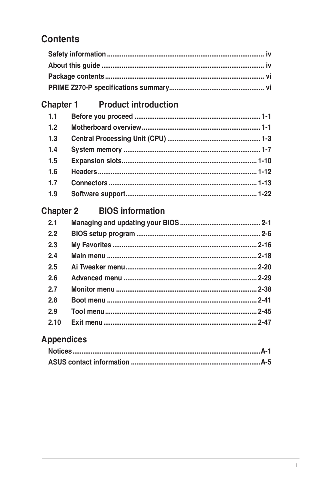
Contents
Motherboard Pin Definition 1-1
1 Headers …………………………………………………………………………………………. 1-3
2 Jumpers …………………………………………………………………………………………1-4
3 Internal Connectors ………………………………………………………………………..1-6
4 Onboard LEDs ……………………………………………………………………………… 1-16
5 Onboard buttons and switches ……………………………………………………..1-17
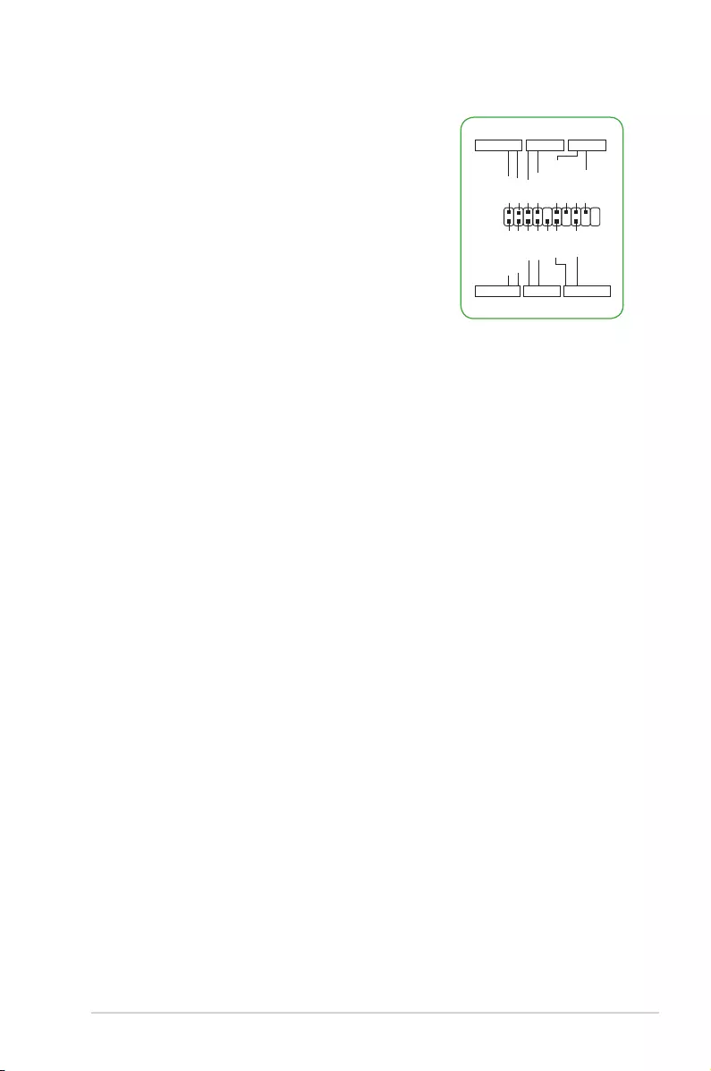
Motherboard Pin Denition 1-3
1 Headers
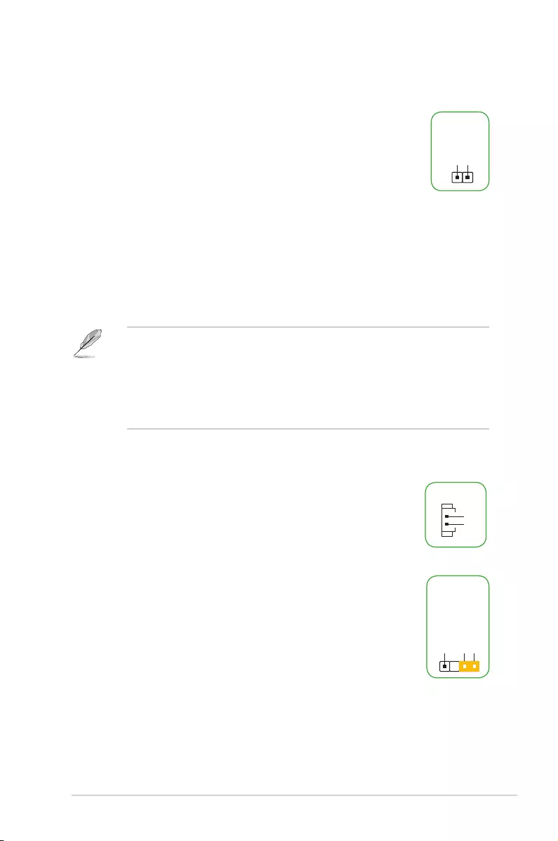
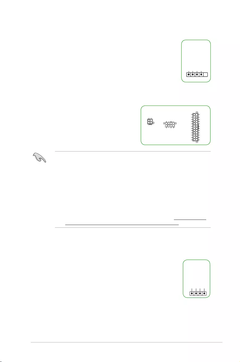
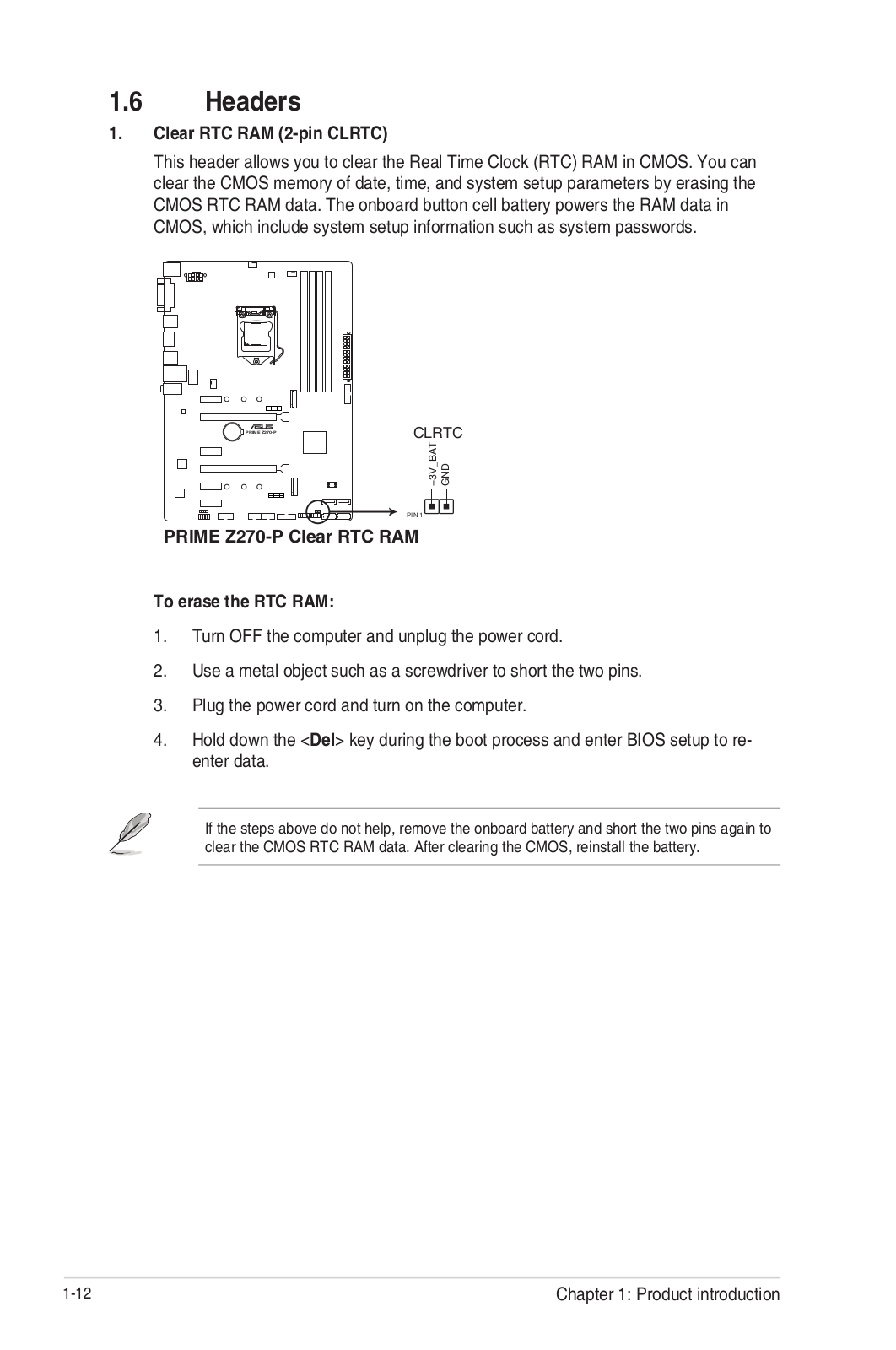
1. Clear RTC RAM (2-pin CLRTC)
This header allows you to clear the Real Time Clock (RTC) RAM in
CMOS. You can clear the CMOS memory of date, time, and system setup
parameters by erasing the CMOS RTC RAM data. The onboard button
cell battery powers the RAM data in CMOS, which include system setup
information such as system passwords.
To erase the RTC RAM:
1. Turn OFF the computer and unplug the power cord.
2. Use a metal object such as a screwdriver to short the two pins.
3. Plug the power cord and turn ON the computer.
4. Hold down the <Del> key during the boot process and enter BIOS setup to re-
enter data.
• Ifthestepsabovedonothelp,removetheonboardbatteryandshortthetwopins
again to clear the CMOS RTC RAM data. After clearing the CMOS, reinstall the
battery.
• YoudonotneedtocleartheRTCwhenthesystemhangsduetooverclocking.For
system failure due to overclocking, use the CPU Parameter Recall (C.P.R.) feature.
Shut down and reboot the system, then the BIOS automatically resets parameter
settings to default values.
2. RTC Battery header (2-pin BATT_CON)
This connector is for the lithium CMOS battery.
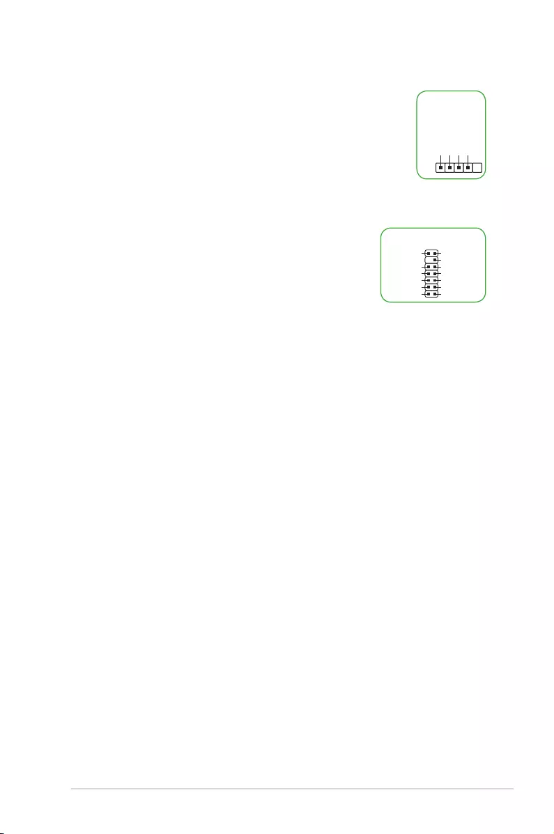
3. Chassis intrusion header (4-1 pin CHASSIS)
This header is for a chassis-mounted intrusion detection sensor or
switch. Connect one end of the chassis intrusion sensor or switch cable
to this connector. The chassis intrusion sensor or switch sends a high-
level signal to this connector when a chassis component is removed or
replaced. The signal is then generated as a chassis intrusion event.
By default, the pin labeled “Chassis Signal” and “Ground” are shorted
with a jumper cap. Remove the jumper caps only when you intend to use
the chassis intrusion detection feature.
CLRTC
+3V_BAT
GND
PIN 1
+5VSB_MB
Chassis Signal
GND
CHASSIS
1-4 Motherboard Pin Denition
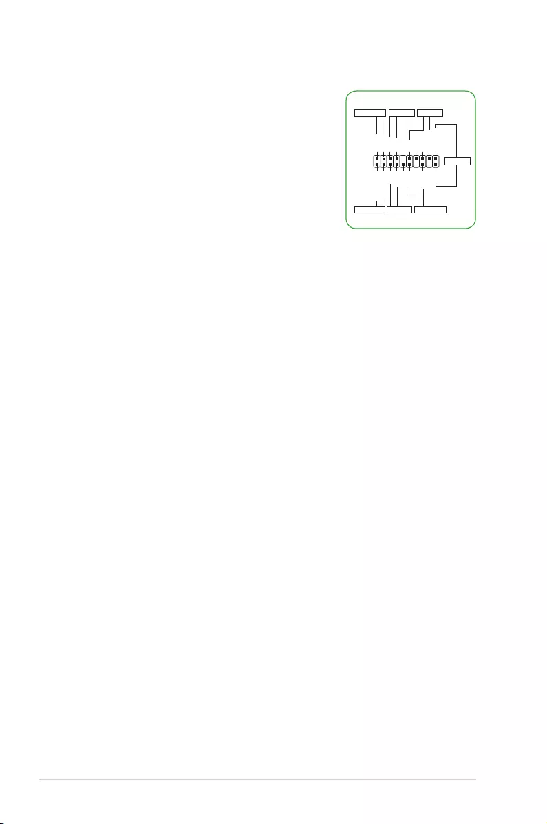
2 Jumpers
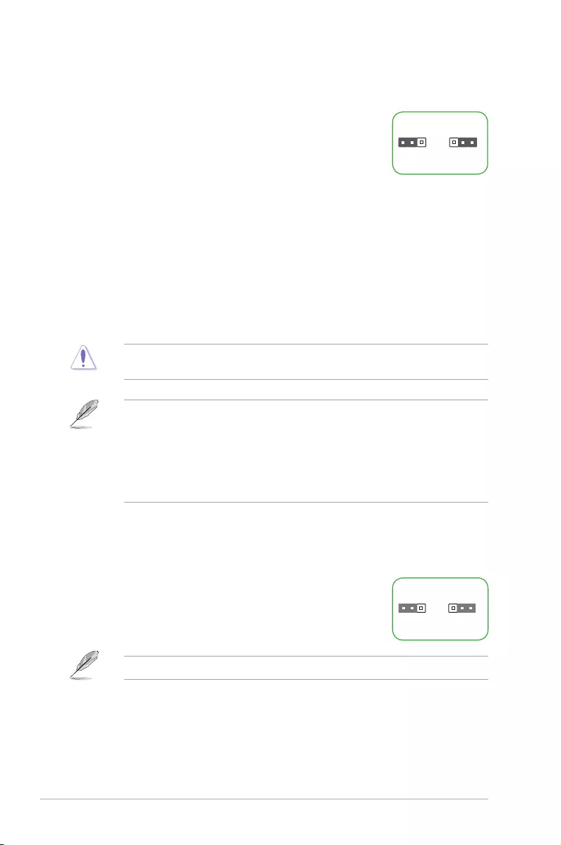
1. Clear RTC RAM (3-pin CLRTC)
This jumper allows you to clear the Real Time Clock (RTC)
RAM in CMOS. You can clear the CMOS memory of date, time,
and system setup parameters by erasing the CMOS RTC RAM
data. The onboard button cell battery powers the RAM data in
CMOS, which include system setup information such as system
passwords.
To erase the RTC RAM:
1. Turn OFF the computer and unplug the power cord.
2. Move the jumper cap from pins 1-2 (default) to pins 2-3. Keep the cap on pins 2-3
for about 5~10 seconds, then move the cap back to pins 1-2.
3. Plug the power cord and turn ON the computer.
4. Hold down the <Del> key during the boot process and enter BIOS setup to
reenter data.
Except when clearing the RTC RAM, never remove the cap on CLRTC jumper default
position. Removing the cap will cause system boot failure!
• Ifthestepsabovedonothelp,removetheonboardbatteryandmovethejumper
again to clear the CMOS RTC RAM data. After clearing the CMOS, reinstall the
battery.
• YoudonotneedtocleartheRTCwhenthesystemhangsduetooverclocking.For
system failure due to overclocking, use the CPU Parameter Recall (C.P.R) feature.
Shut down and reboot the system so the BIOS can automatically reset parameter
settings to default values.
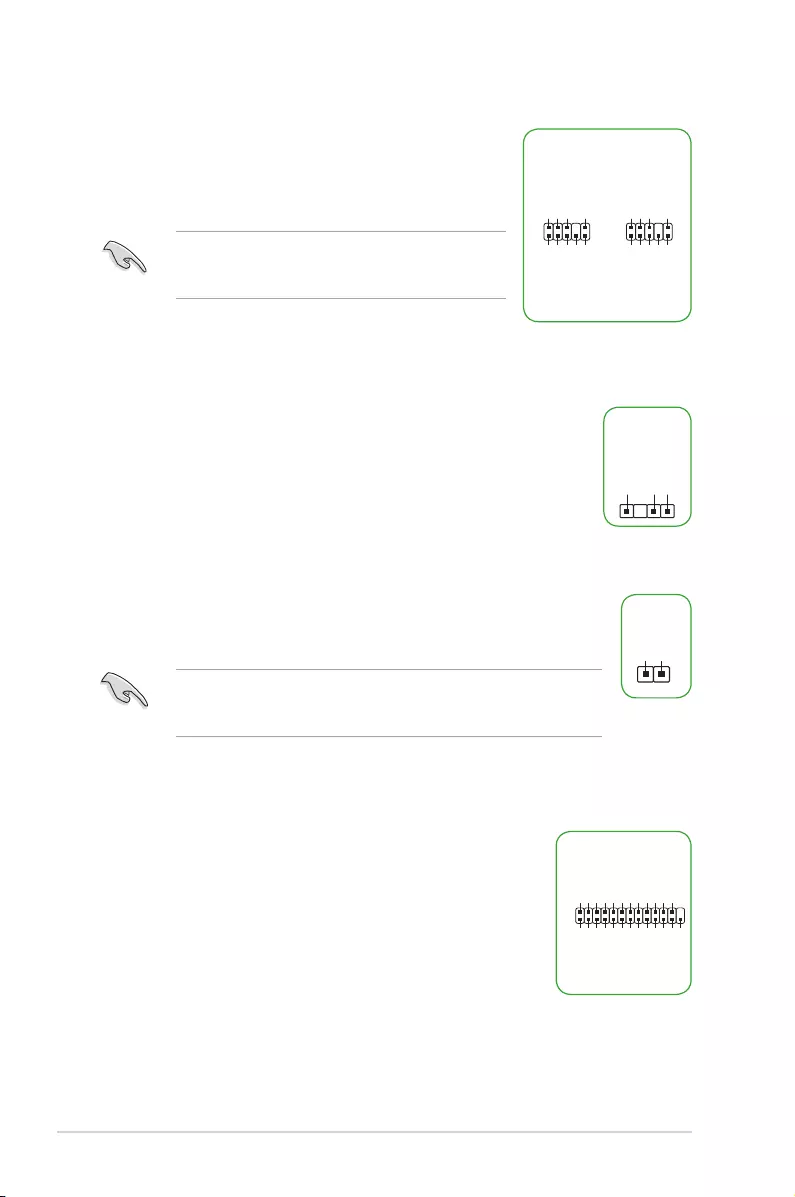
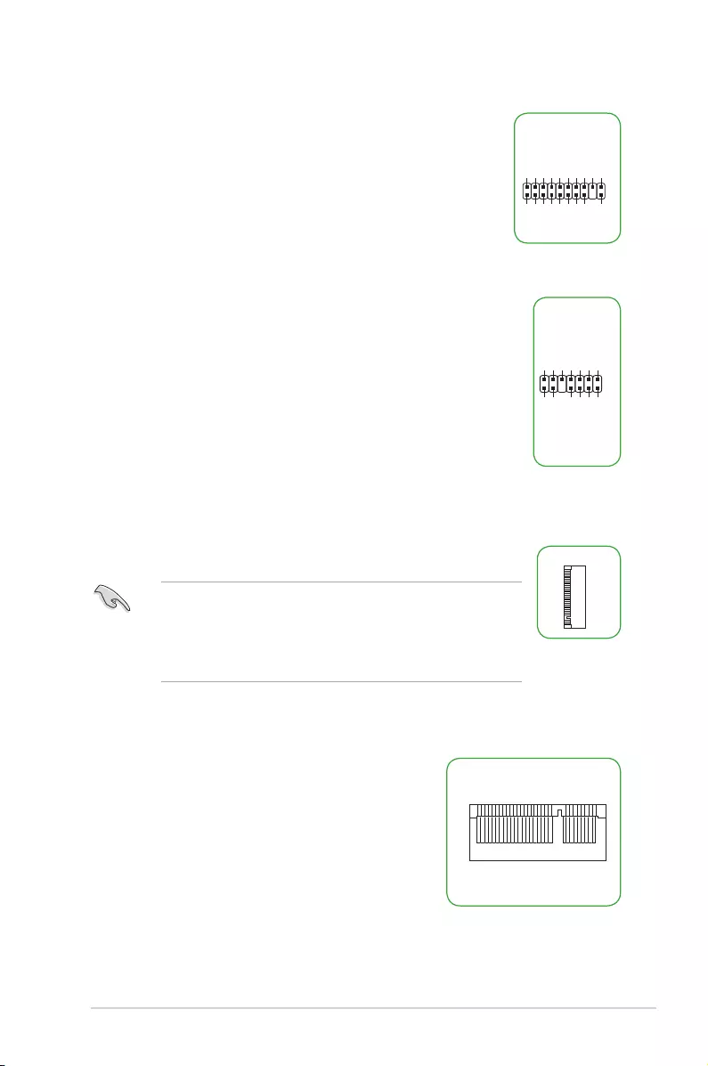
2. Intel® ME jumper (3-pin DIS_ME)
This jumper allows you to enable or disable the Intel® ME
function. Set this jumper to pins 1-2 to enable (default) the Intel®
ME function and to pins 2-3 to disable it.
122 3
Normal
(Default)
Clear RTC
CLRTC
2 2 3
Normal
(Default)
Disable ME
DIS_ME
1
Disable the Intel® ME function before updating it.
Motherboard Pin Denition 1-5
3. USB device wake-up (3-pin USBPWF)
Set these jumpers to +5V to wake up the computer from S1 sleep
mode (CPU stopped, DRAM refreshed, system running in low power
mode) using the connected USB devices. Set to +5VSB to wake
up from S3 and S4 sleep modes (no power to CPU, DRAM in slow
refresh, power supply in reduced power mode).
• TheUSBdevicewake-upfeaturerequiresapowersupplythatcanprovide500mAon
the +5VSB lead for each USB port; otherwise, the system would not power up.
• ThetotalcurrentconsumedmustNOTexceedthepowersupplycapability(+5VSB)
whether under normal condition or in sleep mode.
21 2 3
+5V
(Default)
+5VSB
USBPWF
4. Keyboard and USB device wake up (3-pin KB_USBPWB)
This jumper allows you to enable or disable the keyboard and
USB device wake-up feature. When you set this jumper to pins
2-3 (+5VSB), you can wake up the computer by pressing a key on
thekeyboard.ThisfeaturerequiresanATXpowersupplythatcan
supply at least 1A on the +5VSB lead, and a corresponding setting
in the BIOS.
+5V +5VSB
(Default)
KB_USBPWB
1 2
2 3
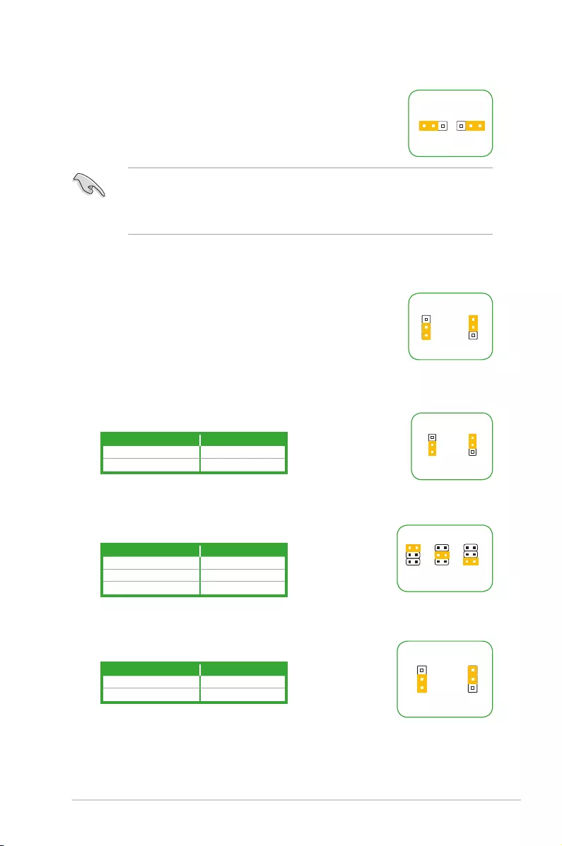
5. Display panel backlight power selector (3-pin BLKT_PWR_SEL)
1 2
2 3
12V
(Default)
19V
BLKT_PWR_SEL
6. Display panel VCC power selector (VCC_PWR_SEL)
1
3V
(Default)
2
5V
3
12V
VCC_PWR_SEL
Pins Setting
1-2 (Default) 12V
2-3 19V
Pins Setting
1 (Default) 3V
2 5V
3 12V
7. LVDS panel/eDP selector (3-pin FPD_SEL)
1 2
2 3
for LVDS
(Default)
for eDP
FPD_SEL
Pins Setting
1-2 (Default) LVDS
2-3 eDP
1-6 Motherboard Pin Denition
3 Internal Connectors
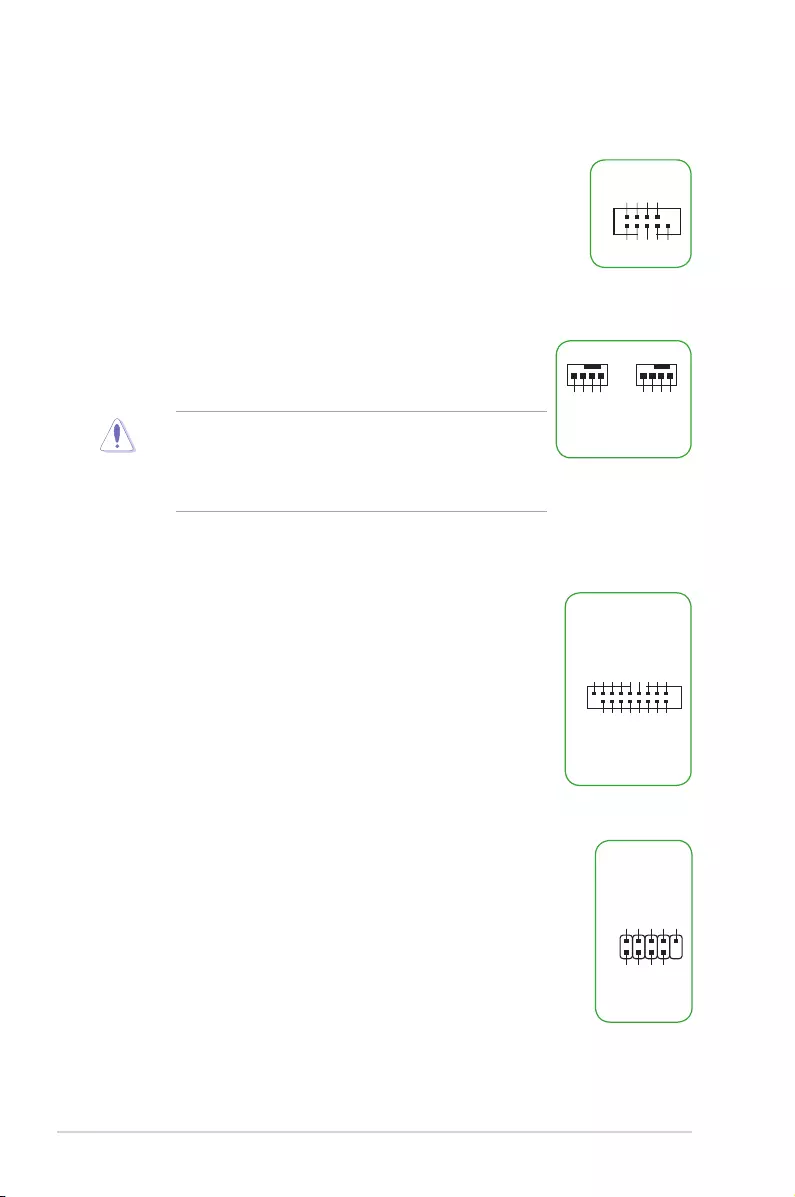
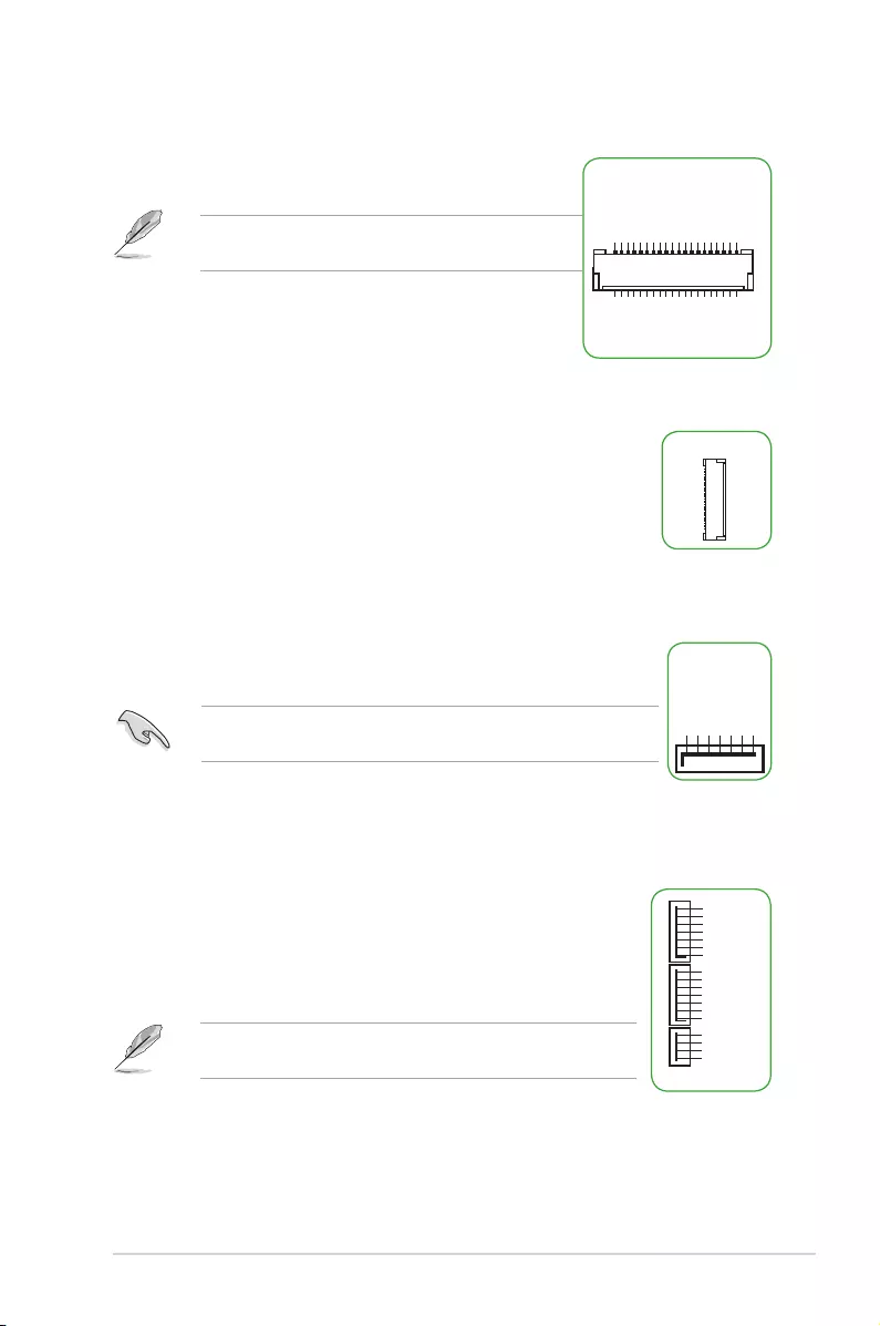
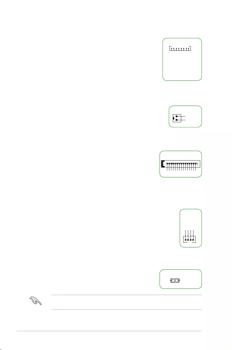
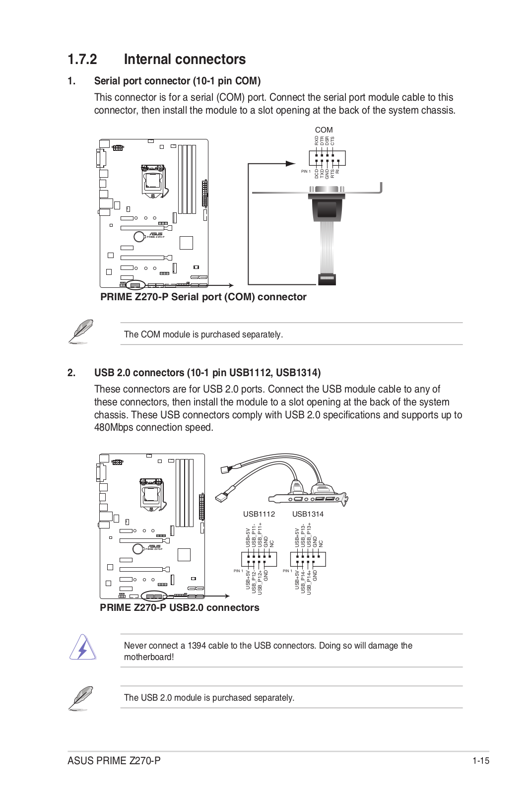
1. Serial port connector (10-1 pin COM)
This connector is for a serial (COM) port. Connect the serial port
module cable to this connector, then install the module to a slot
opening at the back of the system chassis.
2. CPU and chassis fan connectors (4-pin CPU_FAN, 4-pin CHA_FAN)
Connect the fan cable to the fan connector on the motherboard,
ensuring that the black wire of the cable matches the ground pin
of the connector
Do not forget to connect the fan cables to the fan connectors.
Insufcientairowinsidethesystemmaydamagethe
motherboard components. These are not jumpers! Do not place
jumper caps on the fan connectors! The CPU_FAN connector
supports a CPU fan of maximum 1A (12 W) fan power.
PIN 1
COM
DCD
TXD
GND
RTS
RI
RXD
DTR
DSR
CTS
CPU_FAN
CPU FAN PWM
CPU FAN IN
CPU FAN PWR
GND
+5V
CHA FAN IN
CHA FAN PWR
GND
CHA_FAN
C
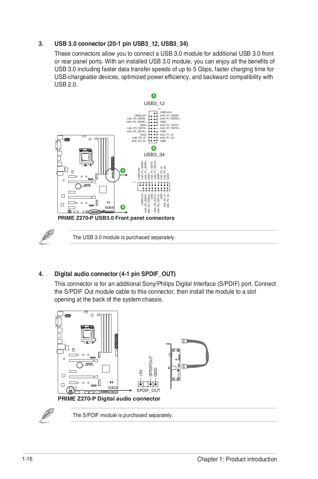
3. USB 3.0 connector (20-1 pin)
This connector allows you to connect a USB 3.0 module for
additional USB 3.0 front or rear panel ports. With an installed USB
3.0module,youcanenjoyallthebenetsofUSB3.0including
faster data transfer speeds of up to 5 Gbps, faster charging time
forUSB-chargeabledevices,optimizedpowerefciency,and
backward compatibility with USB 2.0.
4. USB 2.0 connector (10-1 pin)
This connector is for USB 2.0 ports. Connect the USB module cable
to this connector, then install the module to a slot opening at the back
of the system chassis. This USB connector complies with USB 2.0
specicationsandsupportsupto480Mbpsconnectionspeed.
USB3
PIN 1
USB3+5V
IntA_P1_SSRX-
IntA_P1_SSRX+
GND
IntA_P1_SSTX-
IntA_P1_SSTX+
GND
IntA_P1_D-
IntA_P1_D+
GND
USB3+5V
IntA_P2_SSRX-
IntA_P2_SSRX+
GND
IntA_P2_SSTX-
IntA_P2_SSTX+
GND
IntA_P2_D-
IntA_P2_D+
USB
PIN 1
USB+5V
USB_P11-
USB_P11+
GND
NC
USB+5V
USB_P12-
USB_P12+
GND
Motherboard Pin Denition 1-7
5. Single USB 2.0 connector (5-1 pin)
This connector is for a USB 2.0 port. Connect the USB module cable
to this connector, then install the module to a slot opening at the back
of the system chassis. This USB connector complies with USB 2.0
specicationsandsupportsupto480Mbpsconnectionspeed.
PIN 1
USBE5
+5V DC
Data(negative)
Data(positive)
Groud
•
Forafullyconguredsystem,werecommendthatyouuseapowersupplyunit
(PSU)thatcomplieswithATX12VSpecication2.0(orlaterversion)andprovidesa
minimum power of 350 W.
•
DONOTforgettoconnectthe4-pin/8-pinATX+12Vpowerplug.Otherwise,the
system will not boot up.
• WerecommendthatyouuseaPSUwithhigherpoweroutputwhenconguringa
system with more power-consuming devices or when you intend to install additional
devices. The system may become unstable or may not boot up if the power is
inadequate.
•
Ifyouareuncertainabouttheminimumpowersupplyrequirementforyoursystem,
refer to the Recommended Power Supply Wattage Calculator at http://support.asus.
com/PowerSupplyCalculator/PSCalculator.aspx?SLanguage=en-us for details.
6. ATX power connectors (24-pin EATXPWR, 8-pin EATX12V, 4-pin EATX12V)
TheseconnectorsareforATXpowersupply
plugs.Thepowersupplyplugsaredesignedtot
these connectors in only one orientation. Find the
properorientationandpushdownrmlyuntilthe
connectorscompletelyt.
EATX12V
+12V DC
+12V DC
+12V DC
+12V DC
GND
GND
GND
GND
EATXPWR
PIN 1
PIN 1
GND
+5 Volts
+5 Volts
+5 Volts
-5 Volts
GND
GND
GND
PSON#
GND
-12 Volts
+3 Volts
+3 Volts
+12 Volts
+12 Volts
+5V Standby
Power OK
GND
+5 Volts
GND
+5 Volts
GND
+3 Volts
+3 Volts
ATX12V
PIN 1
+12V DC
+12V DC
GND
GND
7. Speaker connector (4-pin SPEAKER)
The 4-pin connector is for the chassis-mounted system warning speaker.
The speaker allows you hear system beeps and warnings.
+5V
GND
GND
Speaker Out
SPEAKER
PIN 1
1-8 Motherboard Pin Denition
8. Front panel audio connector (10-1 pin AAFP)
This connector is for a chassis-mounted front panel audio
I/O module that supports either HD Audio or legacy AC`97
audio standard. Connect one end of the front panel audio
I/O module cable to this connector.
AAFP
PIN 1
AGND
NC
SENSE1_RETUR
SENSE2_RETUR
PORT1 L
PORT1 R
PORT2 R
SENSE_SEND
PORT2 L
HD-audio-compliant
pin definition
PIN 1
AGND
NC
NC
NC
MIC2
MICPWR
Line out_R
NC
Line out_L
Legacy AC’97
compliant definition
Werecommendthatyouconnectahigh-denitionfront
panel audio module to this connector to avail of the
motherboard’shigh-denitionaudiocapability.
9. Digital audio connector (4-1 pin SPDIF_OUT)
This connector is for an additional Sony/Philips Digital Interface (S/PDIF)
port. Connect the S/PDIF Out module cable to this connector, then install
the module to a slot opening at the back of the system chassis.
10. Direct connector (2-pin DRCT)
This connector is for the chassis-mounted button that supports the
DirectKey function. Connect the button cable that supports DirectKey,
from the chassis to this connector on the motherboard.
Ensure that your chassis comes with the button cable that supports the
DirectKey feature. Refer to the technical documentation that came with the
chassis for details.
11. LPT connector (26-1 pin LPT)
The LPT (Line Printing Terminal) connector supports devices
suchasaprinter.LPTstandardizesasIEEE1284,whichisthe
parallel port interface on IBM PC-compatible computers.
PIN 1
O_LPT_XSTB#_R
O_LPT_XPD0_R
O_LPT_XPD1_R
O_LPT_XPD2_R
O_LPT_XPD3_R
O_LPT_XPD4_R
O_LPT_XPD5_R
O_LPT_XPD6_R
O_LPT_XPD7_R
O_LPT_ACK#_R
O_LPT_BUSY_R
O_LPT_PE_R
O_LPT_SLCT_R
O_LPT_XAFD#_R
O_LPT_ERROR#_R
O_LPT_XINIT#_R
O_LPT_XSLIN#_R
GND
GND
GND
GND
GND
GND
GND
GND
Motherboard Pin Denition 1-9
12. LVDS connector (40-pin LVDS)
This connector is for an LCD monitor that supports Low-
voltage Differential Signaling (LVDS) interface.
Enable LVDS in the BIOS setup if the LVDS output is
disabled by default.
LVDS
PIN 1 PIN 20
PIN 40
PIN 21
ODD_Lane3_P
ODD_Lane3_N
ODD_Lane2_P
ODD_Lane2_N
ODD_Lane1_P
ODD_Lane1_N
ODD_Lane0_P
ODD_Lane0_N
EVEN_Lane3_P
EVEN_Lane3_N
EVEN_Lane2_P
EVEN_Lane2_N
EVEN_Lane1_P
EVEN_Lane1_N
EVEN_Lane0_P
EVEN_Lane0_N
EDID_GND
LCD_VCC
LCD_VCC
LCD_VCC
N/C
EDID_3.3V
LCD_GND
LCD_GND
LCD_GND
ODD_CLK_P
ODD_CLK_N
BKLT_GND
BLKT_GND
BKLT_GND
EDID_CLK
BKLT_ENABLE
BKLT_PWM_DIM
EVEN_CLK_P
EVEN_CLK_N
BKLT_PWR
BKLT_PWR
BKLT_PWR
N/C
EDID_DATA
13. Embedded DisplayPort (40- pin eDP)
This connector is for an internal embedded DisplayPort connection.
14. SATA 6.0Gb/s connectors (7-pin SATA6G)
These connectors connect to SATA 6.0 Gb/s hard disk drives via SATA
6.0 Gb/s signal cables.
SATA6G
GND
RSATA_RXP4
RSATA_RXN4
GND
RSATA_TXN4
RSATA_TXP4
GND
You must install Windows®XPServicePack3orlaterversionbefore
using Serial ATA hard disk drives.
15. SATA EXPRESS connector (7-pin SATA6G, SATAEXPRESS)
This connector connects to SATA 6.0 Gb/s hard disk drives via SATA
6.0 Gb/s signal cables.
If you installed SATA hard disk drives, you can create a RAID 0, 1,
5,and10congurationwiththeIntel® Rapid Storage Technology
through the onboard Intel® chipset.
TheSATAEXPRESSconnectorcansupportoneSATAExpress
device or two SATA devices.
SATAEXPRESS
GND
RSATA_TXP1
RSATA_TXN1
GND
RSATA_RXN1
RSATA_RXP1
GND
GND
RSATA_TXP2
RSATA_TXN2
GND
RSATA_RXN2
RSATA_RXP2
GND
Floating
Device_Reset
GND
Detection
1-10 Motherboard Pin Denition
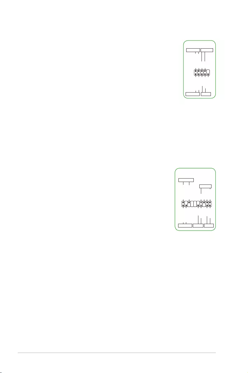
16. System panel connector (10-1 pin F_PANEL)
This connector supports several chassis-mounted functions.
PIN 1
PWR BTN
PWR_LED+
PWR_LED-
PWR
GND
HDD_LED+
HDD_LED-
Ground
HWRST#
(NC)
F_PANEL
+PWR LED
+HDD_LED RESET
• SystempowerLED(2-pinPWR_LED)
This 2-pin connector is for the system power LED. Connect the
chassis power LED cable to this connector. The system power
LED lights up when you turn on the system power, and blinks
when the system is in sleep mode.
• HarddiskdriveactivityLED(2-pinHDD_LED)
This 2-pin connector is for the HDD Activity LED. Connect the
HDD Activity LED cable to this connector. The HDD LED lights
uporasheswhendataisreadfromorwrittentotheHDD.
• ATXpowerbutton/soft-offbutton(2-pinPWR_BTN)
This connector is for the system power button.
• Resetbutton(2-pinRESET)
This 2-pin connector is for the chassis-mounted reset button for system reboot
without turning off the system power.
• SystempowerLED(2-pinPWR_LED)
This 2-pin connector is for the system power LED. Connect
the chassis power LED cable to this connector. The system
power LED lights up when you turn on the system power,
and blinks when the system is in sleep mode.
• HarddiskdriveactivityLED(2-pinHDD_LED)
This 2-pin connector is for the HDD Activity LED. Connect
the HDD Activity LED cable to this connector. The HDD
LEDlightsuporasheswhendataisreadfromorwrittento
the HDD.
• Systemwarningspeaker(4-pinSPEAKER)
This 4-pin connector is for the chassis-mounted system warning speaker. The
speaker allows you to hear system beeps and warnings.
• ATXpowerbutton/soft-offbutton(2-pinPWRSW)
This connector is for the system power button. Pressing the power button turns
the system on or puts the system in sleep or soft-off mode depending on the
BIOS settings. Pressing the power button for more than four seconds while the
system is ON turns the system OFF.
• Resetbutton(2-pinRESET)
This 2-pin connector is for the chassis-mounted reset button for system reboot
without turning off the system power.
System panel connector (20-8 pin PANEL)
This connector supports several chassis-mounted functions.
PIN 1
+PWR_LED-
SPEAKER
PWR_LED+
PWR_LED-
+5V
Ground
Ground
Speaker
HDD_LED+
HDD_LED-
PWR
Ground
Reset
Ground
F_PANEL
+HDD_LED- PWRSW RESET
Motherboard Pin Denition 1-11
• SystempowerLED(4-pin+PWR_LED-)
This 2-pin connector is for the system power LED.
Connect the chassis power LED cable to this
connector. The system power LED lights up when
you turn on the system power, and blinks when the
system is in sleep mode.
• HarddiskdriveactivityLED(2-pin+HDD_LED-)
This 2-pin connector is for the HDD Activity LED.
Connect the HDD Activity LED cable to this
connector.TheHDDLEDlightsuporasheswhen
data is read from or written to the HDD.
• Systemwarningspeaker(4-pinSPEAKER)
This 4-pin connector is for the chassis-mounted system warning speaker. The
speaker allows you to hear system beeps and warnings.
• ATXpowerbutton/soft-offbutton(2-pinPWR_SW)
This connector is for the system power button. Pressing the power button turns
the system on or puts the system in sleep or soft-off mode depending on the
operating system settings. Pressing the power switch for more than four seconds
while the system is ON turns the system OFF.
• Resetbutton(2-pinRESET)
This 2-pin connector is for the chassis-mounted reset button for system reboot
without turning off the system power.
System panel connector (20-5 pin PANEL)
This connector supports several chassis-mounted
functions.
PLED+
PLED-
PWR
Ground
+5V_SPKO
Ground
Ground
Speaker
HDD_LED+
HDD_LED-
Ground
RESET
NC
PLED+
PLED-
PIN 1
+PWR_LED-
+PWR_LED-
SPEAKER
PANEL
+HDD_LED-
PWR_SW
RESET
* Requires an ATX power supply
1-12 Motherboard Pin Denition
• SystempowerLED(4-pin+PWR_LED-)
This 2-pin connector is for the system power LED.
Connect the chassis power LED cable to this
connector. The system power LED lights up when
you turn on the system power, and blinks when the
system is in sleep mode.
• HarddiskdriveactivityLED(2-pin+HDD_LED-)
This 2-pin connector is for the HDD Activity LED.
Connect the HDD Activity LED cable to this connector. The HDD LED lights up
orasheswhendataisreadfromorwrittentotheHDD.
• Systemwarningspeaker(4-pinSPEAKER)
This 4-pin connector is for the chassis-mounted system warning speaker. The
speaker allows you to hear system beeps and warnings.
• ATXpowerbutton/soft-offbutton(2-pinPWR_SW)
This connector is for the system power button. Pressing the power button turns
the system on or puts the system in sleep or soft-off mode depending on the
operating system settings. Pressing the power switch for more than four seconds
while the system is ON turns the system OFF.
• Resetbutton(2-pinRESET)
This 2-pin connector is for the chassis-mounted reset button for system reboot
without turning off the system power.
• Chassisintrusionheader(2-pinCHASSIS)
This connector is for a chassis-mounted intrusion detection sensor or switch.
Connect one end of the chassis intrusion sensor or switch cable to this
connector. The chassis intrusion sensor or switch sends a high-level signal to
this connector when a chassis component is removed or replaced. The signal is
then generated as a chassis intrusion event.
System panel connector (20-3 pin F_PANEL)
This connector supports several chassis-mounted
functions.
PLED+
PLED-
PWR
GND
+5V
GND
GND
Speaker
Intruder#
HDD_LED+
HDD_LED-
GND
Reset
NC
PLED+
PLED-
GND
PIN 1
+PWR_LED-
+PWR_LED-
SPEAKER
PANEL
+HDD_LED-
PWR_SW
RESET
* Requires an ATX power supply
CHASSIS
Motherboard Pin Denition 1-13
17. TPM connector (20-1 pin TPM)
This connector supports a Trusted Platform Module (TPM) system,
whichcansecurelystorekeys,digitalcerticates,passwords,and
data. A TPM system also helps enhance network security, protects
digital identities, and ensures platform integrity.
PIN 1
TPM
PWRDWN
GND
+3VSB
NC
LAD0
+3V
LAD3
PCIRST#
FRAME
PCICLK
NC
CLKRUN
SERIRQ
NC
GND
LAD1
LAD2
NC
GND
TPM connector (14-1 pin TPM)
This connector supports a Trusted Platform Module (TPM) system,
whichcansecurelystorekeys,digitalcerticates,passwords,anddata.
A TPM system also helps enhance network security, protects digital
identities, and ensures platform integrity.
TPM
PIN 1
+3VSB
S_PCIRST#_TBD
GND
C_PCICLK_TPM
+3V
+3V
PWRDWN
F_SERIRQ
F_FRAME#
F_LAD3
F_LAD2
F_LAD1
F_LAD0
18. M.2 socket 3
This socket allows you to install an M.2 (NGFF) SSD module.
• ThissocketsupportsMKeyand2242/2260/2280/22110or
2242/2260/22110 storage devices by models.
• WhenusingIntel® Desktop Responsiveness technologies with
PCIe/SATA M.2 device, ensure to set up the Windows® UEFI
operating system under RAID mode.
19. M.2 socket 1, E Key
This socket allows you to install an M.2 E key Wi-Fi and
Wi-Fi based combo device.
M.2(WIFI)
GND
NC
NC
GND
NC
NC
GND
NC
NC
GND
S_WAKE#
L1_WIFI_CLKREQ#
GND
C_PCIE_WIFI#
C_PCIE_WIFI
GND
X_WIFI_RXN
X_WIFI_RXP
GND
X_WIFI_TXN
X_WIFI_TXP
GND
NC
NC
NC
NC
NC
NC
NC
GND
S_USB_PN10_R
S_USB_PP10_R
GND
VCC
VCC
NC
NC
NC
NC
NC
NC
GND
NC
NC
NC
NC
NC
CL_RST#
CL_DATA
CL_CLK
NC
NC
NC
S_SUSCLK
S_PLTRST#
BT_ISOLATE#_R
M2_ISOLATE#_R
NC
NC
NC
NC
NC
NC
NC
VCC
VCC
PIN 1PIN 75
PIN2 PIN74
1-14 Motherboard Pin Denition
20. Flat panel display brightness connector (8-pin LCD_BLKT_PANEL)
This connector is for the LCD panel backlight and brightness
controls. It enables the LCD panel backlight, provides backlight
control signals, and provides brightness control signals for the
brightness button on the front panel.
PIN 1
BKLT_EN
BKLT_PWM
BKLT_PWR
BKLT_PWR
BKLT_GND/Brightness_GND
BKLT_GND/Brightness_GND
Brightness_up
Brightness_Down
LCD_BLKT_PANEL
21. LCD panel monitor switch header (2-pin PANEL_SW)
This 2-pin header is for connecting a monitor switch that can turn off
the LCD panel display backlight.
22. SATA power connector (15-pin SATA_PWRCON)
This connector is for the SATA power cable. The power cable
plugisdesignedtotthisconnectorinonlyoneorientation.Find
theproperorientationandpushdownrmlyuntiltheconnector
completelyt.ToprovidepowertoyourSATAdevice,connect
the SATA power cable to this connector.
PIN 1
+12V
+12V
+12V
GND
GND
GND
+5V
+5V
+5V
GND
GND
GND
+3V
+3V
+3V
SATA_PWRCON
23. Internal stereo speaker header (4-pin INT_SPK)
The internal mono speaker header allows connection to an internal,
low-power speaker for basic system sound capability. The subsystem is
capable of driving a speaker load of 4 Ohms at 3 Watts (rms).
INT_SPK
PIN 1
Front_R-
Front_R+
Front_L+
Front_L-
24. Internal DC power connector (2-pin ATX19V)
ThisconnectorisforanATXpowersupply.Theplugfrom
thepowersupplyisdesignedtotthisconnectorinonlyone
orientation.Findtheproperorientationandpushdownrmly
untiltheconnectorcompletelyts.
Thisconnectorsupports12Vand19Vbymodels.Refertothespecicationsheetofthe
model for details.
Motherboard Pin Denition 1-15
25. DMIC connector (4-pin DMIC)
The DMIC connector is for connecting the digital microphone module
used in All-in-One chassis.
PIN 1
+3.3V
DMIC_DATA
DMIC_CLK
GND
DMIC
26. Custom header (14-pin CUSTOM)
The custom header is for connecting customized modules for
additional features.
CUSTOM
Prog_LED
+3.3 VSB
PWRBT#
+5 VSB
USB+
SCI/SMI GPIO
Ground
SMB_SLK
SMB_Data
HDMI CEC
No Connection
USB-
WDTO#/GPIO
PIN 1

1-16 Motherboard Pin Denition
4 Onboard LEDs
1. Standby Power LED
The motherboard comes with a standby power LED that lights
up to indicate that the system is ON, in sleep mode, or in
soft-off mode. This is a reminder that you should shut down
the system and unplug the power cable before removing or
plugging in any motherboard component. The illustration
below shows the location of the onboard LED.
2. Hard Disk LED (HD_LED)
The Hard Disk LED is designed to indicate the hard disk activity. It blinks when data
is being written into or read from the hard disk drive. The LED does not light up when
there is no hard disk drive connected to the motherboard or when the hard disk drive
does not function.
3. Q LEDs (BOOT_DEVICE_LED, VGA_LED, DRAM_LED, CPU_LED)
Q LEDs check key components (CPU, DRAM, VGA card, and booting devices) in
sequenceduringmotherboardbootingprocess.Ifanerrorisfound,thecorresponding
LEDashesuntiltheproblemissolved.Thisuser-friendlydesignprovidesanintuitive
way to locate the root problem within seconds.
4. KeyBot LED (KEYBOT_LED)
This LED lights up when the KeyBot button is pressed.
SB_PWR
ON
Standby Power Powered Off
OFF
5. USB BIOS Flashback LED (FLBK_LED)
ThisLEDasheswhenyoupresstheBIOSFlashbackbuttonforBIOSupdate.
6. Q-Code LED (Q_CODE)
The Q-Code LED design provides you with a 2-digit error code that displays the system
status.
Motherboard Pin Denition 1-17
5 Onboard buttons and switches
Onboardbuttonsallowyoutone-tuneperformancewhenworkingonabareoropen-
case system. This is ideal for overclockers and gamers who continually change settings to
enhance system performance.
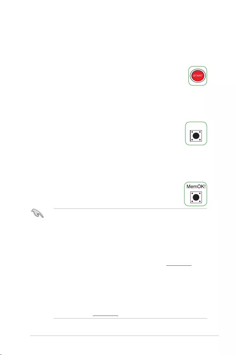
1. Power-on button (START)
The motherboard comes with a power-on button that allows you to power
up or wake up the system. The button also lights up when the system is
plugged to a power source indicating that you should shut down the system
and unplug the power cable before removing or installing any motherboard
component.
2. RESET button (RESET)
Press the reset button to reboot the system.
• TurnoffthesystemandreinstalltheDIMMbeforeusingtheMemOK!function.
• TheMemOK!buttondoesnotfunctionunderWindows® OS environment.
• Duringthetuningprocess,thesystemloadsandtestsfailsafememorysettings.It
takes about 30 seconds for the system to test one set of failsafe settings. If the test
fails, the system reboots and test the next set of failsafe settings.
• Duetomemorytuningrequirement,thesystemautomaticallyrebootswheneach
timing set is tested. If the installed DIMMs still fail to boot after the whole tuning
process,replacetheDIMMswithonesrecommendedintheMemoryQVL(Qualied
Vendors Lists) in this user manual or on the ASUS website at www.asus.com.
• IfyouturnoffthecomputerandreplaceDIMMsduringthetuningprocess,thesystem
continues memory tuning after turning on the computer. To stop memory tuning, turn
off the computer and unplug the power cord for about 5–10 seconds.
• IfyoursystemfailstobootupduetoBIOSoverclocking,presstheMemOK!button
to boot and load the BIOS default settings. A message will appear during POST
reminding you that the BIOS has been restored to its default settings.
• WerecommendthatyoudownloadandupdatetothelatestBIOSversionfromthe
ASUS website at www.asus.com after using the MemOK! function.
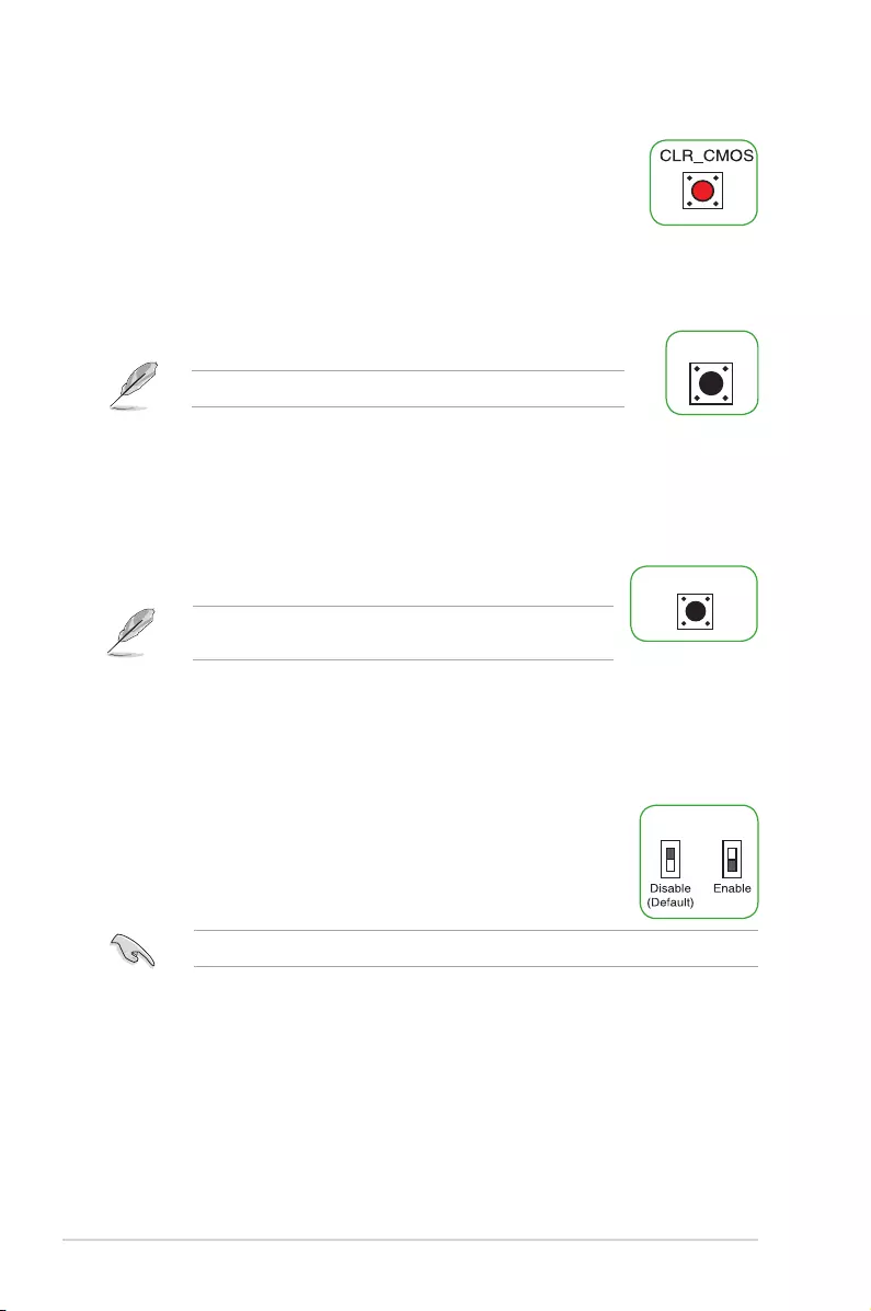
3. MemOK! button (MemOK!)
Installing DIMMs that are not compatible with the motherboard may
cause system boot failure. Press the MemOK! button until the memory
compatibility tuning for successful boot.
1-18 Motherboard Pin Denition
4. Clear CMOS button (CLR_CMOS)
Press this button to clear the BIOS setup information only when the
systems hangs due to overclocking.
5. KeyBot button (KeyBot)
Press this button to activate the KeyBot feature.
The KeyBot feature supports USB keyboards only.
Ensure to set the LN2 Mode jumper to [Enable] before using the Slow Mode switch.
6. Sonic SoundStage button (SOUNDSTAGE)
Press this button to activate the Sonic SoundStage feature.
7. Slow Mode switch
Slow Mode switch allows your system to provide better overclocking
margins when using the LN2 cooling system. When enabled, the
Slow Mode switch prevents the system from crashing, slows down the
CPU, and the system’s tuner will make the adjustments.
The debug code on the Q-Code LED shows the current Sonic
SoundStageprolewhenyoupresstheSonicSoundStagebutton.
ASUS
Loading…
P
- PRIME-B250M-PLUS
- PRIME-B250-PLUS
- PRIME H270M-PLUS/CSM5
- Prime H310I-Plus
- Prime H310I-Plus R2.02
- PRIME H310M2 R2.0/FPT II
- Prime H310M-A R2.02
- Prime H310M-C
- Prime H310M-C R2.0
- Prime H310M-D2
- Prime H310M-D R2.0
- Prime H310M-E2
- PRIME H310M-E/BR
- Prime H310M-E R2.02
- PRIME H310M-E R2.0/BR
- Prime H310M-K R2.02
- PRIME H310M-R R2.02
- Prime H310-Plus R2.0
- Prime H310T
- Prime H370M-Plus2
- Prime H370-Plus
- Prime H410I-Plus
- Prime H410M-A3
- Prime H410M-D2
- Prime H410M-E2
- Prime H410M-K2
- Prime H410M-K R2.0
- PRIME H410M-R2
- Prime H470M-Plus2
- Prime H470-Plus2
- Prime H510M-A
- Prime H510M-D
- Prime H510M-K
- Prime H670 Plus D4
- PRIME J3355I-C
- Prime J4005I-C
- PRIME J4005I-C/BR
- PRIME-Q270M-C2
- PRIME TRX40-PRO
- Prime TRX40-Pro S2
- Prime X299-A
- Prime X299-A II
- Prime X299-Deluxe2
- Prime X299-Deluxe II2
- Prime X299 Edition 30
- prime x370-a
- Prime X370-Pro
- Prime X399-A
- PRIME X470-PRO
- Prime X570-P2
- Prime X570-Pro2
- PRIME Z270-A
- PRIME Z270-AR11
- Prime Z270M-Plus2
- PRIME Z270M-PLUS/BR5
- Prime Z270-P2
- PRIME Z370-A II
- Prime Z370-P
- Prime Z370-P II
- Prime Z390-A4
- Prime Z390M-Plus2
- Prime Z390-P
- Prime Z490-A2
- Prime Z490M-Plus2
- Prime Z490-P2
- Prime Z490-V2
- Prime Z590-A
- Prime Z590-P
- Prime Z590-P Wi-Fi
- Prime Z690-A
- Prime Z690M Plus DDR4
- Prime Z690-P
- Prime Z690-P D4
- Prime Z690-P WiFi DDR4
- PRL-DL
- PRL-DLS
- PRL-DLS533
- PRO 2300
- PRO 3227
- PRO 35
- PRO 362
- PRO 36S22
- PRO 521
- PRO 721
- PRO 818
- Pro A520M-C2
- Pro B460M-C2
- PRO B53A
- Pro D641SC-I39100030R
- Pro E500 G6
- PRO H310M-R R2.0 WI-FI
- PRO H310M-R R2.0 WI-FI/CSM
- Pro H410M-C2
- Pro H410T2
- Pro P1440FA-FA1476R
- Pro P1510CJA-BQ418R
- Pro Q470M-C
- Pro Q470M-C/CSM
- Pro WS 621-64L SAGE
- Pro WS C246-Ace
Loading…
Loading…
Nothing found
Prime Z270-P
operation manual
86 pgs6.3 Mb0
Service Manual [de]
86 pgs4.17 Mb0
Table of contents
Loading…
…
ASUS operation manual
Download
Specifications and Main Features
Frequently Asked Questions
User Manual


Loading…
+ 60 hidden pages
You need points to download manuals.
1 point = 1 manual.
You can buy points or you can get point for every manual you upload.
Buy points
Upload your manuals
-
Драйверы
34
-
Инструкции по эксплуатации
9
Языки:
ASUS PRIME Z270-P инструкция по эксплуатации
(18 страниц)
- Языки:Английский
-
Тип:
PDF -
Размер:
1.55 MB -
Описание:
E11133_MB_Pin_Definition Manual(English)
Просмотр
ASUS PRIME Z270-P инструкция по эксплуатации
(11 страниц)
- Языки:Английский
-
Тип:
PDF -
Размер:
1.6 MB -
Описание:
BIOS_Update_E-Manual(English)
Просмотр
ASUS PRIME Z270-P инструкция по эксплуатации
(86 страниц)
- Языки:Французский
-
Тип:
PDF -
Размер:
4.03 MB -
Описание:
PRIME Z270-P User’s manual ( FRENCH )
PRIME Z270-P User’s manual ( FRENCH )
Просмотр
ASUS PRIME Z270-P инструкция по эксплуатации
(18 страниц)
- Языки:Китайский
-
Тип:
PDF -
Размер:
1.68 MB -
Описание:
C11133_MB_PIN_DEFINITION Manual(Simplified Chinese)
Просмотр
ASUS PRIME Z270-P инструкция по эксплуатации
(18 страниц)
- Языки:Японский
-
Тип:
PDF -
Размер:
1.59 MB -
Описание:
J11133_MB_Pin_Definition Manual(Japanese)
Просмотр
ASUS PRIME Z270-P инструкция по эксплуатации
(18 страниц)
- Языки:Китайский
-
Тип:
PDF -
Размер:
1.73 MB -
Описание:
T11133_mb_pin_definition_manual(Traditional Chinese)
Просмотр
ASUS PRIME Z270-P инструкция по эксплуатации
(11 страниц)
- Языки:Японский
-
Тип:
PDF -
Размер:
1.13 MB -
Описание:
BIOS_Update_E-Manual(Japanese)
Просмотр
ASUS PRIME Z270-P инструкция по эксплуатации
(11 страниц)
- Языки:Китайский
-
Тип:
PDF -
Размер:
1.72 MB -
Описание:
BIOS_Update_E-Manual(Traditional Chinese)
Просмотр
ASUS PRIME Z270-P инструкция по эксплуатации
(16 страниц)
-
Тип:
PDF -
Размер:
1.21 MB -
Описание:
DF172_200_Series_Ai_Suite_3_Guide
Просмотр
На NoDevice можно скачать инструкцию по эксплуатации для ASUS PRIME Z270-P. Руководство пользователя необходимо для ознакомления с правилами установки и эксплуатации ASUS PRIME Z270-P. Инструкции по использованию помогут правильно настроить ASUS PRIME Z270-P, исправить ошибки и выявить неполадки.