

P8H61-M LX2
Motherboard

E6775
Revised Edition
July 2011
Copyright © 2011 ASUSTeK Computer Inc. All Rights Reserved.
No part of this manual, including the products and software described in it, may be reproduced,
transmitted, transcribed, stored in a retrieval system, or translated into any language in any form or by any
means, except documentation kept by the purchaser for backup purposes, without the express written
permission of ASUSTeK Computer Inc. (“ASUS”).
Product warranty or service will not be extended if: (1) the product is repaired, modied or altered, unless
such repair, modication of alteration is authorized in writing by ASUS; or (2) the serial number of the
product is defaced or missing.
ASUS PROVIDES THIS MANUAL “AS IS” WITHOUT WARRANTY OF ANY KIND, EITHER EXPRESS
OR IMPLIED, INCLUDING BUT NOT LIMITED TO THE IMPLIED WARRANTIES OR CONDITIONS OF
MERCHANTABILITY OR FITNESS FOR A PARTICULAR PURPOSE. IN NO EVENT SHALL ASUS, ITS
DIRECTORS, OFFICERS, EMPLOYEES OR AGENTS BE LIABLE FOR ANY INDIRECT, SPECIAL,
INCIDENTAL, OR CONSEQUENTIAL DAMAGES (INCLUDING DAMAGES FOR LOSS OF PROFITS,
LOSS OF BUSINESS, LOSS OF USE OR DATA, INTERRUPTION OF BUSINESS AND THE LIKE),
EVEN IF ASUS HAS BEEN ADVISED OF THE POSSIBILITY OF SUCH DAMAGES ARISING FROM ANY
DEFECT OR ERROR IN THIS MANUAL OR PRODUCT.
SPECIFICATIONS AND INFORMATION CONTAINED IN THIS MANUAL ARE FURNISHED FOR
INFORMATIONAL USE ONLY, AND ARE SUBJECT TO CHANGE AT ANY TIME WITHOUT NOTICE,
AND SHOULD NOT BE CONSTRUED AS A COMMITMENT BY ASUS. ASUS ASSUMES NO
RESPONSIBILITY OR LIABILITY FOR ANY ERRORS OR INACCURACIES THAT MAY APPEAR IN THIS
MANUAL, INCLUDING THE PRODUCTS AND SOFTWARE DESCRIBED IN IT.
Products and corporate names appearing in this manual may or may not be registered trademarks or
copyrights of their respective companies, and are used only for identication or explanation and to the
owners’ benet, without intent to infringe.
Offer to Provide Source Code of Certain Software
This product may contain copyrighted software that is licensed under the General Public License (“GPL”)
and under the Lesser General Public License Version (“LGPL”). The GPL and LGPL licensed code in this
product is distributed without any warranty. Copies of these licenses are included in this product.
You may obtain the complete corresponding source code (as dened in the GPL) for the GPL Software,
and/or the complete corresponding source code of the LGPL Software (with the complete machinereadable “work that uses the Library”) for a period of three years after our last shipment of the product
including the GPL Software and/or LGPL Software, which will be no earlier than December 1, 2011, either
(1) for free by downloading it from http://support.asus.com/download;
or
(2) for the cost of reproduction and shipment, which is dependent on the preferred carrier and the location
where you want to have it shipped to, by sending a request to:
ASUSTeK Computer Inc.
Legal Compliance Dept.
15 Li Te Rd.,
Beitou, Taipei 112
Taiwan
In your request please provide the name, model number and version, as stated in the About Box of the
product for which you wish to obtain the corresponding source code and your contact details so that we
can coordinate the terms and cost of shipment with you.
The source code will be distributed WITHOUT ANY WARRANTY and licensed under the same license as
the corresponding binary/object code.
This offer is valid to anyone in receipt of this information.
ASUSTeK is eager to duly provide complete source code as required under various Free Open Source
Software licenses. If however you encounter any problems in obtaining the full corresponding source code
we would be much obliged if you give us a notication to the email address gpl@asus.com, stating the
product and describing the problem (please do NOT send large attachments such as source code archives
etc to this email address).
ii

Contents
Notices …………………………………………………………………………………………… vi
Safety information …………………………………………………………………………. vii
About this guide …………………………………………………………………………… viii
P8H61-M LX2 specications summary …………………………………………….. ix
Chapter 1: Product introduction
1.1 Before you proceed …………………………………………………………… 1-1
1.2 Motherboard overview ……………………………………………………….. 1-2
1.2.1 Placement direction ……………………………………………….. 1-2
1.2.2 Screw holes ………………………………………………………….. 1-2
1.2.3 Motherboard layout ………………………………………………… 1-3
1.2.4 Layout contents ……………………………………………………… 1-3
1.3 Central Processing Unit (CPU) …………………………………………… 1-4
1.3.1 Installing the CPU ………………………………………………….. 1-4
1.3.2 Installing the CPU heatsink and fan ………………………….. 1-7
1.3.3 Uninstalling the CPU heatsink and fan ……………………… 1-8
1.4 System memory ………………………………………………………………… 1-9
1.4.1 Overview ………………………………………………………………. 1-9
1.4.2 Memory congurations ………………………………………….. 1-10
1.4.3 Installing a DIMM …………………………………………………. 1-13
1.4.4 Removing a DIMM ……………………………………………….. 1-13
1.5 Expansion slots ……………………………………………………………….. 1-14
1.5.1 Installing an expansion card ………………………………….. 1-14
1.5.2 Conguring an expansion card ………………………………. 1-14
1.5.3 PCI slot ………………………………………………………………. 1-14
1.5.4 PCI Express x1 slot ………………………………………………. 1-14
1.5.5 PCI Express x16 slot …………………………………………….. 1-14
1.6 Jumpers ………………………………………………………………………….. 1-15
1.7 Connectors ……………………………………………………………………… 1-16
1.7.1 Rear panel connectors ………………………………………….. 1-16
1.7.2 Internal connectors ………………………………………………. 1-17
1.8 Software support ……………………………………………………………… 1-22
1.8.1 Installing an operating system ……………………………….. 1-22
1.8.2 Support DVD information ………………………………………. 1-22
iii

Contents
Chapter 2: BIOS information
2.1 Managing and updating your BIOS …………………………………….. 2-1
2.1.1 ASUS Update utility ……………………………………………….. 2-1
2.1.2 ASUS EZ Flash 2 …………………………………………………… 2-2
2.1.3 ASUS CrashFree BIOS 3 utility ……………………………….. 2-3
2.1.4 ASUS BIOS Updater ………………………………………………. 2-4
2.2 BIOS setup program ………………………………………………………….. 2-7
2.3 Main menu ………………………………………………………………………. 2-11
2.3.1 System Language [English] …………………………………….2-11
2.3.2 System Date [Day xx/xx/xxxx] ………………………………….2-11
2.3.3 System Time [xx:xx:xx] …………………………………………..2-11
2.3.4 Security ………………………………………………………………..2-11
2.4 Ai Tweaker menu ……………………………………………………………… 2-13
2.4.1 Memory Frequency [Auto] ……………………………………… 2-13
2.4.2 iGPU Max. Frequency [Auto] …………………………………. 2-14
2.4.3 GPU Boost [OK] …………………………………………………… 2-14
2.4.4 DRAM Timing Control …………………………………………… 2-14
2.4.5 CPU Power Management ……………………………………… 2-14
2.5 Advanced menu ………………………………………………………………. 2-15
2.5.1 CPU Conguration ……………………………………………….. 2-16
2.5.2 System Agent Conguration ………………………………….. 2-17
2.5.3 PCH Conguration ……………………………………………….. 2-17
2.5.4 SATA Conguration ………………………………………………. 2-17
2.5.5 USB Conguration ……………………………………………….. 2-18
2.5.6 Onboard Devices Conguration ……………………………… 2-19
2.5.7 APM …………………………………………………………………… 2-19
2.6 Monitor menu ………………………………………………………………….. 2-21
2.6.1 CPU Temperature / MB Temperature [xxxºC/xxxºF] …… 2-21
2.6.2 CPU / Chassis Fan Speed …………………………………….. 2-21
2.6.3 CPU Q-Fan Control [Enabled] ……………………………….. 2-21
2.6.4 Chassis Q-Fan Control [Enabled] …………………………… 2-22
2.6.5 CPU Voltage, 3.3V Voltage, 5V Voltage, 12V Voltage .. 2-23
2.6.6 Anti Surge Support [Enabled] ………………………………… 2-23
iv

Contents
2.7 Boot menu ………………………………………………………………………. 2-24
2.7.1 Bootup NumLock State [On] ………………………………….. 2-24
2.7.2 Full Screen Logo [Enabled] ……………………………………. 2-24
2.7.3 Wait for ‘F1’ If Error [Enabled] ………………………………… 2-24
2.7.4 Option ROM Messages [Force BIOS] ……………………… 2-25
2.7.5 Setup Mode [EZ Mode] …………………………………………. 2-25
2.7.6 Boot Option Priorities ……………………………………………. 2-25
2.7.7 Boot Override ………………………………………………………. 2-25
2.8 Tools menu ……………………………………………………………………… 2-26
2.8.1 ASUS EZ Flash Utility …………………………………………… 2-26
2.8.2 ASUS SPD Information …………………………………………. 2-26
2.8.3 ASUS O.C. Prole ………………………………………………… 2-26
2.9 Exit menu ………………………………………………………………………… 2-27
v
Notices
Federal Communications Commission Statement
This device complies with Part 15 of the FCC Rules. Operation is subject to the following two
conditions:
• This device may not cause harmful interference, and
• This device must accept any interference received including interference that may cause
undesired operation.
This equipment has been tested and found to comply with the limits for a Class B digital
device, pursuant to Part 15 of the FCC Rules. These limits are designed to provide
reasonable protection against harmful interference in a residential installation. This
equipment generates, uses and can radiate radio frequency energy and, if not installed
and used in accordance with manufacturer’s instructions, may cause harmful interference
to radio communications. However, there is no guarantee that interference will not occur
in a particular installation. If this equipment does cause harmful interference to radio or
television reception, which can be determined by turning the equipment off and on, the user
is encouraged to try to correct the interference by one or more of the following measures:
•
Reorient or relocate the receiving antenna.
•
Increase the separation between the equipment and receiver.
•
Connect the equipment to an outlet on a circuit different from that to which the receiver is
connected.
•
Consult the dealer or an experienced radio/TV technician for help.
The use of shielded cables for connection of the monitor to the graphics card is required
to assure compliance with FCC regulations. Changes or modications to this unit not
expressly approved by the party responsible for compliance could void the user’s authority
to operate this equipment.
Canadian Department of Communications Statement
This digital apparatus does not exceed the Class B limits for radio noise emissions from
digital apparatus set out in the Radio Interference Regulations of the Canadian Department
of Communications.
This class B digital apparatus complies with Canadian ICES-003.
ASUS Recycling/Takeback Services
ASUS recycling and takeback programs come from our commitment to the highest standards
for protecting our environment. We believe in providing solutions for you to be able to
responsibly recycle our products, batteries, other components as well as the packaging
materials. Please go to http://csr.asus.com/english/Takeback.htm for the detailed recycling
information in different regions.
vi
REACH
Complying with the REACH (Registration, Evaluation, Authorisation, and Restriction of
Chemicals) regulatory framework, we published the chemical substances in our products at
ASUS REACH website at http://csr.asus.com/english/REACH.htm.
DO NOT throw the motherboard in municipal waste. This product has been designed to
enable proper reuse of parts and recycling. This symbol of the crossed out wheeled bin
indicates that the product (electrical and electronic equipment) should not be placed in
municipal waste. Check local regulations for disposal of electronic products.
DO NOT throw the mercury-containing button cell battery in municipal waste. This symbol
of the crossed out wheeled bin indicates that the battery should not be placed in municipal
waste.
Safety information
Electrical safety
• To prevent electric shock hazard, disconnect the power cable from the electric outlet
before relocating the system.
• When adding or removing devices to or from the system, ensure that the power cables
for the devices are unplugged before the signal cables are connected. If possible,
disconnect all power cables from the existing system before you add a device.
• Before connecting or removing signal cables from the motherboard, ensure that all
power cables are unplugged.
• Seek professional assistance before using an adapter or extension cord. These devices
could interrupt the grounding circuit.
• Ensure that your power supply is set to the correct voltage in your area. If you are not
sure about the voltage of the electrical outlet you are using, contact your local power
company.
• If the power supply is broken, do not try to x it by yourself. Contact a qualied service
technician or your retailer.
Operation safety
•
Before installing the motherboard and adding devices on it, carefully read all the manuals
that came with the package.
•
Before using the product, ensure that all cables are correctly connected and the power
cables are not damaged. If you detect any damage, contact your dealer immediately.
•
To avoid short circuits, keep paper clips, screws, and staples away from connectors,
slots, sockets and circuitry.
•
Avoid dust, humidity, and temperature extremes. Do not place the product in any area
where it may become wet.
•
Place the product on a stable surface.
•
If you encounter technical problems with the product, contact a qualied service
technician or your retailer.
vii
About this guide
This user guide contains the information you need when installing and conguring the
motherboard.
How this guide is organized
This guide contains the following parts:
• Chapter 1: Product introduction
This chapter describes the features of the motherboard and the new technology it
supports.
• Chapter 2: BIOS information
This chapter tells how to change system settings through the BIOS Setup menus.
Detailed descriptions of the BIOS parameters are also provided.
Conventions used in this guide
To ensure that you perform certain tasks properly, take note of the following symbols used
throughout this manual.
DANGER/WARNING: Information to prevent injury to yourself when trying to
complete a task.
CAUTION: Information to prevent damage to the components when trying to
complete a task.
IMPORTANT: Instructions that you MUST follow to complete a task.
NOTE: Tips and additional information to help you complete a task.
Where to nd more information
Refer to the following sources for additional information and for product and software
updates.
1. ASUS websites
The ASUS website provides updated information on ASUS hardware and software
products. Refer to the ASUS contact information.
2. Optional documentation
Your product package may include optional documentation, such as warranty yers,
that may have been added by your dealer. These documents are not part of the
standard package.
Typography
Bold text Indicates a menu or an item to select.
Italics
Used to emphasize a word or a phrase.
<Key> Keys enclosed in the less-than and greater-than sign means
that you must press the enclosed key.
Example: <Enter> means that you must press the Enter or
Return key.
<Key1>+<Key2>+<Key3> If you must press two or more keys simultaneously, the key
names are linked with a plus sign (+).
Example: <Ctrl>+<Alt>+<D>
viii
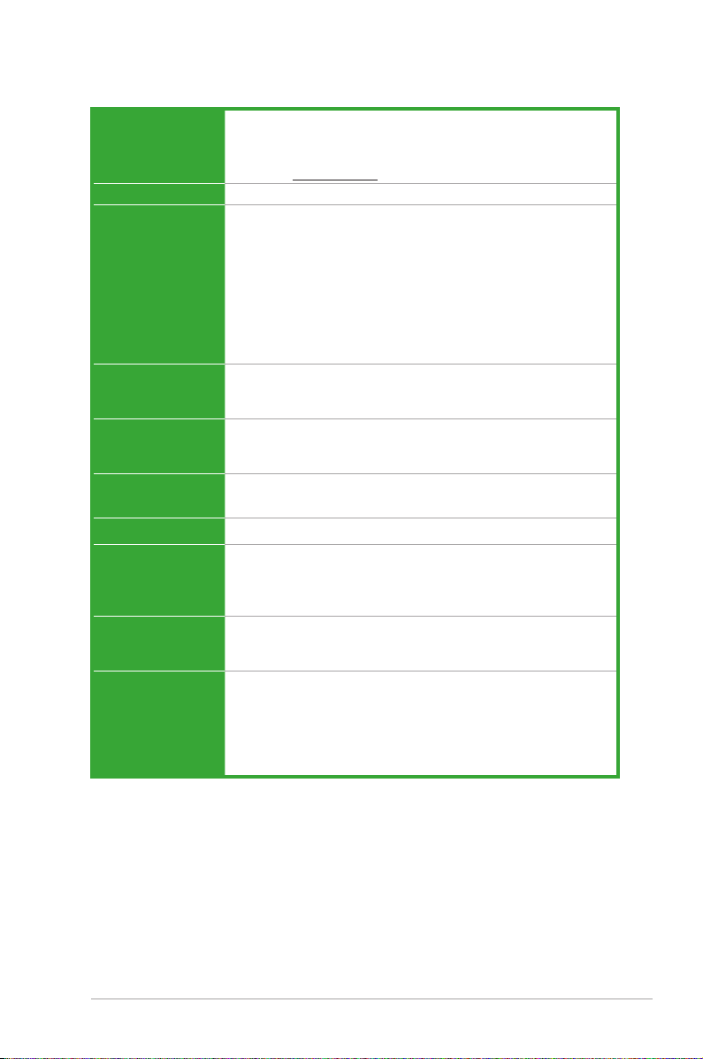
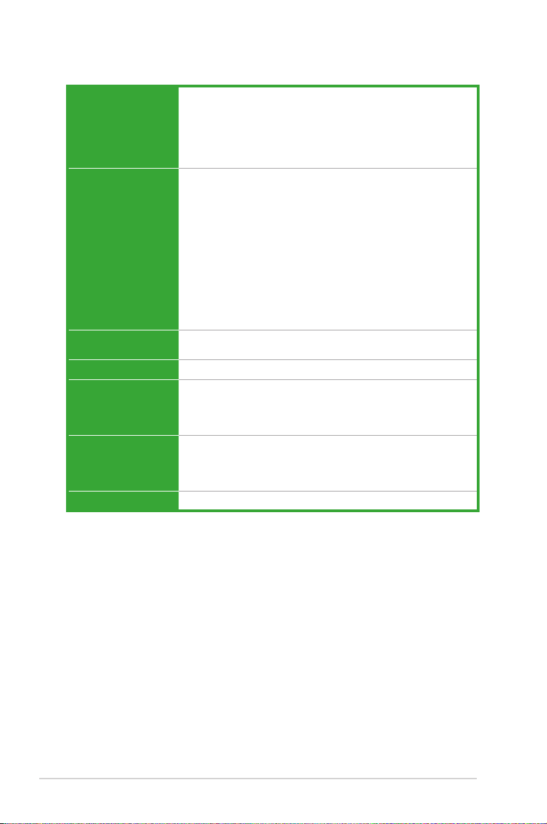
P8H61-M LX2 specications summary
CPU LGA1155 socket for Intel® Second Generation processors
Chipset Intel® H61 Express Chipset
Memory 2 x DIMM, max. 8GB, DDR3 1333 / 1066 MHz, non-ECC,
Graphics Dual independent displays support: DVI-D and D-Sub
Expansion slots 1 x PCI Express 2.0 x16 slot
Storage
LAN
Audio VIA® VT1708S 8-channel* High Denition Audio CODEC
USB Intel® H61 Express Chipset:
ASUS unique
features
Supports 32nm CPU
Supports Enhanced Intel® SpeedStep Technology (EIST)
* Refer to www.asus.com for Intel® CPU support list.
un-buffered memory
Dual-channel memory architecture
* Refer to www.asus.com for the latest Memory QVL (Qualied
Vendors List).
** When you install a total memory of 4GB capacity or more,
Windows® 32-bit operating system may only recognize less
than 3GB. We recommend a maximum of 3GB system memory
if you are using a Windows® 32-bit operating system.
Supports DVI with max. resolution up to 1920×1200 @60Hz
Supports D-Sub with max. resolution up to 2048×1536 @75Hz
2 x PCI Express 2.0 x1 slots
1 x PCI slot
Intel® H61 Express Chipset:
— 4 x Serial ATA 3.0 Gb/s connectors
Realtek® 8111E PCIe Gigabit LAN controller
— Supports Multi-Streaming
* Use a chassis with HD audio module in the front panel to
support an 8-channel audio output.
— 10 x USB 2.0/1.1 ports (4 ports at the mid-board, 6 ports at
the back panel)
GPU Boost
ASUS Anti-Surge Protection
ASUS EFI BIOS
ASUS CrashFree BIOS 3
ASUS EZ Flash 2
ASUS MyLogo 2™
(continued on the next page)
ix
P8H61-M LX2 specications summary
Rear panel ports 1 x PS/2 keyboard / mouse combo port
Internal connectors/
switches/ buttons
BIOS features 32 Mb Flash ROM, EFI BIOS, PnP, DMI v2.0, WfM 2.0,
Manageability
Accessories 2 x Serial ATA 3.0Gb/s cables
Support DVD Drivers
Form factor
1 x DVI-D port
1 x D-Sub port
1 x LAN (RJ-45) port
6 x USB 2.0/1.1 ports
3 x Audio jacks
2 x USB 2.0/1.1 connectors support additional 4 USB 2.0/1.1
ports
4 x SATA 3.0 Gb/s connectors
1 x CPU fan connector
1 x Chassis fan connector
1 x Front panel audio connector
1 x S/PDIF Out connector
1 x COM connector
1 x System panel connector
1 x Speaker connector
1 x 24-pin ATX power connector
1 x 4-pin ATX 12V power connector
ACPI v2.0a, SM BIOS v2.6, Multi-language BIOS
WOL, PXE, PME Wake Up, WOR by Ring
1 x I/O shield
1 x User Manual
1 x Support DVD
ASUS utilities
ASUS Update
Anti-virus software (OEM version)
MicroATX form factor: 9.6 in x 7.8 in (24.4 cm x 19.8 cm)
* Specications are subject to change without notice.
x
Chapter 1
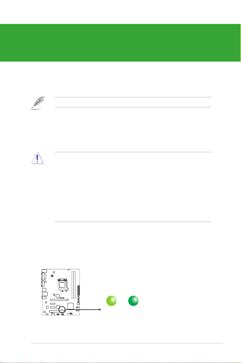
SB_PWR
ON
Standby Power Powered Off
OFF
P8H61-M LX2
P8H61-M LX2 Onboard LED
Product introduction
Thank you for buying an ASUS® P8H61-M LX2 motherboard!
Before you start installing the motherboard, and hardware devices on it, check the items in
your motherboard package. Refer to page x for the list of accessories.
If any of the items is damaged or missing, contact your retailer.
1.1 Before you proceed
Take note of the following precautions before you install motherboard components or change
any motherboard settings.
• Unplug the power cord from the wall socket before touching any component.
• Before handling components, use a grounded wrist strap or touch a safely grounded
object or a metal object, such as the power supply case, to avoid damaging them due to
static electricity.
• Hold components by the edges to avoid touching the ICs on them.
• Whenever you uninstall any component, place it on a grounded antistatic pad or in the
bag that came with the component.
• Before you install or remove any component, ensure that the ATX power supply is
switched off or the power cord is detached from the power supply. Failure to do so may
cause severe damage to the motherboard, peripherals, or components.
Standby Power LED
The motherboard comes with a standby power LED that lights up to indicate that the system
is ON, in sleep mode, or in soft-off mode. This is a reminder that you should shut down
the system and unplug the power cable before removing or plugging in any motherboard
component. The illustration below shows the location of the onboard LED.
1-1Chapter 1: Product introduction
1.2 Motherboard overview
Before you install the motherboard, study the conguration of your chassis to ensure that the
motherboard ts into it.
Ensure that you unplug the power cord before installing or removing the motherboard.
Failure to do so can cause you physical injury and damage motherboard components.
1.2.1 Placement direction
When installing the motherboard, ensure that you place it into the chassis in the correct
orientation. The edge with external ports goes to the rear part of the chassis as indicated in
the image below.
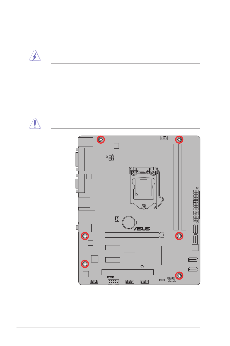
1.2.2 Screw holes
Place six screws into the holes indicated by circles to secure the motherboard to the chassis.
Do not overtighten the screws! Doing so can damage the motherboard.
Place this side towards
the rear of the chassis
ASUS P8H61-M LX21-2
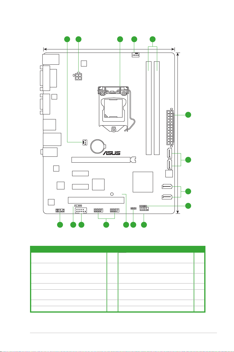
1.2.3 Motherboard layout
P8H61-M LX2
PCIEX16_1
PCI1
PCIEX1_1
PCIEX1_2
COM1
USB910
F_PANEL
SPEAKER
USB78
C
LR
T
C
AAFP
ATX12V
EATXPWR
CPU_FAN
CHA_FAN
Lithium Cell
CMOS Power
Super
I/O
VIA
VT1708S
RTL
8111E
EPU
ASM
1442
32Mb
BIOS
asmedia
ASM1083
SB_PWR
SPDIF_OUT
24.4cm(9.6in)
LGA1155
Intel
®
H61
DDR3 DIMM_A1 (64bit, 240-pin module)
DDR3 DIMM_B1 (64bit, 240-pin module)
SATA3G_3
SATA3G_4
SATA3G_2
SATA3G_1
AUDIO
KB_USB56
LAN1_USB12
USB34
19.8cm(7.8in)
VGA
DVI
321 41
5
2
7810111213 9
5
6
1.2.4 Layout contents
Connectors/Jumpers/Slots/LED Page Connectors/Jumpers/Slots/LED Page
1. CPU and chassis fan connectors
(4-pin CPU_FAN, 3-pin CHA_FAN)
2. ATX power connectors (24-pin EATXPWR,
4-pin ATX12V)
3. Intel® LGA1155 CPU socket 1-4 10. USB connectors (10-1 pin USB78, USB910) 1-19
4. DDR3 DIMM slots 1-9 11. Serial port connector (10-1 pin COM1) 1-18
5. Intel® H61 Serial ATA 3.0Gb/s connectors
6. Speaker connector (4-pin SPEAKER) 1-21 13. Front panel audio connector (10-1 pin AAFP) 1-17
7. System panel connector (10-1 pin PANEL) 1-21
(7-pin SATA3G_1/2/3/4)
1-19 8. Clear RTC RAM (3-pin CLRTC) 1-15
1-18 9. Standby power LED (SB_PWR) 1-1
1-20 12. Digital audio connector (4-1 pin SPDIF_OUT) 1-20
1-3Chapter 1: Product introduction
1.3 Central Processing Unit (CPU)
P8H61-M LX2
P8H61-M LX2 CPU socket LGA1155
The motherboard comes with a surface mount LGA1155 socket designed for the Intel®
Second Generation processors.
• Refer to www.asus.com for Intel® CPU support list.
• Unplug all power cables before installing the CPU.
• Upon purchase of the motherboard, ensure that the PnP cap is on the socket and the
socket contacts are not bent. Contact your retailer immediately if the PnP cap is missing,
or if you see any damage to the PnP cap/socket contacts/motherboard components.
ASUS will shoulder the cost of repair only if the damage is shipment/transit-related.
• Keep the cap after installing the motherboard. ASUS will process Return Merchandise
Authorization (RMA) requests only if the motherboard comes with the cap on the
LGA1155 socket.
• The product warranty does not cover damage to the socket contacts resulting from
incorrect CPU installation/removal, or misplacement/loss/incorrect removal of the PnP
cap.
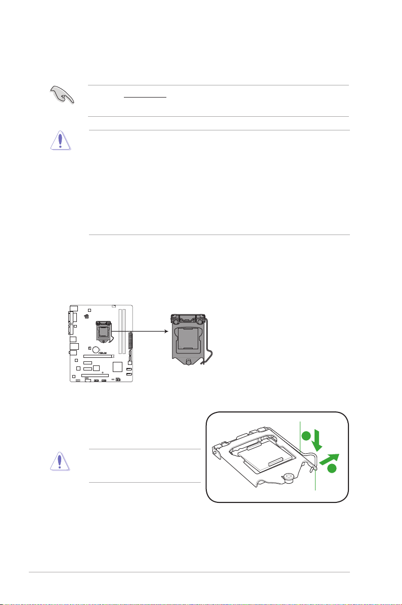
1.3.1 Installing the CPU
To install a CPU:
1. Locate the CPU socket on the motherboard.
2. Press the load lever with your thumb (A),
and then move it to the right (B) until it is
released from the retention tab.
To prevent damage to the socket pins,
do not remove the PnP cap unless
you are installing a CPU.
Load lever
Retention tab
ASUS P8H61-M LX21-4
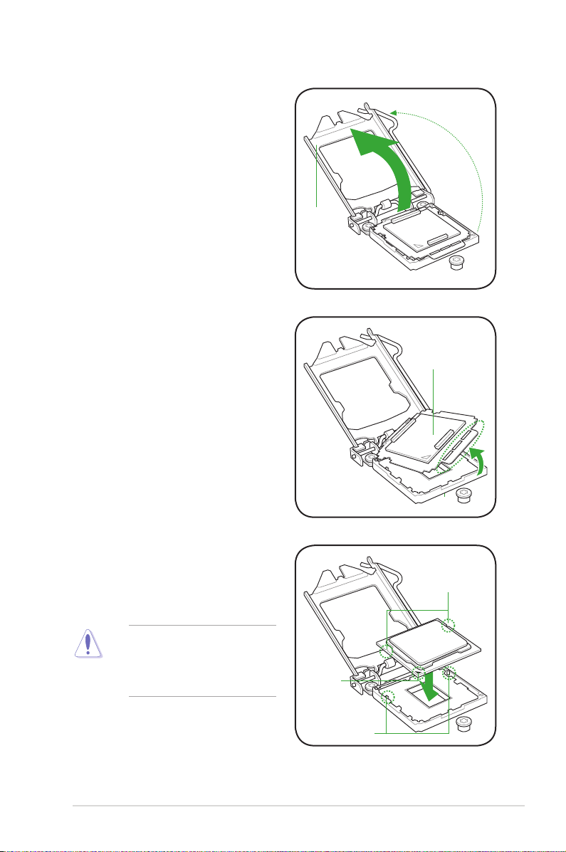
3. Lift the load lever in the direction of the
arrow until the load plate is completely
lifted.
4. Remove the PnP cap from the CPU
socket by lifting the tab only.
Load plate
PnP cap
5. Position the CPU over the socket,
ensuring that the gold triangle is on the
bottom-left corner of the socket, and
then t the socket alignment keys into
the CPU notches.
The CPU ts in only one correct
orientation. DO NOT force the CPU
into the socket to prevent bending
the connectors on the socket and
damaging the CPU!
CPU notches
Gold
triangle
mark
Alignment keys
1-5Chapter 1: Product introduction
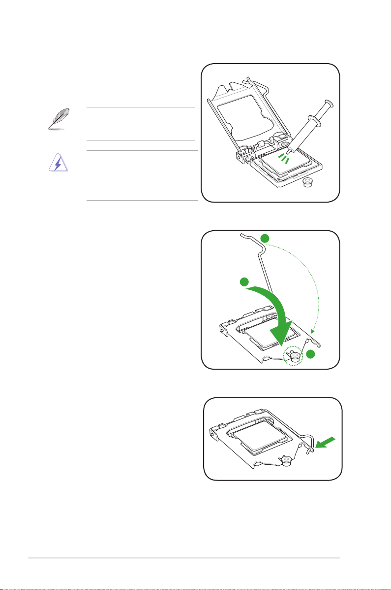
6. Apply some Thermal Interface Material
to the exposed area of the CPU that the
heatsink will be in contact with, ensuring
that it is spread in an even thin layer.
Some heatsinks come with preapplied thermal paste. If so, skip this
step.
The Thermal Interface Material is
toxic and inedible. DO NOT eat it. If
it gets into your eyes or touches your
skin, wash it off immediately, and seek
professional medical help.
7. Close the load plate (A), and then push
down the load lever (B), ensuring that
the front edge of the load plate slides
under the retention knob (C).
8. Insert the load lever under the retention
tab.
ASUS P8H61-M LX21-6
1.3.2 Installing the CPU heatsink and fan
The Intel® LGA1155 processor requires a specially designed heatsink and fan assembly to
ensure optimum thermal condition and performance.
•
When you buy a boxed Intel® processor, the package includes the CPU fan and
heatsink assembly. If you buy a CPU separately, ensure that you use only Intel®-certied
multi-directional heatsink and fan.
• Your Intel® LGA1155 heatsink and fan assembly comes in a push-pin design and
requires no tool to install.
• Use an LGA1155-compatible CPU heatsink and fan assembly only. The LGA1155 socket
is incompatible with the LGA775 and LGA1366 sockets in size and dimension.
If you purchased a separate CPU heatsink and fan assembly, ensure that you have
properly applied Thermal Interface Material to the CPU heatsink or CPU before you install
the heatsink and fan assembly.
Ensure that you have installed the motherboard to the chassis before you install the CPU
fan and heatsink assembly.
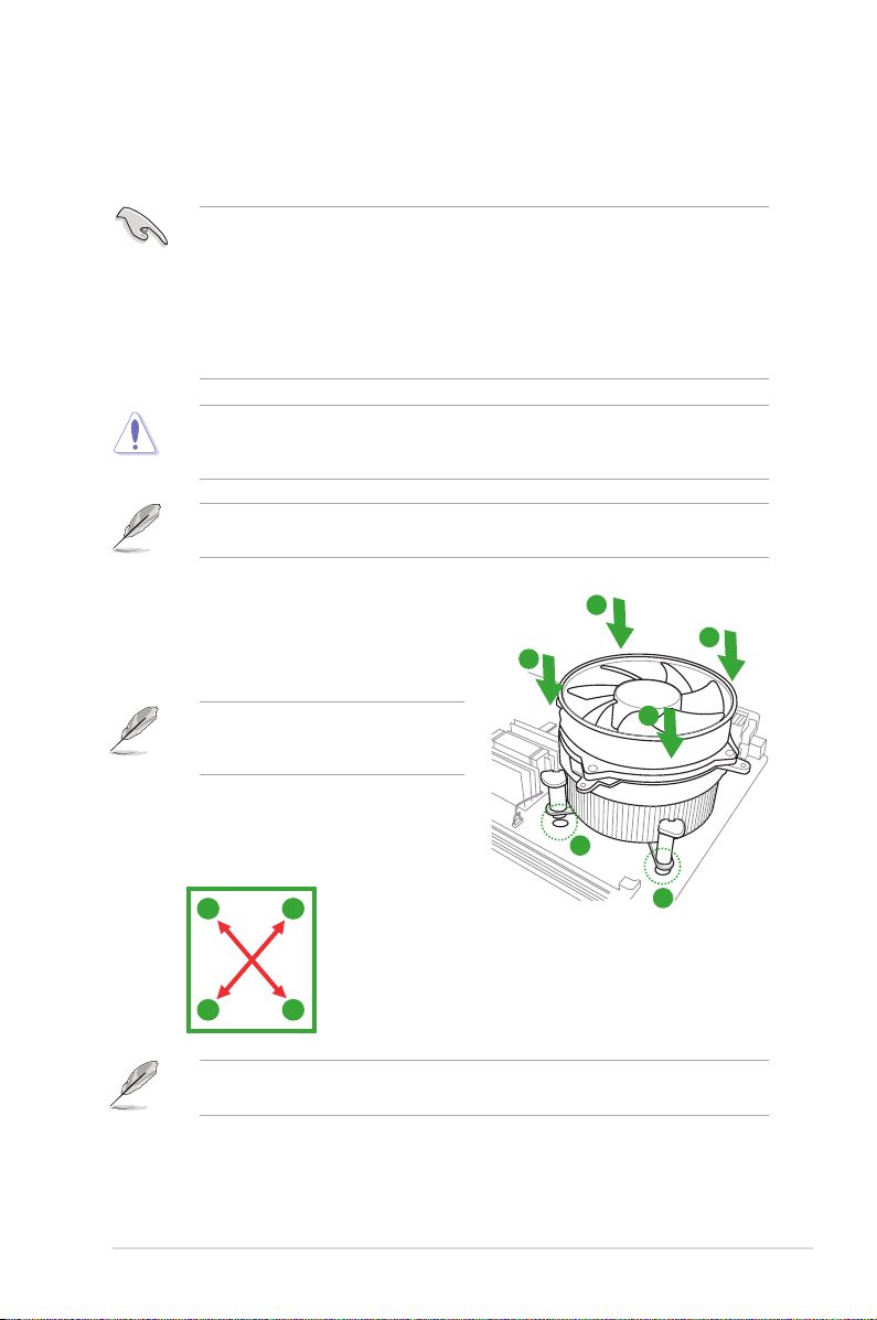
To install the CPU heatsink and fan:
1. Place the heatsink on top of the installed
CPU, ensuring that the four fasteners match
the holes on the motherboard.
Orient the heatsink and fan assembly
such that the CPU fan cable is closest to
the CPU fan connector.
2. Push down two fasteners at a time in a
diagonal sequence to secure the heatsink
and fan assembly in place.
A
B
The type of CPU heatsink and fan assembly may differ, but the installation steps and
functions should remain the same. The illustration above is for reference only.
B
A
A
B
B
A
1
1
1-7Chapter 1: Product introduction
3. Connect the CPU fan cable to the connector on the motherboard labeled CPU_FAN.
CPU_FAN
CPU FAN PWM
CPU FAN IN
CPU FAN PWR
GND
P8H61-M LX2
P8H61-M LX2 CPU fan connector
Do not forget to connect the CPU fan connector! Hardware monitoring errors can occur if
you fail to plug this connector.
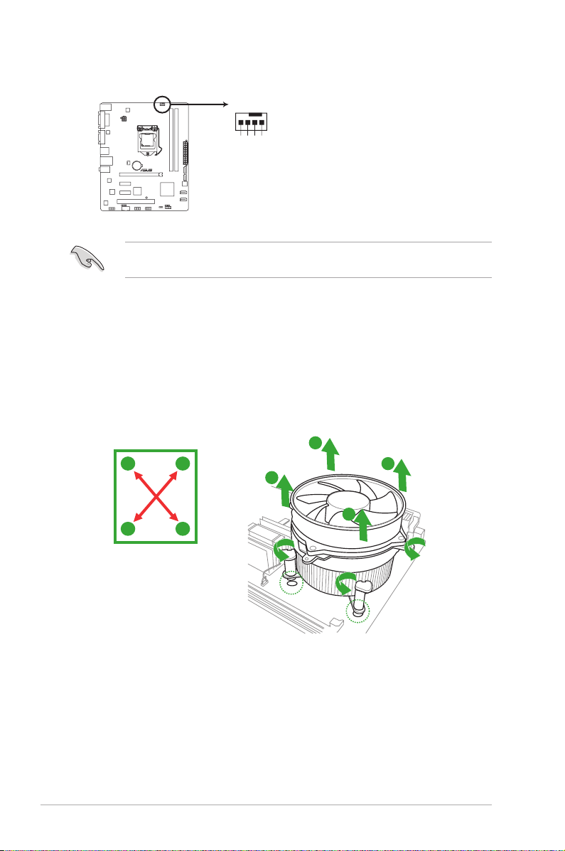
1.3.3 Uninstalling the CPU heatsink and fan
To uninstall the CPU heatsink and fan:
1. Disconnect the CPU fan cable from the connector on the motherboard.
2. Rotate each fastener counterclockwise.
3. Pull up two fasteners at a time in a diagonal sequence to disengage the heatsink and
fan assembly from the motherboard.
A
A
B
B
B
B
A
A
ASUS P8H61-M LX21-8

P8H61-M LX2
P8H61-M LX2 240-pin DDR3 DIMM sockets
DIMM_A1
DIMM_B1
4. Carefully remove the heatsink and fan
assembly from the motherboard.
5. Rotate each fastener clockwise to ensure
correct orientation when reinstalling.
1.4 System memory
1.4.1 Overview
The motherboard comes with two Double Data Rate 3 (DDR3) Dual Inline Memory Modules
(DIMM) sockets.
A DDR3 module has the same physical dimensions as a DDR2 DIMM but is notched
differently to prevent installation on a DDR2 DIMM socket. DDR3 modules are developed for
better performance with less power consumption.
The gure illustrates the location of the DDR3 DIMM sockets:
Channel Sockets
Channel A DIMM_A1
Channel B DIMM_B1
1-9Chapter 1: Product introduction
Loading…
Manuals.eu
- Manuals.eu
- ASUS
- Computers & Peripherals
- Motherboards
- LGA1155
- P8H61-M LX2
- User’s Manual (English)
×
1
2
3
4
5
6
7
8
9
10
11
12
13
14
15
16
17
18
19
20
21
22
23
24
25
26
27
28
29
30
31
32
33
34
35
36
37
38
39
40
41
42
43
44
45
46
47
48
49
50
51
52
53
54
55
56
57
58
59
60
61
⟨
⟩
Copyright © Manuals.eu
Agreement
Privacy Policy
Contact us
- Topics
- manualsbase, manuals,
- Collection
- manuals_asus; manuals; additional_collections
- Language
- English
- Item Size
- 40.1M
- Addeddate
- 2020-06-28 21:47:06
- Collection_added
-
manuals
additional_collections
- Identifier
- manualsbase-id-78682
- Identifier-ark
- ark:/13960/t1mh6hg4h
- Ocr
- ABBYY FineReader 11.0 (Extended OCR)
- Ppi
- 600
- Scanner
- Internet Archive Python library 1.9.3
plus-circle Add Review
plus-circle Add Review
comment
Reviews
There are no reviews yet. Be the first one to
write a review.
106
Views
DOWNLOAD OPTIONS
download 1 file
ABBYY GZ download
Temporarily Unavailable
DAISY
For users with print-disabilities
Temporarily Unavailable
EPUB
download 1 file
FULL TEXT download
download 1 file
ITEM TILE download
download 1 file
PAGE NUMBERS JSON download
download 1 file
PDF download
download 1 file
SINGLE PAGE PROCESSED JP2 ZIP download
download 1 file
TORRENT download
download 12 Files
download 6 Original
SHOW ALL
IN COLLECTIONS
Manuals: ASUSTek (Asus)
The Manual Library
Additional Collections
Uploaded by
chris85
on
Asus P8H61-M LX2
Motherboard
P8H61-M LX2
P8H61-M LX2/CSM
Инструкция
Посмотреть инструкция для Asus P8H61-M LX2 бесплатно. Руководство относится к категории материнские платы, 10 человек(а) дали ему среднюю оценку 8.8. Руководство доступно на следующих языках: английский. У вас есть вопрос о Asus P8H61-M LX2 или вам нужна помощь?
Задайте свой вопрос здесь
Изображения продукта (5)

Ниже вы найдете технические характеристики изделия и руководства по эксплуатации Asus P8H61-M LX2.
Материнская плата Asus P8H61-M LX2 имеет 2 слота памяти типа DIMM. Есть поддержка небуферизованной памяти, но ECC отсутствует. Возможные скорости работы памяти составляют 1066 и 1333 МГц, а максимальный объем внутренней памяти — 8 ГБ. Производитель процессоров — Intel. LGA 1155 (Socket H2) — это разъем для процессора, который подойдет к сериям Intel Core i3, Intel Core i5 и Intel Core i7. Максимальное количество SMP-процессоров на данной материнской плате — 1. Есть возможность подключения 2 разъемов USB 2.0 и S/PDIF. Однако, разъемов USB 3.2 Gen 1 (3.1 Gen 1) не предусмотрено. Asu P8H61-M LX2 сделана из качественных материалов, чтобы обеспечить надежность и долговечность при эксплуатации.
Поддерживаемые типы памяти
DDR3-SDRAM
Производитель процессора
Intel
Количество портов USB 2.0
6
Поддерживаемые интерфейсы носителя
SATA
Главная
| Бренд | Asus |
| Модель | P8H61-M LX2 | P8H61-M LX2 |
| Изделие | материнская плата |
| Язык | английский |
| Тип файла | Руководство пользователя (PDF) |
Память
| Поддерживаемые типы памяти | DDR3-SDRAM |
| Количество слотов памяти | 2 |
| Тип слотов памяти | DIMM |
| Каналы памяти | Dual-channel |
| Поддерживаемые частоты памяти | 1066,1333 MHz |
| Максимальная внутренняя память | 8 GB |
| Небуферизованная память | Да |
Процессор
| Производитель процессора | Intel |
| Совместимые серии процессоров | Intel Core i3, Intel Core i5, Intel Core i7 |
| Сокет процессора | LGA 1155 (Socket H2) |
| Максимальное число процессоров для SMP | 1 |
Внутренние порты
| Разъемы USB 2.0 | 2 |
| Разъемы USB 3.2 Gen 1 (3.1 Gen 1) | 0 |
| Разъем выхода S/PDIF | Да |
| Разъем вентилятора центрального процессора | Да |
| Количество COM-разъёмов | 1 |
| Разъем питания ATX (24-конт.) | Да |
| Разъем Chassis intrusion | Да |
| Количество параллельных разъемов ATA (PATA) | 0 |
| Аудиоразъем передней панели | Да |
| Количество разъемов SATA II | 4 |
| Количество разъемов SATA III | 0 |
| TPM коннектор | Да |
Порты на задней панели
| Количество портов USB 2.0 | 6 |
| Количество портов USB 3.2 Gen 1 (3.1 Gen 1) Type-A | 0 |
| Количество портов Ethernet LAN ( RJ-45) | 1 |
| Количество портов eSATA | 0 |
| Количество портов PS/2 | 1 |
| Порты FireWire | 0 |
| Линейные выходы наушников | 1 |
| Линейный вход микрофона | Да |
| Количество портов VGA (D-Sub) | 1 |
| Количество портов DVI-D | 1 |
| Количество HDMI портов | 0 |
Свойства
| Комплектующие для | ПК |
| Семейство чипсета материнской платы | Intel |
| Чипсет материнской платы | Intel® H61 |
| Формат материнской платы | Микро ATX |
| Выходные звуковые каналы | 7.1 канала |
| Аудио чип | VIA VT1708S |
| Тип источника питания | ATX |
Контроллеры хранения данных
| Поддерживаемые интерфейсы носителя | SATA |
Графический адаптер
| Поддержка технологии параллельной обработки | — |
| Семейство графического адаптера | Intel |
| Максимальное разрешение | 2048 x 1536 пикселей |
Слоты расширения
| PCI Express x16 слоты | 1 |
| PCI Express x1 слоты | 2 |
| Версия PCI Express слотов | 2.0 |
| PCI слоты | 1 |
Вес и размеры
| Ширина | 244 mm |
| Глубина | 198 mm |
Содержимое упаковки
Прочие свойства
| Краткое руководство по установке | Да |
Сеть
| Подключение Ethernet | Да |
| Контроллер LAN | Realtek RTL8111E |
| Функция Wake-on-LAN | Да |
| Тип Ethernet интерфейса | Гигабитный Ethernet |
BIOS
| Тип BIOS | EFI |
| Версия ACPI | 2.0a |
показать больше
Часто задаваемые вопросы
Не можете найти ответ на свой вопрос в руководстве? Вы можете найти ответ на свой вопрос ниже, в разделе часто задаваемых вопросов о Asus P8H61-M LX2.
Как мне подключить кабели передней панели к материнской плате {Asus P8H61-M LX2}?
Найдите разъём передней панели на материнской плате, обозначенный соответствующими контактами для кнопки включения, кнопки сброса, HDD LED и LED питания. Подключите кабели от корпуса вашего ПК к соответствующим контактам, следуя указателям полярности.
Как установить CPU на материнскую плату Asus P8H61-M LX2?
Выровняйте выемки процессора с ключами выравнивания сокета, затем осторожно вставьте процессор в сокет. Поднимите рычаг сокета и закрепите его с помощью установочной пластины, обеспечивая надежное соединение.
Какая максимальная емкость оперативной памяти и какие типы поддерживает материнская плата Asus P8H61-M LX2?
Эта материнская плата поддерживает максимальный объем ОЗУ DDR3 в 16 ГБ (архитектура двухканального режима) с максимальной частотой 1333 МГц. Убедитесь, что модули ОЗУ соответствуют этим спецификациям для оптимальной функциональности.
Как обновить прошивку BIOS на материнской плате Asus P8H61-M LX2?
Перейдите на веб-сайт поддержки Asus и загрузите последнюю обновленную версию BIOS для модели вашей материнской платы. Скопируйте файл обновления на USB-накопитель, войдите в утилиту настройки BIOS и перейдите к разделу «Инструменты» или «Расширенные настройки», чтобы найти утилиту «EZ Flash». Выберите USB-накопитель и следуйте инструкциям на экране, чтобы обновить BIOS.
Почему мой компьютер не включается, когда я нажимаю кнопку включения? (Asus P8H61-M LX2)
Проверьте, что блок питания (БП) правильно подключен к материнской плате с использованием 24-контактного и 4-контактного разъемов питания. Убедитесь, что переключатель БП включен, и проверьте, что кабель кнопки питания правильно подключен к разъему передней панели материнской платы. Еще раз проверьте все подключения и попробуйте снова.
Поддерживает ли Asus P8H61-M LX2 память без кода ECC?
Да, Asus P8H61-M LX2 поддерживает не-ECC память. Это значит, что она может работать с памятью без исправления ошибок, что в основном является более доступным и подходящим для большинства пользователей.
Сколько слотов для памяти имеет материнская плата Asus P8H61-M LX2?
У материнской платы Asus P8H61-M LX2 есть 2 слота под память. Это позволяет использовать до 8 ГБ максимальной внутренней памяти при использовании 2 совместимых модулей памяти.
Может ли материнская плата Asus P8H61-M LX2 поддерживать процессоры Intel Core i3, i5 и i7?
Да, материнская плата Asus P8H61-M LX2 совместима с процессорами Intel Core i3, i5 и i7. Это обеспечивает гибкость при выборе процессора из серии Intel Core для оптимальной производительности.
Сколько USB 2.0 коннекторов имеет материнская плата Asus P8H61-M LX2?
У материнской платы Asus P8H61-M LX2 имеется 2 коннектора USB 2.0. Это позволяет легко подключать несколько USB-устройств, таких как клавиатуры, мыши и внешние накопители.
Есть ли у материнской платы Asus P8H61-M LX2 разъем для подключения кулера процессора?
Да, у материнской платы Asus P8H61-M LX2 есть разъем для подключения вентилятора процессора. Это обеспечивает правильное охлаждение и отвод тепла от процессора, помогая сохранить его производительность и долговечность.
Какая ширина Asus P8H61-M LX2?
Asus P8H61-M LX2 имеет ширину 244 mm.
Какая толщина Asus P8H61-M LX2?
Asus P8H61-M LX2 имеет толщину 198 mm.
Инструкция Asus P8H61-M LX2 доступно в русский?
К сожалению, у нас нет руководства для Asus P8H61-M LX2, доступного в русский. Это руководство доступно в английский.
Не нашли свой вопрос? Задайте свой вопрос здесь
Краткое содержание страницы № 1
P8H61-M LX2 R2.0
Motherboard
Краткое содержание страницы № 2
E7377 First Edition May 2012 Copyright © 2012 ASUSTeK COMPUTER INC. All Rights Reserved. No part of this manual, including the products and software described in it, may be reproduced, transmitted, transcribed, stored in a retrieval system, or translated into any language in any form or by any means, except documentation kept by the purchaser for backup purposes, without the express written permission of ASUSTeK COMPUTER INC. (“ASUS”). Product warranty or service will not be extended if: (1)
Краткое содержание страницы № 3
Contents Safety information ………………………………………………………………………….. vi About this guide ……………………………………………………………………………. vii P8H61-M LX2 R2.0 specifications summary …………………………………….. ix Chapter 1 Product introduction 1.1 Before you proceed …………………………………………………………… 1-1 1.2 Motherboard overview …………………………
Краткое содержание страницы № 4
Contents Chapter 2 BIOS information 2.1 Managing and updating your BIOS …………………………………….. 2-1 2.1.1 ASUS Update utility ……………………………………………….. 2-1 2.1.2 ASUS EZ Flash 2 …………………………………………………… 2-2 2.1.3 ASUS CrashFree BIOS 3 utility ……………………………….. 2-3 2.1.4 ASUS BIOS Updater ………………………………………………. 2-4 2.2 BIOS setup program ……………….
Краткое содержание страницы № 5
Contents 2.7 Boot menu ………………………………………………………………………. 2-27 2.7.1 Bootup NumLock State [On] ………………………………….. 2-27 2.7.2 Full Screen Logo [Enabled] ……………………………………. 2-27 2.7.3 Wait for ‘F1’ If Error [Enabled] ………………………………… 2-27 2.7.4 Option ROM Messages [Force BIOS] ……………………… 2-28 2.7.5 Setup Mode [EZ Mode] ………………………………………
Краткое содержание страницы № 6
Safety information Electrical safety • To prevent electric shock hazard, disconnect the power cable from the electric outlet before relocating the system. • When adding or removing devices to or from the system, ensure that the power cables for the devices are unplugged before the signal cables are connected. If possible, disconnect all power cables from the existing system before you add a device. • Before connecting or removing signal cables from the motherboard, ensure that all power cabl
Краткое содержание страницы № 7
About this guide This user guide contains the information you need when installing and configuring the motherboard. How this guide is organized This guide contains the following parts: • Chapter 1: Product introduction This chapter describes the supported features of the motherboard. • Chapter 2: BIOS information This chapter provides a detailed guide to navigating and setting up the BIOS. Conventions used in this guide To ensure that you perform certain tasks properly, take note of the follo
Краткое содержание страницы № 8
Where to find more information Refer to the following sources for additional information and for product and software updates. 1. ASUS websites The ASUS website provides updated information on ASUS hardware and software products. Refer to the ASUS contact information. 2. Optional documentation Your product package may include optional documentation, such as warranty flyers, that may have been added by your dealer. These documents are not part of the standard package. Typography Bold text I
Краткое содержание страницы № 9
P8H61-M LX2 R2.0 specifications summary ® CPU LGA1155 socket for Intel 3rd/2nd generation Core™ i7/ i5 / i3 / ® ® Pentium / Celeron Processors ® Supports Intel 22 nm CPU ® Supports Intel 32 nm CPU * Refer to www. asus.com for CPU support list ® Chipset Intel H61 Express Chipset Memory 2 x DIMM, max. 16GB, DDR3 2200 (O.C.) / 2100 (O.C.) / 2000 (O.C.) / 1800 (O.C.) / 1600 (O.C.) / 1333 / 1066 MHz, non-ECC, un-buffered memory Dual-channel memory architecture ® * When you install memory of 4GB
Краткое содержание страницы № 10
Rear panel ports 1 x PS/2 Combo port 1 x DVI 1 x D-Sub port 1 x LAN (RJ-45) port 6 x USB 2.0 ports 3 x Audio Jacks Internal connectors/ 2 x USB 2.0/1.1 connectors support additional 4 USB 2.0/1.1 switches/ buttons ports 4 x SATA 3.0 Gb/s connectors 1 x 24-pin ATX power connector 1 x 4-pin ATX 12V power connector 1 x CPU fan connector 1 x Chassis fan connector 1 x Front panel audio connector 1 x System panel connector 1 x TPM header 1 x S/PDIF-out header 1 x COM header BIOS features 64 Mb Flash
Краткое содержание страницы № 11
Chapter 1 Product introduction ® Thank you for buying an ASUS P8H61-M LX2 R2.0 Series motherboard! Before you start installing the motherboard, and hardware devices on it, check the items in your motherboard package. Refer to page x for the list of accessories. • If any of the items is damaged or missing, contact your retailer. 1.1 Before you proceed Take note of the following precautions before you install motherboard components or change any motherboard settings. • Unplug the power cord fr
Краткое содержание страницы № 12
1.2 Motherboard overview Before you install the motherboard, study the configuration of your chassis to ensure that the motherboard fits into it. Ensure that you unplug the power cord before installing or removing the motherboard. Failure to do so can cause you physical injury and damage motherboard components. 1.2.1 Placement direction When installing the motherboard, ensure that you place it into the chassis in the correct orientation. The edge with external ports goes to the rear part of
Краткое содержание страницы № 13
LGA1155 CLRTC 1.2.3 Motherboard layout 1 2 3 1 4 19.8cm(7.8in) CPU_FAN KB_USB56 EPU 5 TPM ATX12V 2 USB34 LAN_USB12 Lithium Cell CHA_FAN CMOS Power AUDIO SATA3G_1 PCIEX16_1 6 RTL SATA3G_2 8111F P8H61-M LX2 R2.0 8Mb PCIEX1_1 BIOS ® Intel asmedia Super H61 ASM1083 PCIEX1_2 I/O SATA3G_3 6 SB_PWR PCI1 VIA SATA3G_4 VT1708S SPEAKER SPDIF_OUT 7 USB78 USB910 F_PANEL AAFP COM1 14 13 12 11 10 9 8 1.2.4 Layout contents Connectors/Jumpers/Slots/LED Page Connectors/Jumpers/Slots/LED Page CPU and chassis fan c
Краткое содержание страницы № 14
1.3 Central Processing Unit (CPU) ® The motherboard comes with a surface mount LGA1155 socket designed for the Intel Second Generation processors. ® • Refer to www.asus.com for Intel CPU support list. • Unplug all power cables before installing the CPU. • Upon purchase of the motherboard, ensure that the PnP cap is on the socket and the socket contacts are not bent. Contact your retailer immediately if the PnP cap is missing, or if you see any damage to the PnP cap/socket contacts/motherboar
Краткое содержание страницы № 15
3. Lift the load lever in the direction of the arrow until the load plate is completely lifted. Load plate 4. Remove the PnP cap from the CPU socket by lifting the tab only. PnP cap 5. Position the CPU over the socket, ensuring that the gold triangle is on the bottom-left corner of the socket, and CPU notches then fit the socket alignment keys into the CPU notches. The CPU fits in only one correct orientation. DO NOT force the CPU into the socket to prevent bending Gold the connector
Краткое содержание страницы № 16
6. Apply some Thermal Interface Material to the exposed area of the CPU that the heatsink will be in contact with, ensuring that it is spread in an even thin layer. Some heatsinks come with pre- applied thermal paste. If so, skip this step. The Thermal Interface Material is toxic and inedible. DO NOT eat it. If it gets into your eyes or touches your skin, wash it off immediately, and seek professional medical help. 7. Close the load plate (A), and then push B down the load lever (B), en
Краткое содержание страницы № 17
1.3.2 Installing the CPU heatsink and fan ® The Intel LGA1155 processor requires a specially designed heatsink and fan assembly to ensure optimum thermal condition and performance. ® • When you buy a boxed Intel processor, the package includes the CPU fan and ® heatsink assembly. If you buy a CPU separately, ensure that you use only Intel -certified multi-directional heatsink and fan. ® • Your Intel LGA1155 heatsink and fan assembly comes in a push-pin design and requires no tool to install.
Краткое содержание страницы № 18
3. Connect the CPU fan cable to the connector on the motherboard labeled CPU_FAN. CPU_FAN P8H61-M LX2 R2.0 P8H61-M LX2 R2.0 CPU fan connector Do not forget to connect the CPU fan connector! Hardware monitoring errors can occur if you fail to plug this connector. 1.3.3 Uninstalling the CPU heatsink and fan To uninstall the CPU heatsink and fan: 1. Disconnect the CPU fan cable from the connector on the motherboard. 2. Rotate each fastener counterclockwise. 3. Pull up two fasteners at a time in a
Краткое содержание страницы № 19
4. Carefully remove the heatsink and fan assembly from the motherboard. 5. Rotate each fastener clockwise to ensure correct orientation when reinstalling. 1.4 System memory 1.4.1 Overview The motherboard comes with two Double Data Rate 3 (DDR3) Dual Inline Memory Modules (DIMM) sockets. A DDR3 module has the same physical dimensions as a DDR2 DIMM but is notched differently to prevent installation on a DDR2 DIMM socket. DDR3 modules are developed for better performance with less power cons
Краткое содержание страницы № 20
1.4.2 Memory configurations You may install 512MB, 1GB, 2GB, and 4GB unbuffered non-ECC DDR3 DIMMs into the DIMM sockets. • You may install varying memory sizes in Channel A and Channel B. The system maps the total size of the lower-sized channel for the dual-channel configuration. Any excess memory from the higher-sized channel is then mapped for single-channel operation. • According to Intel CPU specification, DIMM voltage below 1.65V is recommended to protect the CPU. • Always install DIM