
Manual
Version D073
403.03 KB
2010/10/11
Turbo Unlocker (TurboV) Instruction
Version IE5413
175.64 KB
2010/03/25
P55/H55/H57/Q57 FAQ Insert page
Version T5320
6.91 MB
2010/03/11
P7H55D-M PRO user’s manual (Traditional Chinese)
Version C5320
7.11 MB
2010/03/11
P7H55D-M PRO user’s manual (Simplified Chinese)
Version E5320
5.77 MB
2010/03/11
P7H55D-M PRO user’s manual (English)
Version J5320
5.33 MB
2010/02/26
P7H55D-M PRO user’s manual (Japanese)
Version F5320
4.97 MB
2010/01/29
P7H55D-M PRO user’s manual (French)
Version —
220.68 KB
2010/01/27
P7H55D-M PRO CE_FCC Certification
Version T5272
6.7 MB
2010/01/21
P7H55D-M PRO user’s manual (Traditional Chinese)
Version C5272
6.93 MB
2010/01/21
P7H55D-M PRO user’s manual (Simplified Chinese)
Version E5272
5.53 MB
2010/01/21
P7H55D-M PRO user’s manual (English)
-
Драйверы
33
-
Инструкции по эксплуатации
4
Языки:
ASUS P7H55D-M PRO инструкция по эксплуатации
(104 страницы)
- Языки:Английский
-
Тип:
PDF -
Размер:
5.75 MB -
Описание:
P7H55D-M PRO user’s manual (English)
Просмотр
ASUS P7H55D-M PRO инструкция по эксплуатации
(110 страниц)
- Языки:Английский
-
Тип:
PDF -
Размер:
5.99 MB -
Описание:
P7H55D-M PRO user’s manual (English)
Просмотр
ASUS P7H55D-M PRO инструкция по эксплуатации
(110 страниц)
- Языки:Французский
-
Тип:
PDF -
Размер:
5.18 MB -
Описание:
P7H55D-M PRO user’s manual (French)
Просмотр
ASUS P7H55D-M PRO инструкция по эксплуатации
(108 страниц)
- Языки:Японский
-
Тип:
PDF -
Размер:
5.75 MB -
Описание:
P7H55D-M PRO user’s manual (Japanese)
Просмотр
На NoDevice можно скачать инструкцию по эксплуатации для ASUS P7H55D-M PRO. Руководство пользователя необходимо для ознакомления с правилами установки и эксплуатации ASUS P7H55D-M PRO. Инструкции по использованию помогут правильно настроить ASUS P7H55D-M PRO, исправить ошибки и выявить неполадки.

P7H55-M
PRO
Motherboard

E5022
First Edition
November 2009
Copyright © 2009 ASUSTeK COMPUTER INC. All Rights Reserved.
No part of this manual, including the products and software described in it, may be reproduced,
transmitted, transcribed, stored in a retrieval system, or translated into any language in any form or by any
means, except documentation kept by the purchaser for backup purposes, without the express written
permission of ASUSTeK COMPUTER INC. (“ASUS”).
Product warranty or service will not be extended if: (1) the product is repaired, modified or altered, unless
such repair, modification of alteration is authorized in writing by ASUS; or (2) the serial number of the
product is defaced or missing.
ASUS PROVIDES THIS MANUAL “AS IS” WITHOUT WARRANTY OF ANY KIND, EITHER EXPRESS
OR IMPLIED, INCLUDING BUT NOT LIMITED TO THE IMPLIED WARRANTIES OR CONDITIONS OF
MERCHANTABILITY OR FITNESS FOR A PARTICULAR PURPOSE. IN NO EVENT SHALL ASUS, ITS
DIRECTORS, OFFICERS, EMPLOYEES OR AGENTS BE LIABLE FOR ANY INDIRECT, SPECIAL,
INCIDENTAL, OR CONSEQUENTIAL DAMAGES (INCLUDING DAMAGES FOR LOSS OF PROFITS,
LOSS OF BUSINESS, LOSS OF USE OR DATA, INTERRUPTION OF BUSINESS AND THE LIKE),
EVEN IF ASUS HAS BEEN ADVISED OF THE POSSIBILITY OF SUCH DAMAGES ARISING FROM ANY
DEFECT OR ERROR IN THIS MANUAL OR PRODUCT.
SPECIFICATIONS AND INFORMATION CONTAINED IN THIS MANUAL ARE FURNISHED FOR
INFORMATIONAL USE ONLY, AND ARE SUBJECT TO CHANGE AT ANY TIME WITHOUT NOTICE,
AND SHOULD NOT BE CONSTRUED AS A COMMITMENT BY ASUS. ASUS ASSUMES NO
RESPONSIBILITY OR LIABILITY FOR ANY ERRORS OR INACCURACIES THAT MAY APPEAR IN THIS
MANUAL, INCLUDING THE PRODUCTS AND SOFTWARE DESCRIBED IN IT.
Products and corporate names appearing in this manual may or may not be registered trademarks or
copyrights of their respective companies, and are used only for identification or explanation and to the
owners’ benefit, without intent to infringe.
Offer to Provide Source Code of Certain Software
This product may contain copyrighted software that is licensed under the General Public License (“GPL”)
and under the Lesser General Public License Version (“LGPL”). The GPL and LGPL licensed code in this
product is distributed without any warranty. Copies of these licenses are included in this product.
You may obtain the complete corresponding source code (as defined in the GPL) for the GPL Software,
and/or the complete corresponding source code of the LGPL Software (with the complete machinereadable “work that uses the Library”) for a period of three years after our last shipment of the product
including the GPL Software and/or LGPL Software, which will be no earlier than December 1, 2011, either
(1) for free by downloading it from http://support.asus.com/download;
or
(2) for the cost of reproduction and shipment, which is dependent on the preferred carrier and the location
where you want to have it shipped to, by sending a request to:
ASUSTeK Computer Inc.
Legal Compliance Dept.
15 Li Te Rd.,
Beitou, Taipei 112
Taiwan
In your request please provide the name, model number and version, as stated in the About Box of the
product for which you wish to obtain the corresponding source code and your contact details so that we
can coordinate the terms and cost of shipment with you.
The source code will be distributed WITHOUT ANY WARRANTY and licensed under the same license as
the corresponding binary/object code.
This offer is valid to anyone in receipt of this information.
ASUSTeK is eager to duly provide complete source code as required under various Free Open Source
Software licenses. If however you encounter any problems in obtaining the full corresponding source code
we would be much obliged if you give us a notification to the email address gpl@asus.com, stating the
product and describing the problem (please do NOT send large attachments such as source code archives
etc to this email address).
ii

Contents
Contents ………………………………………………………………………………………………………. iii
Notices ……………………………………………………………………………………………………….
Safety information ………………………………………………………………………………………. viii
About this guide …………………………………………………………………………………………… ix
P7H55-M PRO specications summary ………………………………………………………….xi
Chapter 1: Product introduction
1.1 Welcome! ……………………………………………………………………………………….1-1
1.3 Special features
1.3.1 Product highlights
1.3.2 ASUS Overclocking Features ……………………………………………..
1.3.3 ASUS Unique Features ………………………………………………………
1.3.4 ASUS Power Solutions ………………………………………………………
1.3.5 ASUS Quiet Thermal Solutions ……………………………………………
1.3.6 ASUS Crystal Sound ………………………………………………………….
1.3.7 ASUS EZ DIY ……………………………………………………………………
Chapter 2: Hardware information
2.1 Before you proceed ………………………………………………………………………..2-1
2.2 Motherboard overview …………………………………………………………………….
2.2.1 Motherboard layout ……………………………………………………………
2.2.2 Layout contents …………………………………………………………………
2.2.3 Placement direction
2.2.4 Screw holes
2.3 Central Processing Unit (CPU) ………………………………………………………..
2.3.1 Installing the CPU ……………………………………………………………..
2.3.2 Installing the CPU heatsink and fan ……………………………………..
2.3.3 Uninstalling the CPU heatsink and fan
2.4 System memory ……………………………………………………………………………
2.4.1 Overview ………………………………………………………………………..
2.4.2 Memory configurations ……………………………………………………..
2.4.3 Installing a DIMM …………………………………………………………….
2.4.4 Removing a DIMM …………………………………………………………..
2.5 Expansion slots
2.5.1 Installing an expansion card
2.5.2 Configuring an expansion card ………………………………………….
2.5.3 Interrupt assignments
2.5.4 PCI slots …………………………………………………………………………
2.5.5 PCI Express x1 slot ………………………………………………………….
2.5.6 PCI Express 2.0 x16 slot …………………………………………………..
……………………………………………………………………………… 1-2
……………………………………………………………… 1-2
1-3
1-3
1-3
1-4
1-4
1-4
2-2
2-2
2-3
…………………………………………………………… 2-4
……………………………………………………………………… 2-4
2-5
2-5
2-8
…………………………………. 2-9
2-10
2-10
2-11
2-16
2-16
……………………………………………………………………………. 2-17
……………………………………………… 2-17
2-17
………………………………………………………. 2-18
2-19
2-19
2-19
vii
iii

Contents
2.6 Jumper …………………………………………………………………………………………2-20
2.7 Connectors …………………………………………………………………………………..
2.7.1 Rear panel connectors ……………………………………………………..
2.7.2 Audio I/O connections ………………………………………………………
2.7.3 Internal connectors
2.8 Starting up for the rst time …………………………………………………………..
2.9 Turning off the computer ……………………………………………………………….
Chapter 3: BIOS setup
3.1 Knowing BIOS ………………………………………………………………………………..3-1
3.2 Updating BIOS ………………………………………………………………………………..
3.2.1 ASUS Update utility
3.2.2 ASUS EZ Flash 2 utility ………………………………………………………
3.2.3 ASUS CrashFree BIOS 3 utility
3.2.4 ASUS BIOS Updater ………………………………………………………….
3.3 BIOS setup program ……………………………………………………………………….
3.3.1 BIOS menu screen …………………………………………………………….
3.3.2 Menu bar ………………………………………………………………………….
3.3.3 Navigation keys ……………………………………………………………….
3.3.4 Menu items
3.3.5 Submenu items ……………………………………………………………….
3.3.6 Configuration fields ………………………………………………………….
3.3.7 Pop-up window
3.3.8 Scroll bar ………………………………………………………………………..
3.3.9 General help
3.4 Main menu ……………………………………………………………………………………
3.4.1 SATA 1–6 ……………………………………………………………………….
3.4.2 Storage Configuration ………………………………………………………
3.4.3 System Information ………………………………………………………….
3.5 Ai Tweaker menu …………………………………………………………………………..
3.5.1 Ai Overclock Tuner ………………………………………………………….
3.5.2 CPU Ratio Setting …………………………………………………………..
3.5.3 Intel(R) SpeedStep(TM) Tech …………………………………………..
3.5.4 Intel(R) TurboMode Tech ………………………………………………….
3.5.5 Xtreme Phase Full Power Mode ……………………………………….
3.5.6 DRAM Frequency
3.5.7 QPI Frequency ……………………………………………………………….
3.5.8 DRAM Timing Control ……………………………………………………..
3.5.9 CPU Differential Amplitude ……………………………………………….
………………………………………………………….. 2-26
…………………………………………………………… 3-2
…………………………………………… 3-5
…………………………………………………………………….. 3-10
……………………………………………………………….. 3-10
…………………………………………………………………… 3-10
…………………………………………………………… 3-16
2-21
2-21
2-24
2-33
2-33
3-1
3-4
3-6
3-9
3-9
3-9
3-10
3-10
3-10
3-10
3-11
3-11
3-13
3-13
3-14
3-14
3-15
3-15
3-15
3-15
3-16
3-16
3-17
iv

Contents
3.5.10 CPU Clock Skew ……………………………………………………………. 3-17
3.5.11 CPU Voltage Mode
3.5.12 IMC Voltage
3.5.13 DRAM Voltage
3.5.14 CPU PLL Voltage ……………………………………………………………
3.5.15 PCH Voltage
3.5.16 iGPU Voltage
3.5.17 Load-Line Calibration ………………………………………………………
3.5.18 CPU Spread Spectrum
3.5.19 PCIE Spread Spectrum ……………………………………………………
3.6 Advanced menu ……………………………………………………………………………
3.6.1 CPU Configuration …………………………………………………………..
3.6.2 Uncore Configuration ……………………………………………………….
3.6.3 Onboard Devices Configuration …………………………………………
3.6.4 USB Configuration …………………………………………………………..
3.6.5 PCIPnP ………………………………………………………………………….
3.6.6 Intel VT-d ……………………………………………………………………….
3.7 Power menu ………………………………………………………………………………….
3.7.1 Suspend Mode ……………………………………………………………….
3.7.2 Repost Video on S3 Resume …………………………………………….
3.7.3 ACPI 2.0 Support ……………………………………………………………
3.7.4 ACPI APIC Support …………………………………………………………
3.7.5 EuP Ready …………………………………………………………………….
3.7.6 APM Configuration …………………………………………………………..
3.7.7 Hardware Monitor
3.8 Boot menu ……………………………………………………………………………………
3.8.1 Boot Device Priority
3.8.2 Boot Settings Configuration ………………………………………………
3.8.3 Security ………………………………………………………………………….
3.9 Tools menu …………………………………………………………………………………..
3.9.1 ASUS O.C. Profile ……………………………………………………………
3.9.2 AI NET 2 …………………………………………………………………………
3.9.3 ASUS EZ Flash 2 …………………………………………………………….
3.9.4 Express Gate …………………………………………………………………
3.10 Exit menu ……………………………………………………………………………………..
………………………………………………………….. 3-17
………………………………………………………………….. 3-18
………………………………………………………………. 3-18
………………………………………………………………….. 3-18
…………………………………………………………………. 3-18
……………………………………………………. 3-19
……………………………………………………………. 3-29
…………………………………………………………. 3-31
3-18
3-18
3-19
3-20
3-20
3-22
3-24
3-25
3-26
3-26
3-27
3-27
3-27
3-27
3-27
3-27
3-28
3-31
3-32
3-33
3-35
3-35
3-36
3-36
3-37
3-38
Chapter 4: Software support
4.1 Installing an operating system ………………………………………………………..4-1
4.2 Support DVD information ………………………………………………………………..
4-1
v

Contents
4.2.1 Running the support DVD ………………………………………………….. 4-1
4.2.2 Obtaining the software manuals
4.3 Software information ………………………………………………………………………
4.3.1 ASUS PC Probe II ……………………………………………………………..
4.3.2 ASUS AI Suite …………………………………………………………………..
4.3.3 ASUS Fan Xpert
……………………………………………………………….. 4-5
4.3.4 ASUS TurboV ……………………………………………………………………
4.3.5 ASUS GPU Boost ……………………………………………………………..
4.3.6 ASUS Turbo Key ……………………………………………………………….
4.3.7 ASUS EPU ……………………………………………………………………….
4.3.8 ASUS Express Gate
4.3.9 Realtek
®
High Definition Audio utility ………………………………….. 4-11
………………………………………………………… 4-10
………………………………………….. 4-2
4-3
4-3
4-4
4-6
4-7
4-8
4-9
vi
Notices
Federal Communications Commission Statement
This device complies with Part 15 of the FCC Rules. Operation is subject to the following two
conditions:
• This device may not cause harmful interference, and
• This device must accept any interference received including interference that may cause
undesired operation.
This equipment has been tested and found to comply with the limits for a Class B digital
device, pursuant to Part 15 of the FCC Rules. These limits are designed to provide
reasonable protection against harmful interference in a residential installation. This
equipment generates, uses and can radiate radio frequency energy and, if not installed
and used in accordance with manufacturer’s instructions, may cause harmful interference
to radio communications. However, there is no guarantee that interference will not occur
in a particular installation. If this equipment does cause harmful interference to radio or
television reception, which can be determined by turning the equipment off and on, the user
is encouraged to try to correct the interference by one or more of the following measures:
• Reorient or relocate the receiving antenna.
• Increase the separation between the equipment and receiver.
• Connect the equipment to an outlet on a circuit different from that to which the receiver is
connected.
• Consult the dealer or an experienced radio/TV technician for help.
The use of shielded cables for connection of the monitor to the graphics card is required
to assure compliance with FCC regulations. Changes or modifications to this unit not
expressly approved by the party responsible for compliance could void the user’s authority
to operate this equipment.
Canadian Department of Communications Statement
This digital apparatus does not exceed the Class B limits for radio noise emissions from
digital apparatus set out in the Radio Interference Regulations of the Canadian Department
of Communications.
This class B digital apparatus complies with Canadian ICES-003.
REACH
Complying with the REACH (Registration, Evaluation, Authorisation, and Restriction of
Chemicals) regulatory framework, we published the chemical substances in our products at
ASUS REACH website at http://green.asus.com/english/REACH.htm.
DO NOT throw the motherboard in municipal waste. This product has been designed to
enable proper reuse of parts and recycling. This symbol of the crossed out wheeled bin
indicates that the product (electrical and electronic equipment) should not be placed in
municipal waste. Check local regulations for disposal of electronic products.
DO NOT throw the mercury-containing button cell battery in municipal waste. This symbol
of the crossed out wheeled bin indicates that the battery should not be placed in municipal
waste.
vii

Safety information
Electrical safety
• To prevent electrical shock hazard, disconnect the power cable from the electrical outlet
before relocating the system.
• When adding or removing devices to or from the system, ensure that the power cables
for the devices are unplugged before the signal cables are connected. If possible,
disconnect all power cables from the existing system before you add a device.
• Before connecting or removing signal cables from the motherboard, ensure that all power
cables are unplugged.
• Seek professional assistance before using an adapter or extension cord. These devices
could interrupt the grounding circuit.
• Ensure that your power supply is set to the correct voltage in your area. If you are not
sure about the voltage of the electrical outlet you are using, contact your local power
company.
• If the power supply is broken, do not try to fix it by yourself. Contact a qualified service
technician or your retailer.
Operation safety
• Before installing the motherboard and adding devices on it, carefully read all the manuals
that came with the package.
• Before using the product, ensure all cables are correctly connected and the power cables
are not damaged. If you detect any damage, contact your dealer immediately.
• To avoid short circuits, keep paper clips, screws, and staples away from connectors,
slots, sockets and circuitry.
• Avoid dust, humidity, and temperature extremes. Do not place the product in any area
where it may become wet.
• Place the product on a stable surface.
• If you encounter technical problems with the product, contact a qualified service
technician or your retailer.
viii

About this guide
This user guide contains the information you need when installing and configuring the motherboard.
How this guide is organized
This guide contains the following parts:
• Chapter 1: Product introduction
This chapter describes the features of the motherboard and the new technology it
supports.
• Chapter 2: Hardware information
This chapter lists the hardware setup procedures that you have to perform when
installing system components. It includes description of the switches, jumpers, and
connectors on the motherboard.
• Chapter 3: BIOS setup
This chapter tells how to change system settings through the BIOS Setup menus.
Detailed descriptions of the BIOS parameters are also provided.
• Chapter 4: Software support
This chapter describes the contents of the support DVD that comes with the
motherboard package and the software.
Where to nd more information
Refer to the following sources for additional information and for product and software updates.
1. ASUS websites
The ASUS website provides updated information on ASUS hardware and software
products. Refer to the ASUS contact information.
2. Optional documentation
Your product package may include optional documentation, such as warranty flyers,
that may have been added by your dealer. These documents are not part of the
standard package.
ix

Conventions used in this guide
To ensure that you perform certain tasks properly, take note of the following symbols used
throughout this manual.
DANGER/WARNING: Information to prevent injury to yourself when trying to
complete a task.
CAUTION: Information to prevent damage to the components when trying to
complete a task.
IMPORTANT: Instructions that you MUST follow to complete a task.
NOTE: Tips and additional information to help you complete a task.
Typography
Bold text Indicates a menu or an item to select.
Italic
s Used to emphasize a word or a phrase.
<Key> Keys enclosed in the less-than and greater-than sign means
that you must press the enclosed key.
Example: <Enter> means that you must press the Enter or
Return key.
<Key1> + <Key2> + <Key3> If you must press two or more keys simultaneously, the key
names are linked with a plus sign (+).
Example: <Ctrl> + <Alt> + <Del>
x
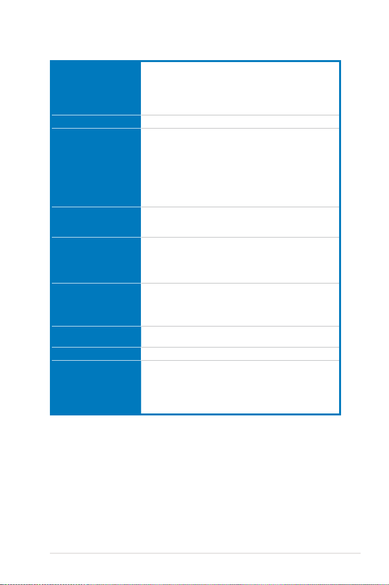
P7H55-M PRO specications summary
CPU
LGA1156 socket for Intel® Core™ i7 / Core™ i5 / Core™ i3 /
Pentium
®
processors
Supports Intel® Turbo Boost Technology*
* The Intel Turbo Boost Technology support depends on the CPU
types.
** Refer to www.asus.com for Intel CPU support list
Chipset
Memory
Intel® H55 Express Chipset
4 x DIMM, max. 16GB, DDR3 2133(O.C.) /1333 / 1066 MHz,
non-ECC, un-buffered memory
Dual channel memory architecture
Supports Intel® Extreme Memory Profile (XMP)
* Hyper DIMM support is subject to the physical characteristics
of individual CPUs. Some hyper DIMMs only support one
DIMM per channel. Please refer to Memory QVL for details.
** Refer to www.asus.com or this user manual for the
Memory QVL (Qualified Vendors Lists)
Expansion Slots
1 x PCI Express 2.0 x16 slot
1 x PCI Express x1 slot
2 x PCI slots
VGA
Multi-VGA output support: HDMI, DVI-D, and RGB ports
Supports HDMI with max. resolution 1920 x 1200 @60Hz
Supports DVI with max. resolution 1920 x 1200 @60Hz
Supports RGB with max. resolution 2048 x 1536 @75Hz
Maximum shared memory of 1748MB
Storage Intel® H55 Express Chipset:
— 6 x SATA 3.0 Gb/s ports
JMicron® JMB368 PATA controller:
— 1 x Ultra DMA 133/100 for up to 2 PATA devices
LAN
USB
Audio
Gigabit LAN controller
®
— Realtek
8112L Gigabit LAN controller featuring AI NET2
12 x USB 2.0 ports (6 ports at mid-board, 6 ports at back panel)
Realtek® 8-channel High Definition Audio CODEC
— BD Audio Layer Content Protection
— Supports Jack-Detection, Multi-streaming and Front Panel
Jack-Retasking (only for Mic In port)
— Optical S/PDIF out port at back I/O
— ASUS Noise Filter
(continued on the next page)
xi

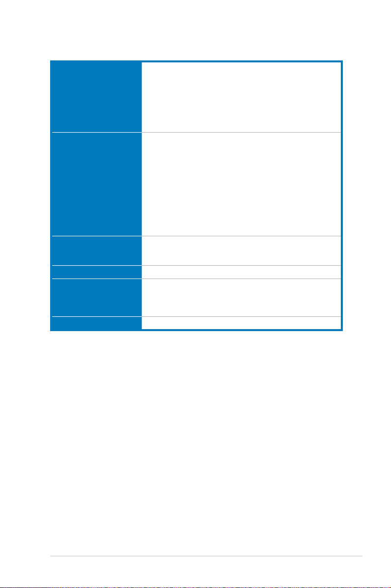
P7H55-M PRO specications summary
ASUS Unique Features ASUS Exclusive Overclocking Features:
ASUS Exclusive
Overclocking Features
— TurboV
— Turbo Key
— GPU Boost
ASUS Power Solutions:
— ASUS EPU
— 4+2 Phase Power Design
ASUS Express Gate
ASUS Quiet Thermal Solution:
— ASUS Fanless Design: Heat-sink solution
— ASUS Fan Xpert
ASUS EZ DIY:
— ASUS Q-DIMM
— ASUS O.C. Profile
— ASUS CrashFree BIOS 3
— ASUS EZ Flash 2
— ASUS My Logo 2
— Multi-language BIOS
Precision Tweaker:
— vCore: Adjustable CPU voltage at 0.00625V increment
— vIMC: Adjustable IMC voltage at 0.05V increment
— vDRAM Bus: Adjustable DRAM voltage at 0.1V increment
— vPCH: Adjustable PCH voltage at 0.05V increment
— vCPU_PLL: Adjustable CPU_PLL voltage at 0.05V increment
SFS (Stepless Frequency Selection):
— Internal Base Clock tuning from 80MHz up to 500 MHz at
1MHz increment
— PCI Express frequency tuning from 100MHz up to 200MHz
at 1MHz increment
Overclocking Protection:
— ASUS C.P.R.(CPU Parameter Recall)
(continued on the next page)
xii
P7H55-M PRO specications summary
Back Panel I/O Ports
Internal I/O Connectors 3 x USB connectors support additional 6 USB ports
BIOS Features
Manageability WfM 2.0, DMI 2.0, WOL by PME, WOR by PME, PXE
Support DVD Contents Drivers
Form Factor
*Specications are subject to change without notice.
1 x PS/2 Keyboard port (purple)
1 x HDMI Output
1 x DVI-D Output
1 x D-Sub Output
1 x Optical S/PDIF Out
1 x RJ45 port
6 x USB 2.0/1.1 ports
8-channel Audio I/O
1 x IDE connector
6 x SATA 3.0Gb/s connectors
1 x CPU Fan connector
1 x 4-pin Chassis Fan connector
1 x Power Fan connector
1 x Front panel audio connector
1 x S/PDIF Out Header
1 x Clear CMOS jumper
1 x 24-pin ATX Power connector
1 x 8-pin EATX 12V Power connector
1 x System Panel
64 Mb Flash ROM, AMI BIOS, PnP, DMI 2.0, WfM 2.0,
SM BIOS 2.5, ACPI 2.0a, Multi-language BIOS,
ASUS EZ Flash 2, ASUS CrashFree BIOS 3
ASUS Utilities
ASUS Update
Anti-virus software (OEM version)
ATX Form Factor, 9.6”x 9.6” (24.4cm x 24.4cm)
xiii

xiv
Chapter 1
Chapter 1: Product introduction
1.1 Welcome!
Thank you for buying an ASUS® P7H55-M PRO motherboard!
The motherboard delivers a host of new features and latest technologies, making it another
standout in the long line of ASUS quality motherboards!
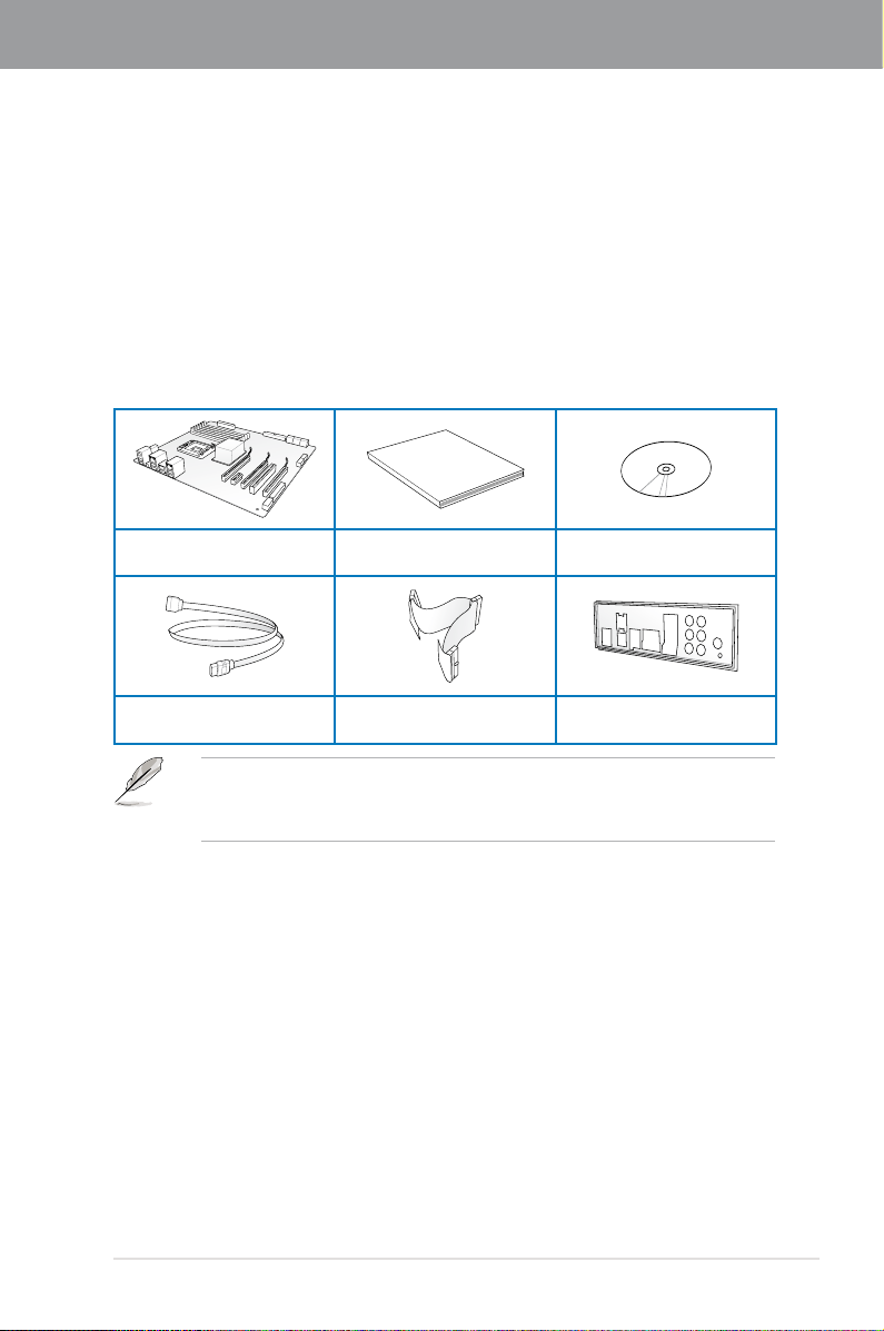
1.2 Package contents
ASUS P7H55-M PRO
motherboard
2 x Serial ATA 3.0Gb/s cables
• If any of the above items is damaged or missing, contact your retailer.
• The illustrated items above are for reference only. Actual product specifications may
vary with different models.
User guide Support DVD
1 x Ultra DMA 133/
100/66 cable
1 x ASUS I/O Shield
ASUS P7H55-M PRO
1-1

1.3 Special features
1.3.1 Product highlights
Chapter 1
Intel® LGA1156 Lynneld / Clarkdale Processor Ready
This motherboard supports the latest Intel® Lynnfield / Clarkdale processors in LGA1156
package, which has memory and PCI Express controller integrated to support 2-channel
(4 DIMMs) DDR3 memory and 16 PCI Express 2.0 lanes, enabling higher graphics
performance. Moreover, Intel® Clarkdale processors integrate Graphics Processing Unit
(GPU), which need to collocate Intel H55 chipset with VGA out by Intel Flexible Display
Interface(FDI) to experience the new generation VGA performance. It provides separated 3D,
2D and Video Engines to execute different graphic control in hardware. Refer to page 2-5 for
details.
Intel® H55
The Intel® H55 Express Chipset is the latest one-chipset design to support the latest 1156
socket Intel® Core™ i7 / Core™ i5 / Core™ i3 / Pentium® processors. Intel H55 provides
improved performance by utilizing serial point-to-point links, allowing increased bandwidth
and stability. Using Intel® Core™ i5 6 Series, Core™ i3 5 Series, and Pentium® CPU with H55
Express Chipset to enjoy the latest Intel integrated graphic performance!
PCIe 2.0
This motherboard supports the latest PCIe 2.0 devices for double speed and bandwidth that
enhances system performance. Refer to page 2-19 for details.
HDMI support
High-Definition Multimedia Interface (HDMI) is a set of digital video standards that delivers
multi-channel audio and uncompressed digital video for full HD 1080p visuals through a
single cable. Supporting HDCP copy protection such as and Blu-ray Discs, HDMI provides
you with the highest-quality home theater experience. Refer to page 2-21 for details.
DVI-D Support
DVI (Digital Visual Interface) provides high visual quality of digital display devices such as
LCD monitor. The interface of this motherboard supports dual display output: DVI-D/HDMI,
VGA/HDMI, or DVI-D/VGA. Refer to page 2-21 for details.
Dual-Channel DDR3 2133(O.C.) / 1333 / 1066 support
The motherboard supports DDR3 memory that features data transfer rates of 2133(O.C.)/
1333 / 1066 MHz to meet the higher bandwidth requirements of the latest 3D graphics,
multimedia, and Internet applications. The dual-channel DDR3 architecture enlarges the
bandwidth of your system memory to boost system performance. Refer to page 2-10 for
details.
Green ASUS
This motherboard and its packaging comply with the European Union’s Restriction on the
use of Hazardous Substances (RoHS). This is in line with the ASUS vision of creating
environment-friendly and recyclable products/packagings to safeguard consumers’ health
while minimizing the impact on the environment.
1-2 Chapter 1: Product Introduction

1.3.2 ASUS Overclocking Features
TurboV
Feel the adrenaline rush of real-time O.C. – now a reality with the ASUS TurboV. This easy
O.C. tool allows you to overclock without exiting or rebooting the OS; and its user-friendly
interface makes overclock with just a few clicks away. Moreover, the ASUS OC profiles in
TurboV provides the best O.C. settings in different scenarios. Refer to page 4-6 for details.
Turbo Key
ASUS Turbo Key allows you to turn the PC power button into a physical overclocking button.
After the easy setup, Turbo Key can boost performances without interrupting ongoing work or
games, simply through pressing the button. Refer to page 4-8 for details.
GPU Boost
GPU Boost overclocks the integrated GPU in real time for the best graphics performance.
User-friendly UI facilitates flexible frequency and voltage adjustments. Its ability to deliver
multiple overclocking profiles also provides rapid and stable system-level upgrades. Refer to
page 4-7 for details.
1.3.3 ASUS Unique Features
Express Gate
Express Gate is an ASUS exclusive OS that provides you with quick access to the Internet
and key applications before entering the Windows® OS. Refer to page 3-37 and 4-10 for
details.
1.3.4 ASUS Power Solutions
4+2 Phase Power Design
Unleashes ultimate memory performances with independent power to core components,
while providing fast transient response and stability for the CPU under heavy loading or
overclocking modes.
ASUS EPU
The new ASUS EPU—the world’s first power saving engine, has been upgraded to a new 6
engine version, which provides total system power savings by detecting current PC loadings
and intelligently moderating power in real-time. With auto phase switching for components
(which includes the CPU, VGA card / integrated GPU, memory, chipset, hard drives and CPU
cooler / system fans), the EPU automatically provides the most appropriate power usage via
intelligent acceleration and overclocking—helping save power and money. Refer to page 4-9
for details.
Chapter 1
ASUS P7H55-M PRO
1-3

Chapter 1
1.3.5 ASUS Quiet Thermal Solutions
ASUS Quiet Thermal solution makes system more stable and enhances the overclocking
capability.
ASUS Fanless Design—Heat-sink solution
The crystal-shaped heatsink features 0-dB thermal solution that offers users a noiseless PC
environment. Not only the beautiful shape upgrades the visual enjoyment for motherboard
users, but also the heatsink design lowers the temperature of the chipset and power phase
area through high efficient heat-exchange. Combined with usability and aesthetics, the ASUS
crystal-shaped heatsink will give users an extremely silent and cooling experience with the
elegant appearance!
Fan Xpert
ASUS Fan Xpert intelligently allows users to adjust both the CPU and chassis fan speed
according to different ambient temperature, which is caused by different climate conditions in
different geographic regions and system loading. Built-in variety of useful profiles offer flexible
controls of fan speed to achieve a quiet and cool environment. Refer to page 4-5 for details.
1.3.6 ASUS Crystal Sound
This feature can enhance speech-centric applications like Skype, online game, video
conference and recording.
8-Channel Audio
The onboard 8-channel HD audio (High Definition Audio, previously codenamed Azalia)
CODEC enables high-quality 192KHz/24-bit audio output, jack-sensing feature, retasking
functions and multi-streaming technology. Refer to page 2-21 for details.
ASUS Noise Filter
This feature detects repetitive and stationary noises like computer fans, air conditioners, and
other background noises then eliminates it in the incoming audio stream while recording.
1.3.7 ASUS EZ DIY
ASUS EZ DIY feature collection provides you easy ways to install computer components,
update the BIOS or back up your favorite settings.
ASUS EZ-Flash 2
Simply update BIOS from a USB ash drive before entering the OS
EZ Flash 2 is a user-friendly BIOS update utility. Simply launch this tool and update BIOS
from a USB flash drive before entering the OS. You can update your BIOS only in a few clicks
without preparing an additional floppy diskette or using an OS-based flash utility. Refer to
page 3-4 for details.
1-4 Chapter 1: Product Introduction

ASUS CrashFree BIOS 3
The ASUS CrashFree BIOS 3 allows users to restore corrupted BIOS data from a USB flash
disk containing the BIOS file. Refer to page 3-5 for details.
ASUS O.C. Prole
Freely share and distribute favorite overclocking settings. The motherboard features the
ASUS O.C. Profile that allows users to conveniently store or load multiple BIOS settings. The
BIOS settings can be stored in the CMOS or a separate file, giving users freedom to share
and distribute their favorite overclocking settings. Refer to page 3-35 for details.
ASUS Q-DIMM
ASUS Q-DIMM enhances your DIY experience by speeding up and simplifying the DIY
process!
Chapter 1
ASUS P7H55-M PRO
1-5

Chapter 1
1-6 Chapter 1: Product Introduction
Chapter 2
Chapter 2: Hardware information
2.1 Before you proceed
Take note of the following precautions before you install motherboard components or change
any motherboard settings.
• Unplug the power cord from the wall socket before touching any component.
• Before handling components, use a grounded wrist strap or touch a safely grounded
object or a metal object, such as the power supply case, to avoid damaging them due
to static electricity.
• Hold components by the edges to avoid touching the ICs on them.
• Whenever you uninstall any component, place it on a grounded antistatic pad or in the
bag that came with the component.
• Before you install or remove any component, ensure that the ATX power supply is
switched off or the power cord is detached from the power supply. Failure to do so
may cause severe damage to the motherboard, peripherals, or components.
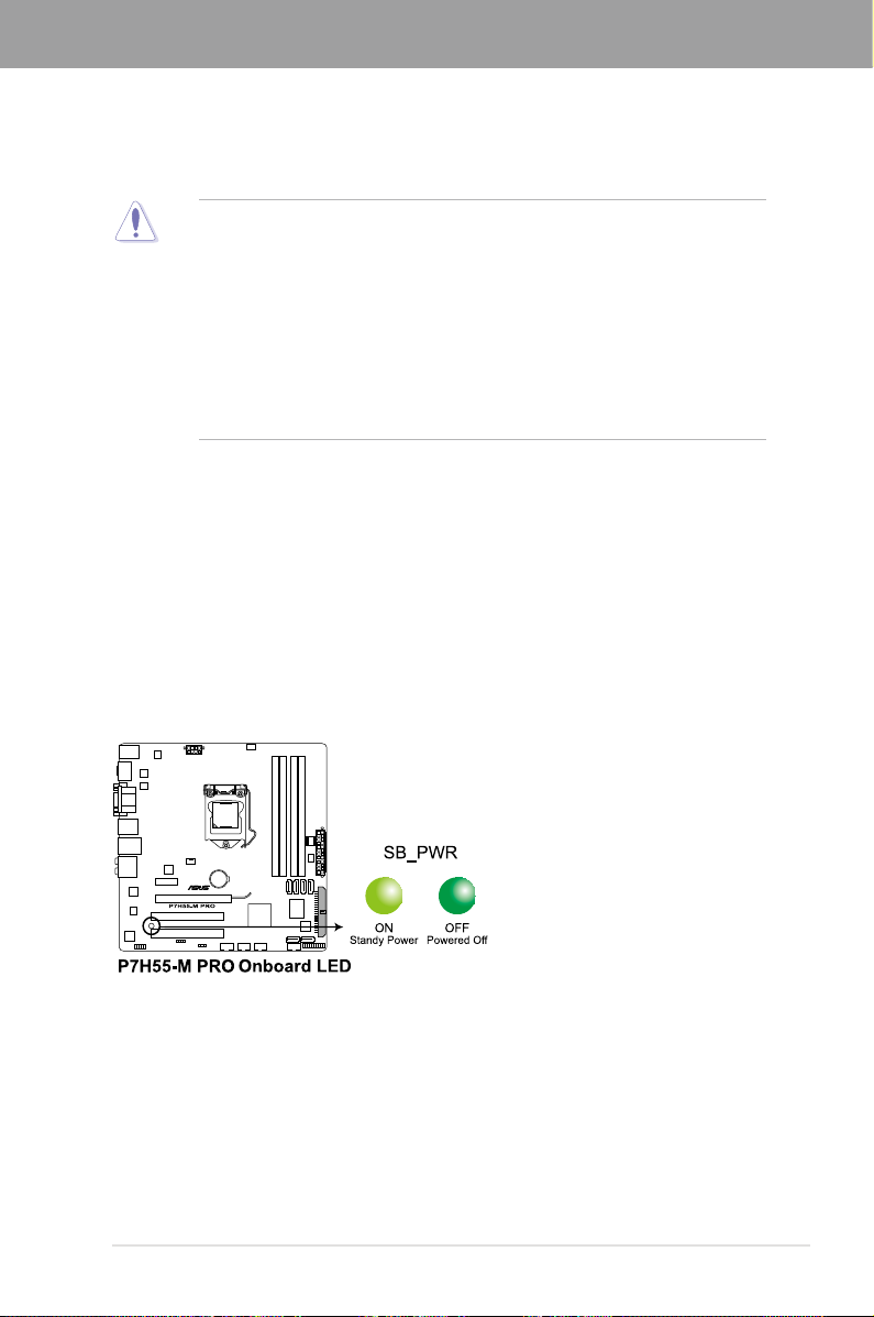
Onboard LED
The motherboard comes with a standby power LED that lights up to indicate that the system
is ON, in sleep mode, or in soft-off mode. This is a reminder that you should shut down
the system and unplug the power cable before removing or plugging in any motherboard
component. The illustration below shows the location of the onboard LED.
ASUS P7H55-M PRO 2-1
Chapter 2
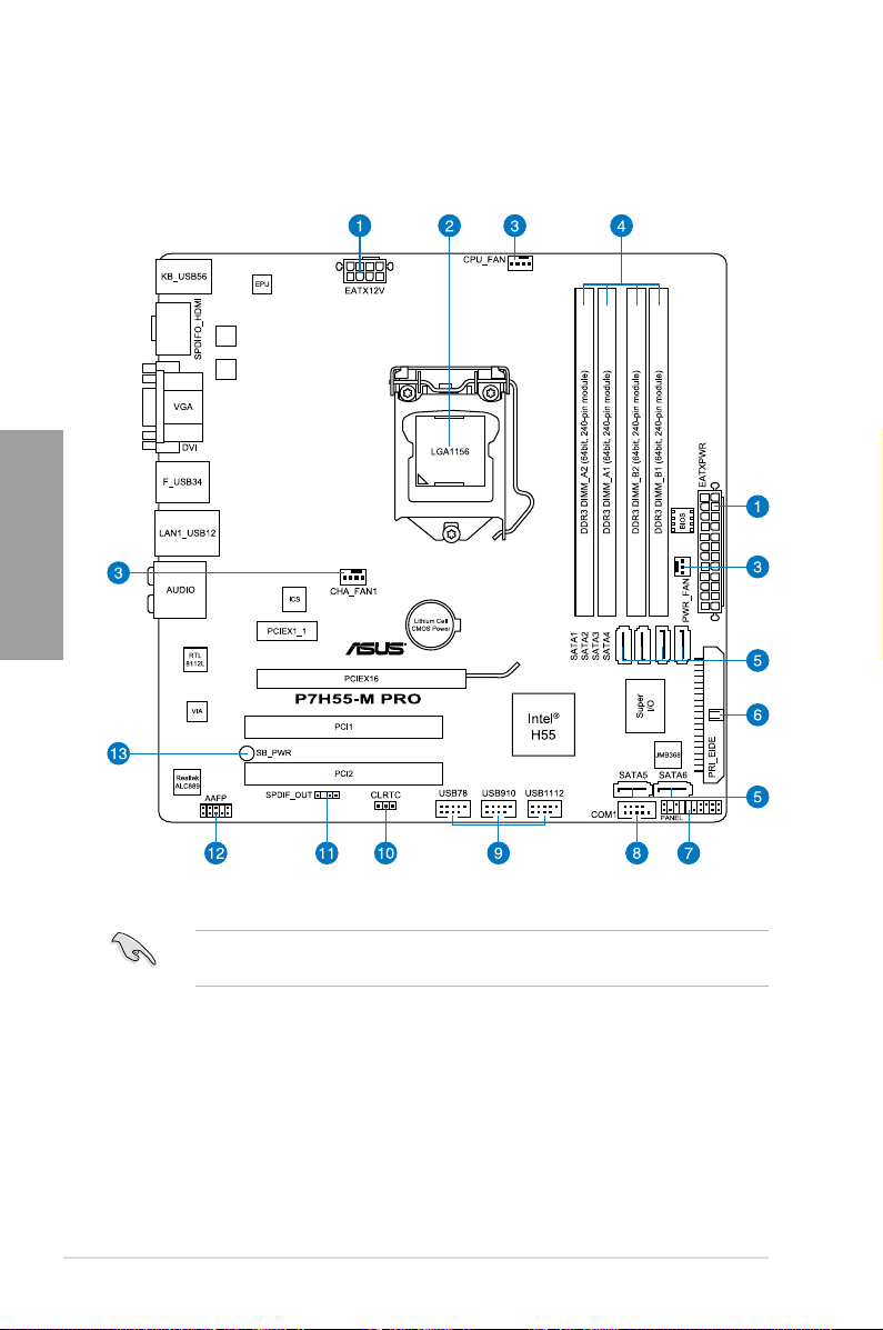
2.2 Motherboard overview
2.2.1 Motherboard layout
2.7 Connectors
Refer to
connectors.
2-2 Chapter 2: Hardware information
for more information about rear panel connectors and internal
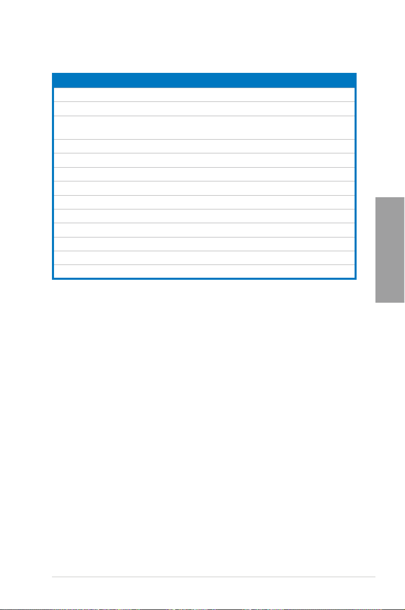
2.2.2 Layout contents
Connectors/Jumpers/Slots Page
1. ATX power connectors (24-pin EATXPWR, 8-pin EATX12V) 2-31
2. LGA1156 CPU Socket
3. CPU, chassis, and power fan connectors (4-pin CPU_FAN,
4-pin CHA_FAN1, 3-pin PWR_FAN)
4. DDR3 DIMM slots
5. Intel
6. IDE connector (40-1 pin PRI_EIDE)
7. System panel connector (20-8 pin PANEL)
8. Serial port connector (10-1 pin COM1)
9. USB connectors (10-1 pin USB78, USB910, USB1112)
10. Clear RTC RAM (3-pin CLRTC)
11. Digital audio connector (4-1 pin SPDIF_OUT)
12. Front panel audio connector (10-1 pin AAFP)
13. Standby power LED
®
H55 Serial ATA connectors (7-pin SATA 1-6) 2-27
2-5
2-29
2-10
2-26
2-32
2-28
2-28
2-45
2-30
2-30
2-1
Chapter 2
ASUS P7H55-M PRO 2-3
Chapter 2
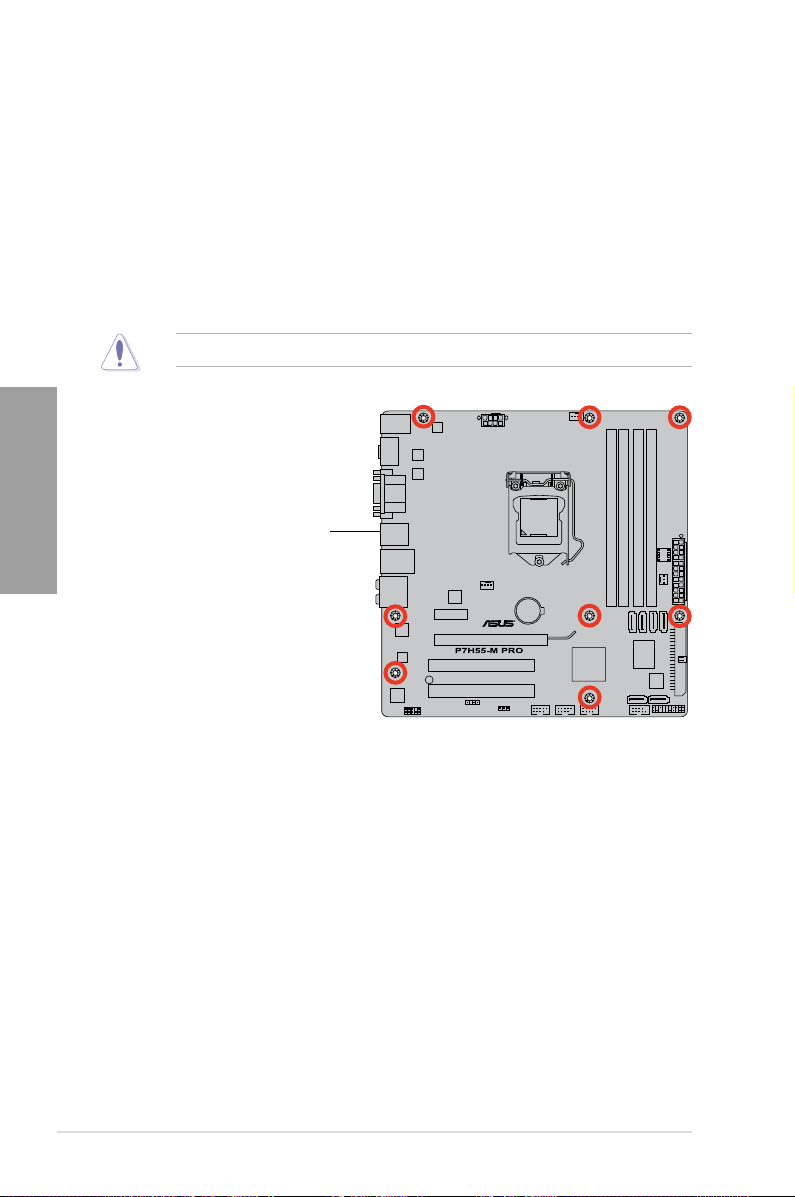
2.2.3 Placement direction
When installing the motherboard, ensure that you place it into the chassis in the correct
orientation. The edge with external ports goes to the rear part of the chassis as indicated in
the image below.
2.2.4 Screw holes
Place eight screws into the holes indicated by circles to secure the motherboard to the
chassis.
DO NOT overtighten the screws! Doing so can damage the motherboard.
Place this side towards
the rear of the chassis
2-4 Chapter 2: Hardware information
2.3 Central Processing Unit (CPU)
The motherboard comes with a surface mount LGA1156 socket designed for the Intel®
Core™ i7 / Core™ i5 / Core™ i3 / Pentium® processors.
Ensure that all power cables are unplugged before installing the CPU.
• Upon purchase of the motherboard, ensure that the PnP cap is on the socket and
the socket contacts are not bent. Contact your retailer immediately if the PnP cap
is missing, or if you see any damage to the PnP cap/socket contacts/motherboard
components. ASUS will shoulder the cost of repair only if the damage is shipment/
transit-related.
• Keep the cap after installing the motherboard. ASUS will process Return Merchandise
Authorization (RMA) requests only if the motherboard comes with the cap on the
LGA1156 socket.
• The product warranty does not cover damage to the socket contacts resulting from
incorrect CPU installation/removal, or misplacement/loss/incorrect removal of the PnP
cap.
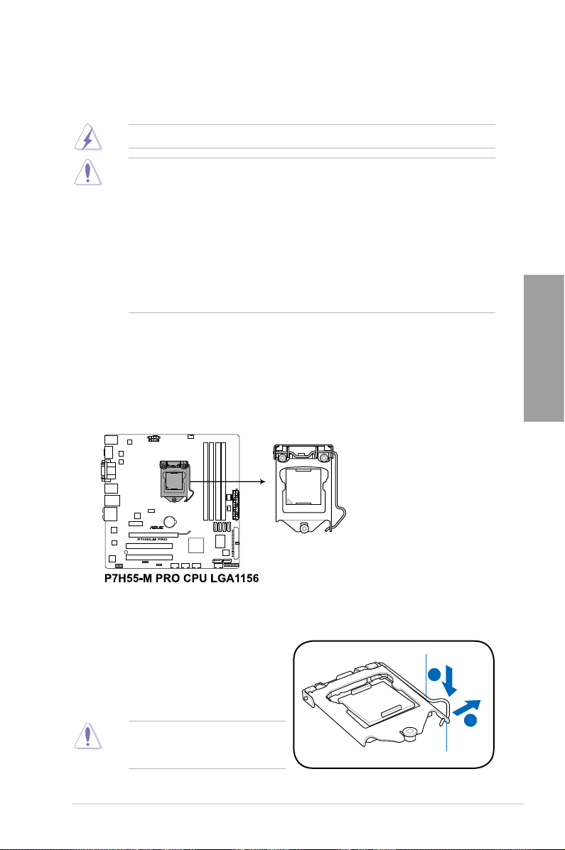
2.3.1 Installing the CPU
To install a CPU:
1. Locate the CPU socket on the motherboard.
Chapter 2
2. Press the load lever with your thumb (A),
and then move it to the right (B) until it is
Load lever
released from the retention tab.
To prevent damage to the socket pins,
do not remove the PnP cap unless
you are installing a CPU.
Retention tab
ASUS P7H55-M PRO 2-5
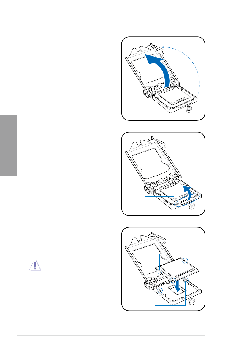
Chapter 2
3. Lift the load lever in the direction of the
arrow until the load plate is completely
lifted.
Load plate
4. Remove the PnP cap from the CPU
socket by lifting the tab only.
PnP cap
Cap tab
5. Position the CPU over the socket,
ensuring that the gold triangle is on the
bottom-left corner of the socket, and then
fit the socket alignment keys into the CPU
CPU notches
notches.
The CPU fits in only one correct
orientation. DO NOT force the CPU
into the socket to prevent bending
the connectors on the socket and
damaging the CPU!
2-6 Chapter 2: Hardware information
Gold
triangle
mark
Alignment keys
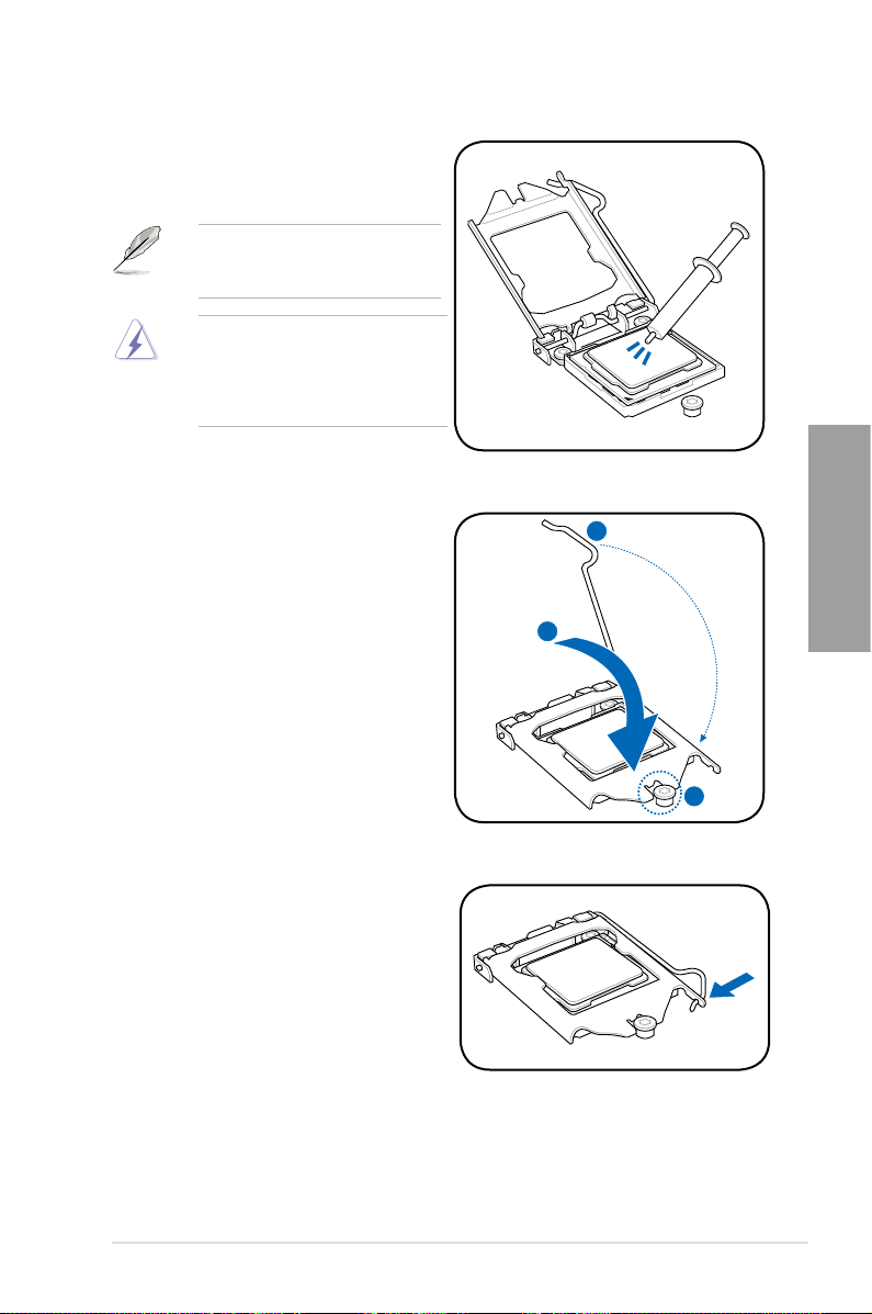
6. Apply some Thermal Interface Material
to the exposed area of the CPU that the
heatsink will be in contact with, ensuring
that it is spread in an even thin layer.
Some heatsinks come with preapplied thermal paste. If so, skip this
step.
The Thermal Interface Material is
toxic and inedible. DO NOT eat it. If
it gets into your eyes or touches your
skin, wash it off immediately, and seek
professional medical help.
7. Close the load plate (A), and then push
down the load lever (B), ensuring that
the front edge of the load plate slides
under the retention lock (C).
Chapter 2
8. Insert the load lever under the retention
tab.
ASUS P7H55-M PRO 2-7
Chapter 2
2.3.2 Installing the CPU heatsink and fan
The Intel® LGA1156 processor requires a specially designed heatsink and fan assembly to
ensure optimum thermal condition and performance.
• When you buy a boxed Intel® processor, the package includes the CPU fan and
heatsink assembly. If you buy a CPU separately, ensure that you use only
Intel®-certified multi-directional heatsink and fan.
®
• Your Intel
• Use an LGA1156-compatible CPU heatsink and fan assembly only. The LGA1156
If you purchased a separate CPU heatsink and fan assembly, ensure that the Thermal
Interface Material is properly applied to the CPU heatsink or CPU before you install the
heatsink and fan assembly.
Ensure that you have installed the motherboard to the chassis before you install the CPU
fan and heatsink assembly.
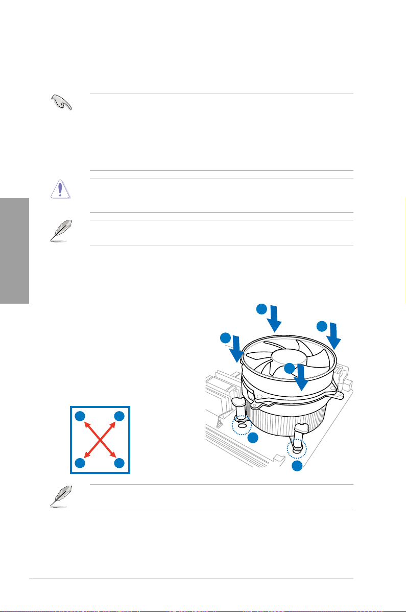
To install the CPU heatsink and fan:
LGA1156 heatsink and fan assembly comes in a push-pin design and
requires no tool to install.
socket is incompatible with the LGA775 and LGA1366 sockets in size and dimension.
1. Place the heatsink on top of the installed
A
CPU, ensuring that the four fasteners
match the holes on the motherboard.
2. Push down two fasteners at a time in
B
B
a diagonal sequence to secure the
heatsink and fan assembly in place.
A
B
A
1
B
2-8 Chapter 2: Hardware information
A
Orient the heatsink and fan assembly such that the CPU fan cable is closest to the CPU fan
connector.
1
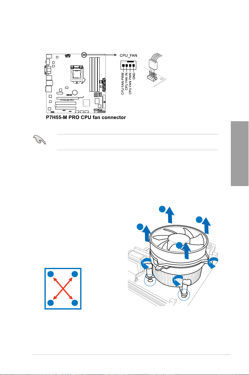
3. Connect the CPU fan cable to the connector on the motherboard labeled CPU_FAN.
DO NOT forget to connect the CPU fan connector! Hardware monitoring errors can occur if
you fail to plug this connector.
2.3.3 Uninstalling the CPU heatsink and fan
To uninstall the CPU heatsink and fan:
Chapter 2
1. Disconnect the CPU fan cable from the
connector on the motherboard.
2. Rotate each fastener counterclockwise.
3. Pull up two fasteners at a time in a
B
A
B
diagonal sequence to disengage the
heatsink and fan assembly from the
motherboard.
A
B
B
A
A
4. Carefully remove the heatsink and fan assembly from the motherboard.
ASUS P7H55-M PRO 2-9
Chapter 2
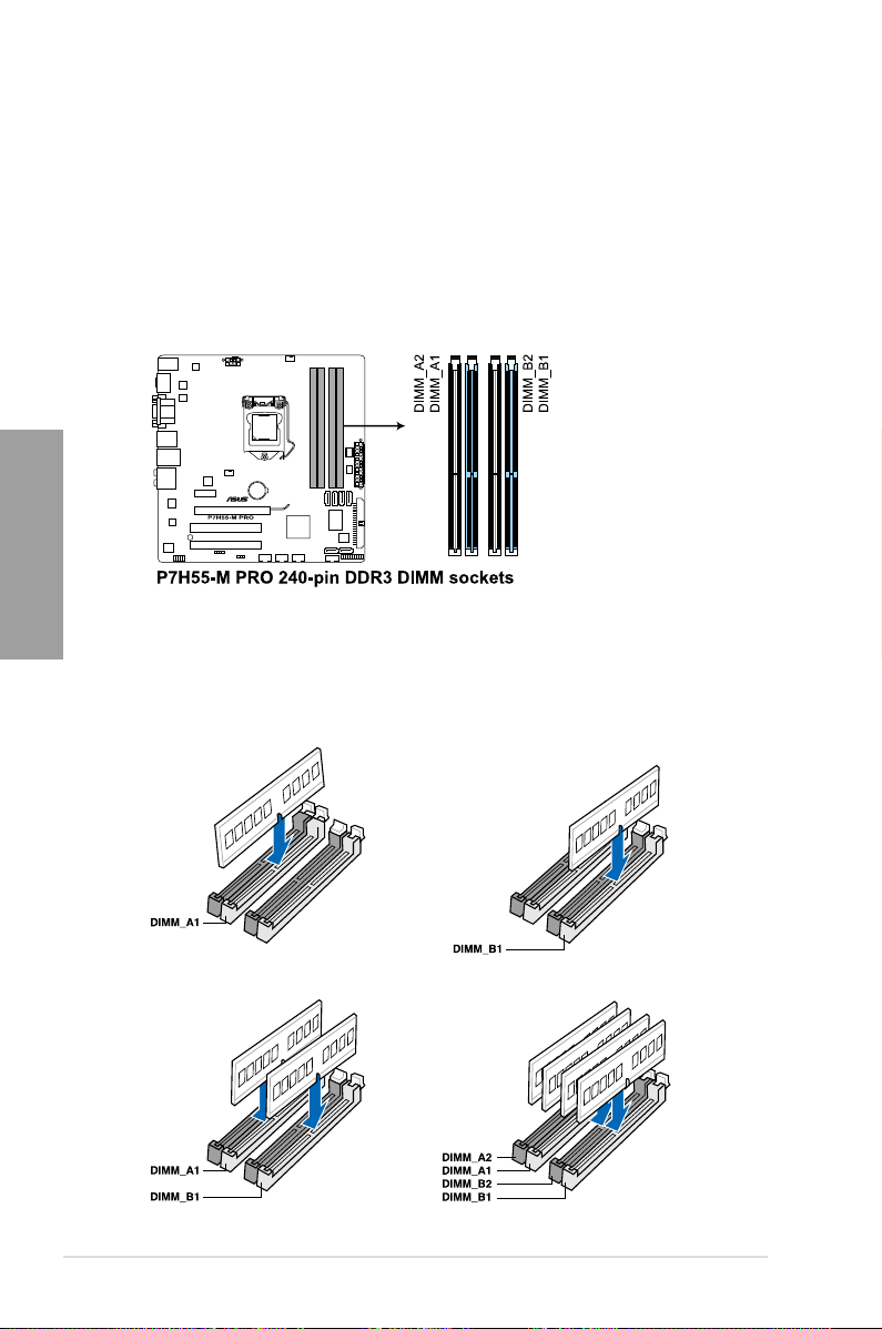
2.4 System memory
2.4.1 Overview
The motherboard comes with four Double Data Rate 3 (DDR3) Dual In-line Memory Modules
(DIMM) sockets.
A DDR3 module has the same physical dimensions as a DDR2 DIMM but is notched
differently to prevent installation on a DDR2 DIMM socket. DDR3 modules are developed for
better performance with less power consumption.
The figure illustrates the location of the DDR3 DIMM sockets:
Recommended memory congurations
One DIMM:
Install only one memory module in slot A1 or B1 as a single-channel operation.
Four DIMMs (dual-channel operation):Two DIMMs (dual-channel operation):
2-10 Chapter 2: Hardware information
Loading…
Предлагаем вам документ Руководство по эксплуатации на ASUS P7H55DM_PRO: PDF файл 5.99 Mb, 110 страниц.
Руководство по эксплуатации P7H55DM_PRO — читать онлайн или скачать бесплатно. Также, вы можете задать любой вопрос про ASUS P7H55DM_PRO.
BB код
Прямой урл
Скачать файл Руководство по эксплуатации ASUS P7H55DM_PRO
Размер файла: 5.99 Mb
Кол-во страниц: 110
Просмотров: 3082
Тип файла: Portable Document Format (PDF)
Вы робот?
60
Скачать Руководство по эксплуатации:
asus-p7h55dm-pro-owner-s-manual.pdf

Читать онлайн ASUS P7H55DM_PRO Руководство по эксплуатации
←
1/110
→
←
1/110
→
Manuals.eu
- Manuals.eu
- ASUS
- Computers & Peripherals
- Motherboards
- LGA1156
- P7H55D-M PRO
- User’s manual (English)
×
1
2
3
4
5
6
7
8
9
10
11
12
13
14
15
16
17
18
19
20
21
22
23
24
25
26
27
28
29
30
31
32
33
34
35
36
37
38
39
40
41
42
43
44
45
46
47
48
49
50
51
52
53
54
55
56
57
58
59
60
61
62
63
64
65
66
67
68
69
70
71
72
73
74
75
76
77
78
79
80
81
82
83
84
85
86
87
88
89
90
91
92
93
94
95
96
97
98
99
100
101
102
103
104
⟨
⟩
Copyright © Manuals.eu
Agreement
Privacy Policy
Contact us