

MAXIMUS VI
EXTREME
Motherboard

E7948
First Edition
April 2013
Copyright © 2013 ASUSTeK COMPUTER INC. All Rights Reserved.
No part of this manual, including the products and software described in it, may be reproduced,
transmitted, transcribed, stored in a retrieval system, or translated into any language in any form or by any
means, except documentation kept by the purchaser for backup purposes, without the express written
permission of ASUSTeK COMPUTER INC. (“ASUS”).
Product warranty or service will not be extended if: (1) the product is repaired, modied or altered, unless
such repair, modication of alteration is authorized in writing by ASUS; or (2) the serial number of the
product is defaced or missing.
ASUS PROVIDES THIS MANUAL “AS IS” WITHOUT WARRANTY OF ANY KIND, EITHER EXPRESS
OR IMPLIED, INCLUDING BUT NOT LIMITED TO THE IMPLIED WARRANTIES OR CONDITIONS OF
MERCHANTABILITY OR FITNESS FOR A PARTICULAR PURPOSE. IN NO EVENT SHALL ASUS, ITS
DIRECTORS, OFFICERS, EMPLOYEES OR AGENTS BE LIABLE FOR ANY INDIRECT, SPECIAL,
INCIDENTAL, OR CONSEQUENTIAL DAMAGES (INCLUDING DAMAGES FOR LOSS OF PROFITS,
LOSS OF BUSINESS, LOSS OF USE OR DATA, INTERRUPTION OF BUSINESS AND THE LIKE),
EVEN IF ASUS HAS BEEN ADVISED OF THE POSSIBILITY OF SUCH DAMAGES ARISING FROM ANY
DEFECT OR ERROR IN THIS MANUAL OR PRODUCT.
SPECIFICATIONS AND INFORMATION CONTAINED IN THIS MANUAL ARE FURNISHED FOR
INFORMATIONAL USE ONLY, AND ARE SUBJECT TO CHANGE AT ANY TIME WITHOUT NOTICE,
AND SHOULD NOT BE CONSTRUED AS A COMMITMENT BY ASUS. ASUS ASSUMES NO
RESPONSIBILITY OR LIABILITY FOR ANY ERRORS OR INACCURACIES THAT MAY APPEAR IN THIS
MANUAL, INCLUDING THE PRODUCTS AND SOFTWARE DESCRIBED IN IT.
Products and corporate names appearing in this manual may or may not be registered trademarks or
copyrights of their respective companies, and are used only for identication or explanation and to the
owners’ benet, without intent to infringe.
Offer to Provide Source Code of Certain Software
This product contains copyrighted software that is licensed under the General Public License (“GPL”),
under the Lesser General Public License Version (“LGPL”) and/or other Free Open Source Software
Licenses. Such software in this product is distributed without any warranty to the extent permitted by the
applicable law. Copies of these licenses are included in this product.
Where the applicable license entitles you to the source code of such software and/or other additional data,
you may obtain it for a period of three years after our last shipment of the product, either
(1) for free by downloading it from http://support.asus.com/download
or
(2) for the cost of reproduction and shipment, which is dependent on the preferred carrier and the location
where you want to have it shipped to, by sending a request to:
ASUSTeK Computer Inc.
Legal Compliance Dept.
15 Li Te Rd.,
Beitou, Taipei 112
Taiwan
In your request please provide the name, model number and version, as stated in the About Box of the
product for which you wish to obtain the corresponding source code and your contact details so that we
can coordinate the terms and cost of shipment with you.
The source code will be distributed WITHOUT ANY WARRANTY and licensed under the same license as
the corresponding binary/object code.
This offer is valid to anyone in receipt of this information.
ASUSTeK is eager to duly provide complete source code as required under various Free Open Source
Software licenses. If however you encounter any problems in obtaining the full corresponding source
code we would be much obliged if you give us a notication to the email address gpl@asus.com, stating
the product and describing the problem (please DO NOT send large attachments such as source code
archives, etc. to this email address).
ii

Contents
Safety information ……………………………………………………………………………………….. vii
About this guide …………………………………………………………………………………………. viii
MAXIMUS VI EXTREME specications summary ……………………………………………. x
OC Panel specications summary ………………………………………………………………..xv
Package contents ……………………………………………………………………………………….. xvi
Installation tools and components ……………………………………………………………… xvii
Chapter 1: Product Introduction
1.1 Special features………………………………………………………………………………1-1
1.1.1 Product highlights
1.1.2 ROG Intelligent Performance & Overclocking features ……………
1.1.3 ASUS special features ……………………………………………………….
1.1.4 ROG-rich bundled software
1.2 Motherboard overview …………………………………………………………………….
1.2.1 Before you proceed ……………………………………………………………
1.2.2 Motherboard layout ……………………………………………………………
1.2.3 Central Processing Unit (CPU) ……………………………………………
1.2.4 System memory ………………………………………………………………
1.2.5 Expansion slots ……………………………………………………………….
1.2.6 Onboard buttons and switches
1.2.7 Jumpers …………………………………………………………………………
1.2.8 Onboard LEDs ………………………………………………………………..
1.2.9 Internal connectors
1.2.10 ProbeIt
…………………………………………………………………………… 1-48
……………………………………………………………… 1-1
………………………………………………… 1-4
………………………………………….. 1-22
………………………………………………………….. 1-37
1-2
1-4
1-6
1-6
1-7
1-9
1-10
1-19
1-27
1-28
Chapter 2: Basic Installation
2.1 Building your PC system…………………………………………………………………2-1
2.1.1 Motherboard installation ……………………………………………………..
2.1.2 CPU installation
2.1.3 CPU heatsink and fan assembly installation ………………………….
2.1.4 DIMM installation
2.1.5 ATX Power connection ……………………………………………………….
2.1.6 SATA device connection ……………………………………………………..
2.1.7 Front I/O Connector …………………………………………………………..
2.1.8 Expansion Card installation
2.1.9 mPCIe Combo II installation
………………………………………………………………… 2-3
………………………………………………………………. 2-6
………………………………………………. 2-10
……………………………………………… 2-11
2-1
2-4
2-7
2-8
2-9
iii

2.2 BIOS update utility ……………………………………………………………………….. 2-15
2.3 Motherboard rear and audio connections ………………………………………
2.3.1 Rear I/O connection …………………………………………………………
2.3.2 Audio I/O connections ………………………………………………………
2.4 OC Panel ………………………………………………………………………………………
2.4.1 OC Panel Overview
2.4.2 Setting up your OC Panel in Normal Mode ………………………….
2.4.3 Setting up your OC Panel in Extreme Mode ………………………..
2.5 Starting up for the rst time …………………………………………………………..
2.6 Turning off the computer ……………………………………………………………….
…………………………………………………………. 2-21
2-16
2-16
2-17
2-21
2-23
2-25
2-26
2-26
Chapter 3: BIOS setup
3.1 Knowing BIOS ………………………………………………………………………………..3-1
3.2 BIOS setup program ……………………………………………………………………….
3.2.1 EZ Mode
3.2.2 Advanced Mode ………………………………………………………………..
3.3 My Favorites …………………………………………………………………………………..
3.4 Extreme Tweaker menu …………………………………………………………………..
3.5 Main menu ……………………………………………………………………………………
3.6 Advanced menu ……………………………………………………………………………
3.6.1 CPU Conguration …………………………………………………………..
3.6.2 PCH Conguration …………………………………………………………..
3.6.3 SATA Conguration ………………………………………………………….
3.6.4 System Agent Conguration
3.6.5 USB Conguration …………………………………………………………..
3.6.6 Platform Misc Conguration ………………………………………………
3.6.7 Onboard Devices Conguration …………………………………………
3.6.8 APM ………………………………………………………………………………
3.6.9 Network Stack …………………………………………………………………
3.5.10 LED Control
3.7 Monitor menu ……………………………………………………………………………….
3.8 Boot menu ……………………………………………………………………………………
3.9 Tools menu …………………………………………………………………………………..
3.9.1 ASUS EZ Flash 2 Utility ……………………………………………………
3.9.2 ASUS O.C. Prole ……………………………………………………………
3.9.3 ASUS SPD Information …………………………………………………….
3.9.4 BIOS Flashback ………………………………………………………………
3.10 Exit menu ……………………………………………………………………………………..
………………………………………………………………………….. 3-3
……………………………………………… 3-32
……………………………………………………………………. 3-39
3-2
3-4
3-6
3-7
3-22
3-25
3-26
3-29
3-31
3-34
3-35
3-36
3-38
3-39
3-40
3-44
3-48
3-48
3-48
3-49
3-50
3-51
iv

3.11 Updating BIOS ……………………………………………………………………………… 3-52
3.11.1 ASUS EZ Flash 2 …………………………………………………………….
3.11.2 ASUS CrashFree BIOS 3 ………………………………………………….
3.11.3 ASUS BIOS Updater ………………………………………………………..
3.12 Secure Erase ………………………………………………………………………………..
3-53
3-54
3-55
3-58
Chapter 4: Software support
4.1 Installing an operating system ………………………………………………………..4-1
4.2 Support DVD information ………………………………………………………………..
4.2.1 Running the support DVD …………………………………………………..
4.2.2 Obtaining the software manuals
………………………………………….. 4-3
4.3 Software information ………………………………………………………………………
4.4 AI Suite 3 ………………………………………………………………………………………..
4.4.1 Dual Intelligent Processors 4 ………………………………………………
4.4.2 Wi-Fi GO! ……………………………………………………………………….
4.4.3 Wi-Fi Engine
…………………………………………………………………… 4-22
4.4.4 EZ Update ………………………………………………………………………
4.4.5 USB 3.0 Boost
………………………………………………………………… 4-25
4.4.6 System Information ………………………………………………………….
4.4.7 USB BIOS Flashback Wizard
……………………………………………. 4-28
4.4.8 Ai Charger+ …………………………………………………………………….
4.4.9 USB Charger+ …………………………………………………………………
4.4.10 Audio congurations
4.4.11 ROG Connect
………………………………………………………… 4-31
…………………………………………………………………. 4-32
4.4.12 MemTweakIt ……………………………………………………………………
4.4.13 RAMDisk ………………………………………………………………………..
4-1
4-1
4-4
4-4
4-7
4-14
4-24
4-26
4-29
4-30
4-34
4-37
Chapter 5: RAID support
5.1 RAID congurations ……………………………………………………………………….5-1
5.1.1 RAID denitions ………………………………………………………………..
5.1.2 Installing Serial ATA hard disks ……………………………………………
5.1.3 Setting the RAID item in BIOS …………………………………………….
5.1.4 Intel
5.2 Creating a RAID driver disk
®
Rapid Storage Technology Option ROM utility ………………5-3
…………………………………………………………….. 5-8
5.2.1 Creating a RAID driver disk without entering the OS ………………
5.2.2 Creating a RAID driver disk in Windows
5.2.3 Installing the RAID driver during Windows
®
………………………………5-8
®
OS installation …….. 5-9
5-1
5-2
5-2
5-8
v

Appendices
Notices …………………………………………………………………………………………………….. A-1
ASUS contact information ………………………………………………………………………….. A-5
vi

Safety information
Electrical safety
To prevent electrical shock hazard, disconnect the power cable from the electrical outlet
•
before relocating the system.
When adding or removing devices to or from the system, ensure that the power cables
•
for the devices are unplugged before the signal cables are connected. If possible,
disconnect all power cables from the existing system before you add a device.
Before connecting or removing signal cables from the motherboard, ensure that all
•
power cables are unplugged.
Seek professional assistance before using an adapter or extension cord. These devices
•
could interrupt the grounding circuit.
Ensure that your power supply is set to the correct voltage in your area. If you are not
•
sure about the voltage of the electrical outlet you are using, contact your local power
company.
If the power supply is broken, do not try to x it by yourself. Contact a qualied service
•
technician or your retailer.
Operation safety
Before installing the motherboard and adding devices on it, carefully read all the manuals
•
that came with the package.
Before using the product, ensure all cables are correctly connected and the power
•
cables are not damaged. If you detect any damage, contact your dealer immediately.
To avoid short circuits, keep paper clips, screws, and staples away from connectors,
•
slots, sockets and circuitry.
Avoid dust, humidity, and temperature extremes. Do not place the product in any area
•
where it may become wet.
Place the product on a stable surface.
•
If you encounter technical problems with the product, contact a qualied service
•
technician or your retailer.
vii

About this guide
This user guide contains the information you need when installing and conguring the
motherboard.
How this guide is organized
This guide contains the following parts:
• Chapter 1: Product introduction
This chapter describes the features of the motherboard and the new technology it
supports. It includes description of the switches, jumpers, and connectors on the
motherboard.
• Chapter 2: Basic Installation
This chapter lists the hardware setup procedures that you have to perform when
installing system components.
• Chapter 3: BIOS setup
This chapter tells how to change system settings through the BIOS Setup menus.
Detailed descriptions of the BIOS parameters are also provided.
• Chapter 4: Software support
This chapter describes the contents of the support DVD that comes with the
motherboard package and the software.
• Chapter 5: RAID support
This chapter describes the RAID congurations.
Where to nd more information
Refer to the following sources for additional information and for product and software
updates.
1. ASUS websites
The ASUS website provides updated information on ASUS hardware and software
products. Refer to the ASUS contact information.
2. Optional documentation
Your product package may include optional documentation, such as warranty yers,
that may have been added by your dealer. These documents are not part of the
standard package.
viii

Conventions used in this guide
To ensure that you perform certain tasks properly, take note of the following symbols used
throughout this manual.
DANGER/WARNING: Information to prevent injury to yourself when trying to
complete a task.
CAUTION: Information to prevent damage to the components when trying to
complete a task
IMPORTANT: Instructions that you MUST follow to complete a task. .
NOTE: Tips and additional information to help you complete a task.
Typography
Bold text Indicates a menu or an item to select.
Italics
<Key> Keys enclosed in the less-than and greater-than sign
<Key1> + <Key2> + <Key3> If you must press two or more keys simultaneously, the key
Used to emphasize a word or a phrase.
means that you must press the enclosed key.
Example: <Enter> means that you must press the Enter or
Return key.
names are linked with a plus sign (+).
ix

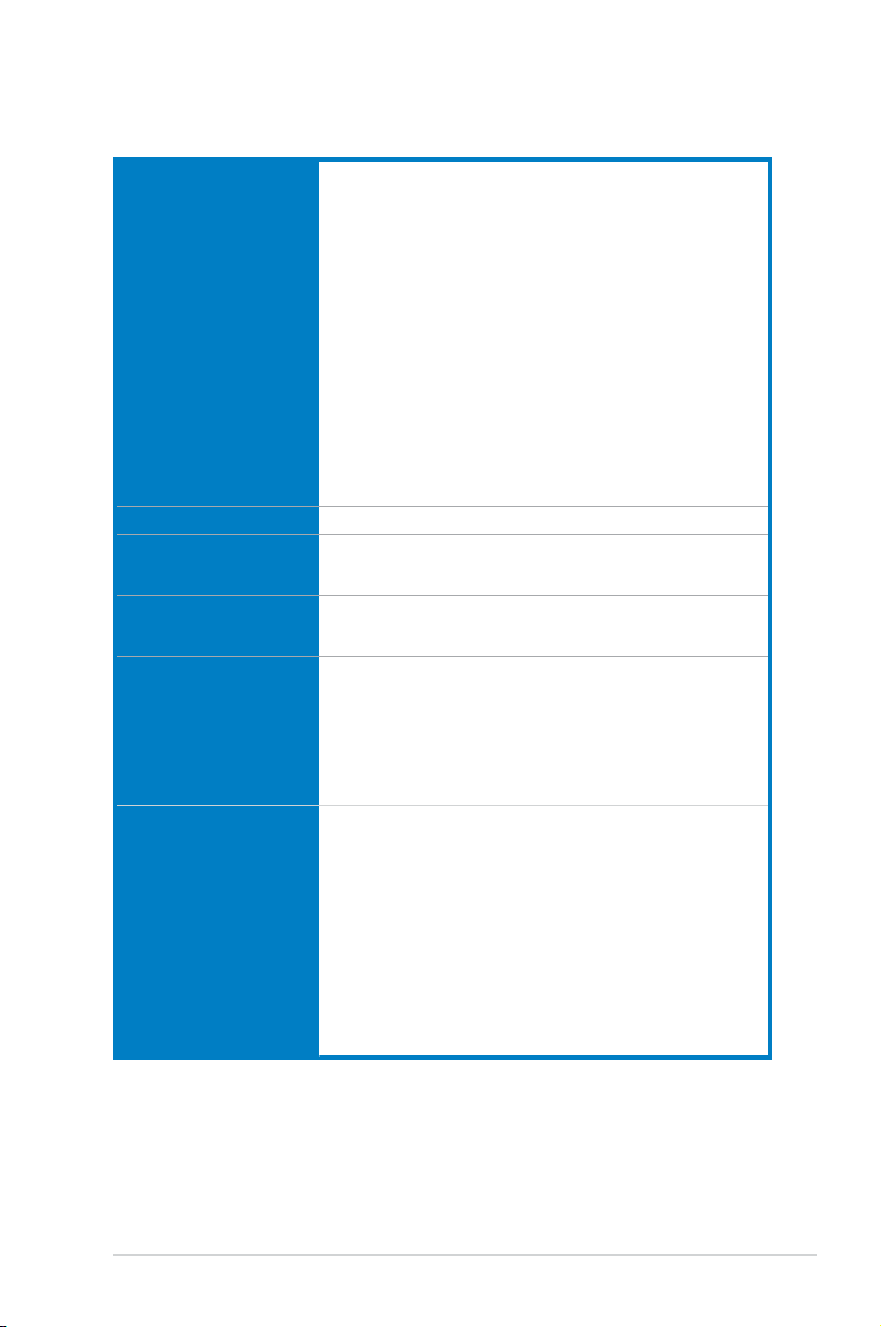
MAXIMUS VI EXTREME specications summary
CPU
Chipset
Memory
Expansion slots
VGA
Multi-GPU support
LGA1150 socket for 4th Generation Intel® Core™ i7 /
Intel® Core™ i5 / Intel
®
Core™ i3, Pentium®, Celeron® Processors
Supports 22nm CPU
Supports Intel® Turbo Boost Technology 2.0*
* The Intel® Turbo Boost Technology 2.0 support depends on the CPU
type.
** Refer to www.support.asus.com/cpu.aspx for Intel CPU support list.
Intel® Z87 Express Chipset
Dual channel memory architecture
4 x DIMM, max. 32GB, DDR3 2800(O.C.) / 2666(O.C.) /
2600(O.C.) / 2500 (O.C.) / 2400 (O.C.) / 2200(O.C.) /
2133(O.C.) / 2000(O.C.) / 1866(O.C.) / 1800(O.C.) / 1600 / 1333
MHz, non-ECC, un-buffered memory
Supports Intel® Extreme Memory Prole (XMP)
* Hyper DIMM support is subject to the physical characteristics of
individual CPUs.
** Please refer to Memory QVL (Qualied Vendors List) for details.
5 x PCI Express 3.0*/2.0 x16 slots (single at native x16, dual at
x8/x8**, triple at x8/x16/x8, quad at x8/x16/x8/x8)
1 x PCI Express 2.0 x4 slot
1 x mini-PCI Express 2.0 x1 slot*** on mPCIe Combo II expansion
card
* PCIe 3.0 speed is supported by 4th generation Intel® Core™ Processors.
** Native x8/x8 mode is available only when PCIE_x16/x8_1 and
PCIE_x8_B2 slots are in use.
*** The mini-PCIe slot is pre-installed with a Wi-Fi/Bluetooth module.
Integrated Intel® HD Graphics Processor
Multi-VGA output support: DisplayPort/HDMI port
DisplayPort 1.2 with max. resolution of 4096 x 2160 @ 24 Hz/
3840 x 2160 at 60Hz
HDMI with max. resolution of 4096 x 2160 at 24Hz / 2560 x 1600
at 60Hz
Intel® InTru™ 3D/ Intel® Quick Sync Video/ Intel® Clear Video HD
Technology/ Intel® Insider™
NVIDIA® 4-Way/3-Way/Quad-GPU SLI® Technology
AMD CrossFireX™ Technology
(continued on the next page)
x
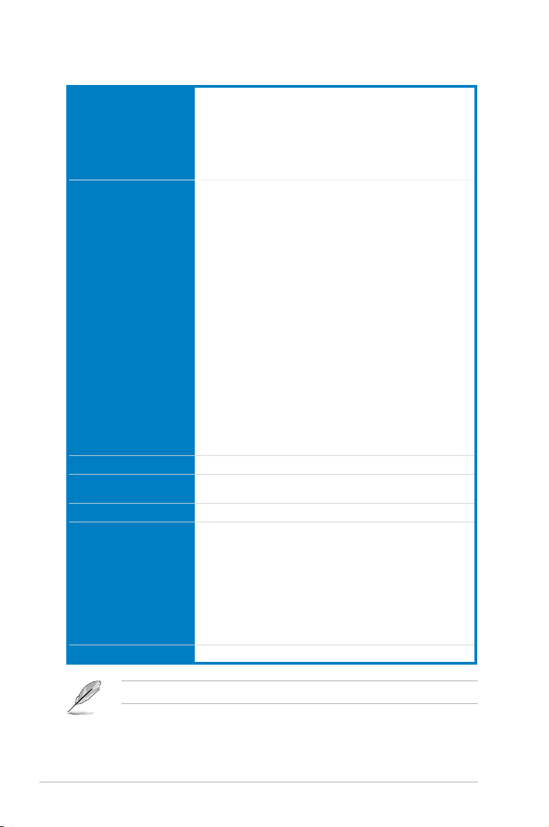
Storage
LAN
Wireless Data Network
Bluetooth
Audio
USB
Intel® Z87 Express Chipset:
6 x SATA 6.0 Gb/s ports*
®
— Intel
Rapid Storage 12 supports RAID 0, 1, 5, and 10
®
— Intel
Smart Response Technology, Intel® Rapid Start
Technology, and Intel® Smart Connect Technology**
1 x M.2 (NGFF) SSD Slot B on mPCIe Combo II expansion card
— Supports PCI Express 2.0 x1 and SATA 6Gb/s standard
— Supports M.2 (NGFF) Type 2242 (22mm x 42mm) SSD card
ASMedia® SATA 6Gb/s controller:
— 4 x SATA 6.0 Gb/s ports ***
* SATA 6Gb/s port 5 will be disabled when M.2 (NGFF) slot on mPCIe
Combo II is in use.
** The functions supported depends on the CPU types.
*** These SATA ports are for data hard drives only. ATAPI devices are not
supported.
1 x Intel® I217-V Gigabit LAN Controller
Wi-Fi 802.11 a/b/g/n/ac supports dual frequency band 2.4/5 GHz
* The module is pre-installed on the mPCIe Combo II expansion card.
Bluetooth v4.0/3.0+HS
* The module is pre-installed on the mPCIe Combo II expansion card.
Realtek® ALC1150 8-Channel High Denition Audio
CODEC
— Supports jack-detection, multi-streaming, front panel jackretasking
— Content Protection for Full Rate lossless DVD Audio, Blu-ray
DVD, and HD-DVD audio content playback
— Optical S/PDIF output port at back panel
Intel® Z87 Express Chipset
— 4 x USB 3.0 ports (2 ports at mid-board [blue], 2 ports at back
panel [red] with ASUS USB 3.0 Boost support*)
— 8 x USB 2.0 ports (2 ports at back panel, 1 port reserved for
ROG Connect; 6 ports at mid-board**
ASMedia® USB 3.0 SuperSpeed USB HUB controller
— 4 x USB 3.0 ports, 4 ports at back panel [blue]
* The UASP standard for Intel® native USB 3.0 is only supported under
Windows 8® OS.
** 2 x USB2.0 ports at mid-board shares with ROG extension (ROG_EXT)
port.
(continued on the next page)
xi

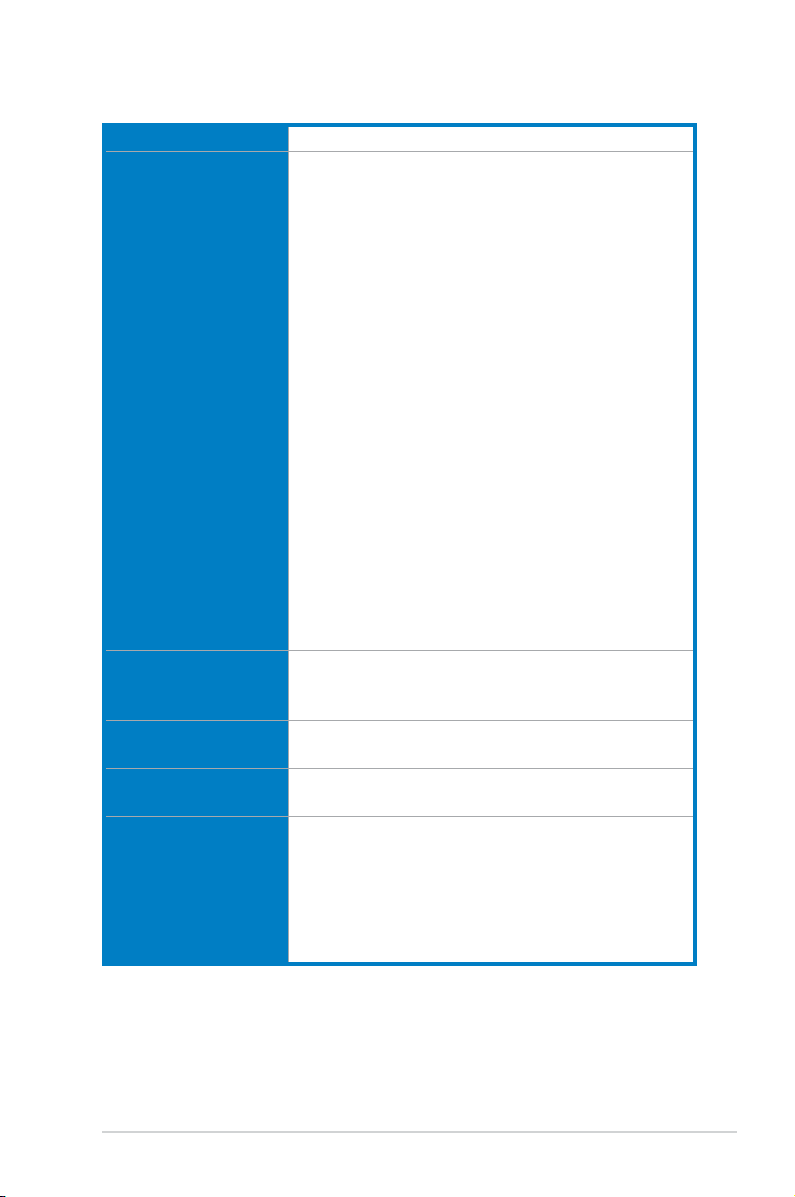
ROG Exclusive Features
Special Features
ROG Extreme OC Kit
— EZ Plug
— LN2 Mode
— Slow Mode
— PCIe x16 Lane switch
ROG Connect
— RC Diagram
— RC Remote
— RC Poster
ROG Extreme Engine Digi+ III
— Full digital 8+2 phase CPU/DRAM power
TM
— NexFET
Power Block MOSFET
— 60A BlackWing Chokes
— 10K Black Metallic Capacitors
mPCIe Combo II (mPCIe/M.2 (NGFF) combo card)
UEFI BIOS features
— ROG BIOS Print
— GPU.DIMM Post
— Extreme Tweaker
— Tweaker’s Paradise
— ROG SSD Secure Erase
— O.C. Prole
— ROG Pulse
CPU Level Up
Probelt
ROG RAMDisk
ASUS Dual Intelligent Processors 4
— 4-way Optimization Tuning Key
ASUS EPU
ASUS Wi-Fi GO!
ASUS Exclusive Features
— AI Suite III
— TurboV EVO
— DIGI+ Power Control
— Fan Xpert 2
— USB 3.0 Boost
— GPU Boost
— AI Charger+
— USB Charger+
— Disk Unlocker
(continued on the next page)
xii

Special Features
Back I/O Ports
Internal Connectors
ASUS EZ DIY
— ASUS BIOS Flashback
— ASUS CrashFree BIOS 3
— ASUS EZ Flash 2
— ASUS C.P.R. (CPU Parameter Recall)
ASUS Q-Design
— ASUS Q-Code
— ASUS Q-Shield
— ASUS Q-Connector
— ASUS Q-LED (CPU, DRAM, VGA, Boot Device LED)
— ASUS Q-Slot
— ASUS Q-DIMM
1 x Clear CMOS button
1 x ROG Connect button
2 x USB 2.0 ports (1 port can be switched to ROG Connect)
6 x USB 3.0 ports [blue]
1 x LAN (RJ45) port
1 x Optical S/PDIF out
1 x HDMI port
1 x DisplayPort
1 x PS/2 keyboard/mouse combo port
6 x Audio jacks
1 x USB 3.0 connector (supports additional two USB 3.0 ports)
3 x USB 2.0 connectors (support additional six USB 2.0 ports, one
connector via ROG_EXT header)
10 x SATA 6.0 Gb/s connectors
1 x ROG Extension (ROG_EXT) header
1 x 4-pin CPU fan connector for smart DC/PWM mode control
1 x 4-pin CPU optional fan connector
3 x 4-pin Chassis fan connector
3 x 4-pin Optional fan connector
3 x Thermal sensor connectors
1 x 24-pin EATX Power connector
1 x 8-pin EATX 12V Power connector
1 x 4-pin EATX 12V Power connector
1 x 6-pin EZ Plug connector (in black for PCIe slots)
1 x 4-pin EZ Plug connector (in white for back I/O and PCIe slots)
10 x ProbeIt Measurement Points
1 x LN2 Mode jumper
1 x Slow mode switch
1 x Power-on button
1 x Reset button
1 x MemOK! button
1 x BIOS Switch button
1 x S/PDIF out header
(continued on the next page)
xiii
1 x Front panel audio connector (AAFP)
1 x System panel connector
Internal Connectors
Accessory
Manageability WfM2.0, DMI2.0, WOL by PME, PXE
BIOS Features
Manageability WfM2.0, DMI2.0, WOL by PME, PXE
Support DVD contents
Form Factor ATX Form Factor, 12” x 9.6” (30.5cm x 24.4cm)
1 x mPCIe Combo II connector
1 x Directkey button
1 x DRCT (DirectKey) header
1 x FastBoot switch
1 x User’s manual
1 x I/O Shield
OC Panel Kit
— 1 x OC Panel
— 1 x OC Panel 5.25-inch drive bay metal case
— 1 x OC Panel cable
— Set of screws (1 x 2 pcs) ; (1 x 4 pcs)
1 x mPCIe Combo II card with dual-band WiFi 802.11 a/b/g/n/ac +
Bluetooth v4.0/3.0+HS module
1 x 2T2R dual-band Wi-Fi moving antennas
5 x 2-in-1 SATA 6Gb/s signal cables
1 x 4-Way SLI® bridge
1 x 3-Way SLI® bridge
1 x SLI® cable
1 x CrossFire™ cable
1 x ROG Connect cable
1 x 2-in-1 ASUS Q-Connector Kit
1 x 12-in-1 ROG Cable Label
1 x ROG Magnet
64 Mb UEFI AMI BIOS, PnP, DMI 2.0, WfM 2.0, SM BIOS 2.5, ACPI
2.0a, Multi-language BIOS
Drivers
ROG RAMDisk
ROG CPU-Z
ROG Mem TweakIt
Kaspersky® Anti-Virus
DAEMON Tools Pro Standard
ASUS WebStorage
ASUS Utilities
xiv
Specications are subject to change without notice.
OC Panel specications summary
Display 2.6-inch LCM
Pure hardware-based overclocking support
Boot debug POST code
Intuitive tuning in two OC modes
— EXTREME Mode for subzero OC benching
— NORMAL Mode for in-chassis usage
Seamless integration with CPU Level Up at one-click OC button
Real-time control and display CPU fan speed, temperature, BCLK
and RATIO
Adjustable system voltages, frequencies on-the-y
Stylish design with 90 plus-degree-tilt movable faceplate
(EXTREME Mode)
Features
I/O Ports
Power
Installation
Requirements
Compatibility
FanSpeed Control button*
— Standard/Silent/Turbo mode
Four (4) additional 4-pin fan headers
LCM backlight on/off
ROG exclusive features
— VGA Hotwire
— Subzero Sense
— Slow Mode
— Pause Switch
— VGA SMB header
— ProbeIt
* FanSpeed Control button supports 4-pin CPU fan only.
POWER : 1 x SATA power connector
ROG_EXT port : 1 x 18-1 pin data connection port
FAN : 4 x 4-pin extra Fan connectors
Voltage : +12V, +5V, +5VSB
Power consumption : 5A
1 x 5.25-inch drive bay required for NORMAL Mode installation
1 x SATA power cable from system power supply
Maximus VI Series and other motherboards with ROG_EXT port
*Visit the ASUS website at www.asus.com for the latest motherboard
support/compatibility lists.
**Please install the latest utility/rmware (ROG PLUS) for better
compatibility.
***Update the motherboard BIOS to the latest version for better
compatibility with OC Panel.
xv

Package contents
Check your motherboard package for the following items.
Motherboard
Cables 1 x ROG Connect cable
Accessories
Application DVD
Documentation
If any of the above items is damaged or missing, contact your retailer.
ROG MAXIMUS VI EXTREME
5 x 2-in-1 SATA 6.0 Gb/s signal cables
1 x 4-WAY SLI® bridge
1 x 3-WAY SLI® bridge
1 x SLI® cable
1 x CrossFireTM cable
1 x ROG_EXT cable
1 x I/O Shield
1 x OC Panel
1 x OC Panel 5.25-inch drive bay metal case
1 x mPCIe Combo II card with dual band Wi-Fi / Bluetooth
module
1 x dual band Wi-Fi Moving Antenna
1 x 12-in-1 ROG cable label
1 x 2-in-1 ASUS Q-Connector kit
1 x ROG Magnet
ROG motherboard support DVD
User guide
xvi
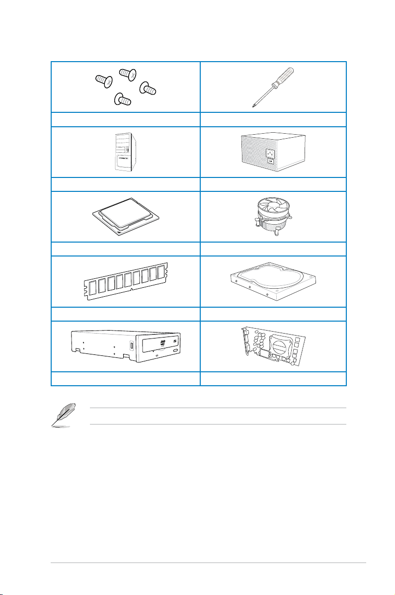
Installation tools and components
1 bag of screws Philips (cross) screwdriver
PC chassis Power supply unit
Intel LGA 1150 CPU Intel LGA 1150 compatible CPU Fan
DDR3 DIMM SATA hard disk drive
SATA optical disc drive (optional) Graphics card (optional)
The tools and components in the table above are not included in the motherboard package.
xvii

xviii

Chapter 1: Product Introduction
Product introduction
1
1.1 Special features
1.1.1 Product highlights
Republic of Gamers
The Republic of Gamers offers you the best of the best. We offer the best hardware
engineering, the fastest performance, the most innovative ideas, and we welcome the best
gamers to join in. In the Republic of Gamers, mercy rules are only for the weak, and bragging
rights means everything. We believe in making statements and we excel in competitions.
If your character matches our trait, then join the elite Republic of Gamers and make your
presence felt.
LGA1150 socket for 4th Generation Intel® Core™ i7 / Intel
®
Intel
Core™ i3, Pentium® and Celeron® Processors
This motherboard supports 4th generation Intel® Core™ i7/ Intel® Core™ i5/ Intel® Core™
i3, Pentium® and Celeron® processors in the LGA1150 package. It provides great graphics
and system performance with its GPU, dual-channel DDR3 memory slots, and PCI Express
2.0/3.0 expansion slots.
Intel® Z87 Express Chipset
Intel® Z87 Express Chipset is a single-chipset that supports the LGA1150 socket 4th
generation Intel® Core™ i7/ Intel® Core™ i5/ Intel® Core™ i3, Pentium® and Celeron®
processors. It utilizes the serial point-to-point links, which increases bandwidth and enhances
the system’s performance. It natively supports up to six USB 3.0 ports for up to ten times
faster transfer rate than USB 2.0, and enables the iGPU function for Intel® integrated graphics
performance.
PCI Express® 3.0
PCI Express® 3.0 (PCIe 3.0) is the PCI Express bus standard that provides twice the
performance and speed of PCIe 2.0. It provides an optimal graphics performance,
unprecedented data speed, and seamless transition with its complete backward compatibility
to PCIe 1.0/2.0 devices.
SLI®/CrossFire™ On-Demand
This motherboard features a unique PCIe 3.0 bridge chip to support multi-GPU SLI®/
CrossFireX™ graphics cards for an unrivaled gaming performance. With the Intel
platform to optimize the PCIe allocation of multiple GPUs, it supports up to 4-WAY GPU SLI
or CrossFireX™ conguration.
®
Core™ i5 /
®
Z87
®
ASUS MAXIMUS VI EXTREME
Chapter 1
1-1

1.1.2 ROG Intelligent Performance & Overclocking features
mPCIe Combo II
ROG mPCIe Combo II offers expandability solutions with the latest connectivity standards via
the proprietary connector onboard. It provides your system with the fastest Wi-Fi 802.11ac
and Bluetooth 4.0 connection. It also features the M.2 (NGFF) slot for an optimal system
performance.
ROG Connect
ROG Connect allows you to monitor the status of your desktop PC and tweak its parameters
in real-time via a notebook. ROG Connect links your main system to a notebook through a
USB cable, allowing you to view real-time POST code and hardware status readouts on your
notebook, as well as make on-the-y parameter adjustments at a purely hardware level.
Extreme Engine Digi+ III
The Extreme Engine Digi+ III offers the best CPU/Memory design on the Z87® motherboard.
It is equipped with NexFET
up to 90% efciency under normal operation. The BlackWing Chokes handles pressures with
ease. The Black Metallic solid capacitor lasts ve times longer than the generic capacitors
with better low temperature tolerance. Altogether making it the perfect motherboard for
overclocking.
iROG
The iROG is a special IC that fully maximizes ROG’s unique functions, providing you with full
control of your motherboard at any stage. It greatly increases your overclocking enjoyment,
and offers you with advanced system control and management features purely at a hardware
level.
CPU Level Up
With ROG’s CPU Level Up, overclocking has never been so easy, or cost-free. Simply select
the processor that you want to overclock to, and the motherboard will do the rest.
USB BIOS FlashBack
USB BIOS Flashback offers a hassle-free updating solution for your ultimate convenience.
Simply install a USB storage device containing the BIOS le, press the BIOS Flashback
button for three seconds, and the UEFI BIOS is automatically updated even without entering
the existing the BIOS or operating system. It also allows you to regularly check for UEFI
BIOS updates, and download the latest BIOS automatically.
GPU.DIMM Post
Chapter 1
GPU.DIMM Post enables you to catch potential problems even before you enter the OS,
saving you valuable time in detecting component failure under extreme conditions. With GPU.
DIMM Post, quickly and easily check your graphic cards, memory modules’ statuses in the
BIOS, and overclocking settings.
BIOS Print
ROG offers a whole new UEFI BIOS feature to handle the demands of an overclocking
experience. The motherboard features ROG BIOS Print that allows you to easily share your
BIOS settings to others with the press of a button.
TM
Power Block MOSFET that offers great durability and provides
1-2
Chapter 1: Product introduction

ProbeIt
This motherboard consists of eleven (11) ProbeIt measurement points that helps you detect
your system’s current voltage. With the use of a multimeter device, these points can help
measure your system’s Vcore, PCH, IO (Digital/Analog), DRAM, iGPU, System agent and
other critical voltages.
Extreme Tweaker
Extreme Tweaker is the one stop shop to ne-tune your system to optimal performance.
With Extreme Tweaker, you can adjust the system settings such as frequency, over-voltage,
memory timing, and more.
Loadline Calibration
Maintaining ample voltage support for the CPU is critical during overclocking. The
Loadline Calibration ensures stable and optimal CPU voltage under heavy loading. It helps
overclockers enjoy the motherboard’s ultimate OC capabilities and benchmark scores.
BIOS Flashback
BIOS Flashback gives you the ability to save two versions of BIOS simultaneously: one
saved BIOS for the tweaked overclocking setting, and one saved BIOS from the previous
version.
OC Panel
Overclocking made easier than ever! No more messing with the BIOS, OS, or software
utilities. OC Panel is the next step in dedicated direct tweaking. It works inside the case or as
an external console, and features normal mode with info covering CPU temps, ratios, base
clocks, and CPU fan speed. With one press of the CPU Level Up button you can instantly
apply custom proles designed by the world’s leading overclockers, while FanSpeed Control
modies blower RPMs. In extreme mode, some of the most commonly used voltage tuning
settings are offered, along with Subzero Sense and VGA Hotwire, giving you eld access to
super-cool liquid thermal temp readings and streamlined hardware-level GPU overvolting.
ASUS MAXIMUS VI EXTREME
Chapter 1
1-3

1.1.3 ASUS special features
Wi-Fi GO!
ASUS Wi-Fi GO! leads the way to a more enjoyable home entertainment. With ASUS Wi-Fi
GO!, you can wirelessly stream media les to DLNA devices, remotely control and access
your computer using your mobile device, and easily transfer les between your computer and
mobile device.
Conveniently use and enjoy these ASUS Wi-Fi GO! functions:
Cloud GO!: Allows you to control les and sync them all across cloud services in a few
•
clicks.
•
DLNA Media Hub: Provides support to the latest DLNA standard, and allows you to
•
stream media les to a DLNA-supported device.
Remote Desktop: Allows you to view your computer’s desktop and remotely operate
•
your computer in real-time from your mobile device.
Remote Keyboard and Mouse: Allows you to use your mobile device’s touch panel as a
•
remote keyboard and mouse for your computer.
Smart Motion Control: Allows you to remotely control your computer using your mobile
•
device’s customized gestures.
File Transfer: Allows you to transfer les between your computer and mobile device.
•
Capture and Send: Allows you to take screenshots and send them to a mobile device.
•
1.1.4 ROG-rich bundled software
Kaspersky® Anti-Virus
Kaspersky® Anti-Virus Personal offers premium antivirus protection for individual users and
home ofces. It is based on advanced antivirus technologies. The product incorporates the
Kaspersky® Anti-Virus engine, which is renowned for malicious program detection rates that
are among the industry’s highest.
DAEMON Tools Pro Standard
DAEMON Tools Pro offers essential functionality to backup CD, DVD and Blu-ray discs. It
converts optical media into virtual discs and emulates devices to work with the virtual copies.
DAEMON Tools Pro organizes data, music, video, and photo collections on a PC, notebook,
or netbook.
ROG CPU-Z
ROG CPU-Z, authorized by Intel’s CPU Identication (CPUID), is a customized ROG utility
that allows you to gather information about your system’s main components. It gives you
Chapter 1
the current information and status of your CPU, motherboard, memory, and other main
components. Get that ROG look of reporting your system’s current information with ROG
CPU-Z.
MemTweakIt
MemTweakIt is a DRAM efciency tool that allows you to ne-tune your DRAM in real time
and allows you to post and share your DRAM conguration scores to the ROG website.
1-4
Chapter 1: Product introduction

ROG RAMDisk
RAMDisk reserves part of system memory and turns it into actual storage, so you can
place favorite app and game cache les in it to enjoy high-speed RAM performance while
accessing them. Plus, this extends SSD lifespan and keeps your main storage optimized for
really important tasks, and you get auto data backup and restore.
ASUS MAXIMUS VI EXTREME
Chapter 1
1-5

1.2 Motherboard overview
1.2.1 Before you proceed
Take note of the following precautions before you install motherboard components or change
any motherboard settings.
• Unplug the power cord from the wall socket before touching any component.
• Before handling components, use a grounded wrist strap or touch a safely grounded
object or a metal object, such as the power supply case, to avoid damaging them due
to static electricity.
• Hold components by the edges to avoid touching the ICs on them.
• Whenever you uninstall any component, place it on a grounded antistatic pad or in the
bag that came with the component.
• Before you install or remove any component, ensure that the ATX power supply is
switched off or the power cord is detached from the power supply. Failure to do so
may cause severe damage to the motherboard, peripherals, or components.
Chapter 1
1-6
Chapter 1: Product introduction
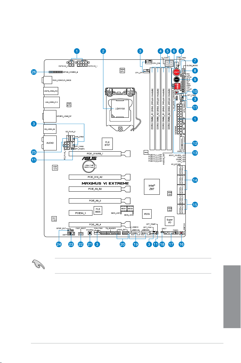
1.2.2 Motherboard layout
Refer to 1.2.9 Internal connectors and 2.3.1 Rear I/O connection for more information
about rear panel connectors and internal connectors.
ASUS MAXIMUS VI EXTREME
Chapter 1
1-7

Layout contents
Connectors/Jumpers/Buttons and switches/Slots Page
1. Power connectors (24-pin EATXPWR, 8-pin EATX12V, 4-pin EATX12V) 1-43
2. LGA1150 CPU Socket
3. CPU, chassis, and optional fan connectors (4-pin CPU_FAN, 4-pin
CPU_OPT, 4-pin OPT_FAN1-3, 4-pin CHA_FAN1-3)
4. DDR3 DIMM slots
5. Q_Code LEDs
6. PCIe x16 Lane switch
7. START (Power-on) button
8. Slow Mode switch
9. RESET button
10. MemOK! button
11. Thermal sensor cable connectors (2-pin OPT_TEMP1-3)
12. USB 3.0 connectors (20-1 pin USB3_12)
13. LN2 Mode header
14. Intel® Z87 Serial ATA 6.0 Gb/s connectors (7-pin SATA6G_1-6 [red])
15. ASMedia® Serial ATA 6.0 Gb/s connectors (7-pin SATA6G_E12/E34 [red])
16. BIOS Switch button
17. System panel connector (20-8 pin PANEL)
18. DRCT connector
19. USB 2.0 connectors (10-1 pin USB910; USB1112; USB1314)
20. ROG Extension connector (18-1 pin ROG_EXT)
21. DirectKey button
22. Fastboot switch
23. Front panel audio connector (10-1 pin AAFP)
24. Digital audio connector (4-1 pin SPDIF_OUT)
25. EZ Plug connectors (6-pin EZ_PLUG_1; 4-pin EZ_PLUG_2)
26. mPCIe Combo II slot (MPCIE_COMBO_II)
1-9
1-41
1-10
1-30
1-25
1-22
1-24
1-22
1-23
1-45
1-38
1-27
1-37
1-38
1-24
1-44
1-46
1-40
1-47
1-26
1-25
1-42
1-39
1-45
1-46
Chapter 1
1-8
Chapter 1: Product introduction
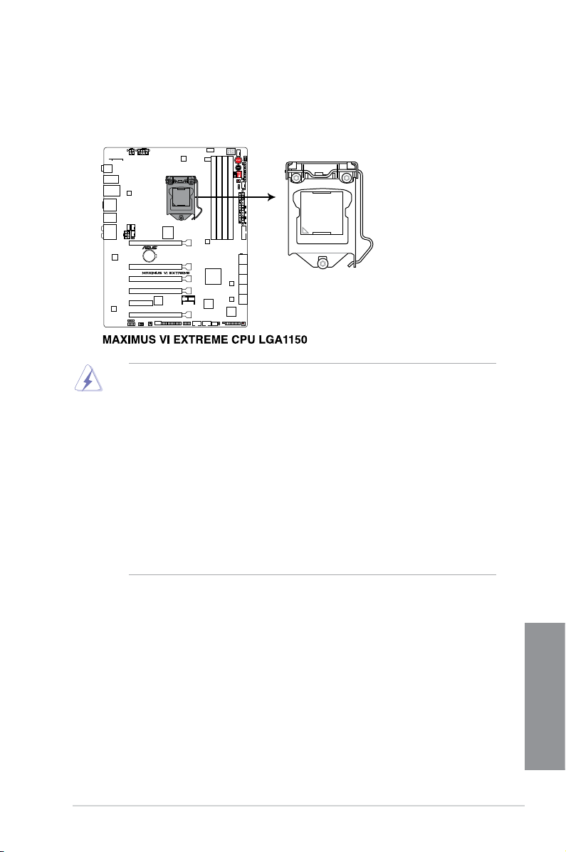
1.2.3 Central Processing Unit (CPU)
The motherboard comes with a surface mount LGA1150 socket designed for the 4th
Generation Intel® Core™ i7 / Intel® Core™ i5 / Intel® Core™ i3, Pentium®, and Celeron®
processors.
• Ensure that all power cables are unplugged before installing the CPU.
• Ensure that you install the correct CPU designed for LGA1150 only. DO NOT install a
CPU designed for LGA1155 and LGA1156 sockets on the LGA1150 socket.
• Upon purchase of the motherboard, ensure that the PnP cap is on the socket and
the socket contacts are not bent. Contact your retailer immediately if the PnP cap
is missing, or if you see any damage to the PnP cap/socket contacts/motherboard
components. ASUS will shoulder the cost of repair only if the damage is shipment/
transit-related.
• Keep the cap after installing the motherboard. ASUS will process Return Merchandise
Authorization (RMA) requests only if the motherboard comes with the cap on the
LGA1150 socket.
• The product warranty does not cover damage to the socket contacts resulting from
incorrect CPU installation/removal, or misplacement/loss/incorrect removal of the PnP
cap.
ASUS MAXIMUS VI EXTREME
Chapter 1
1-9
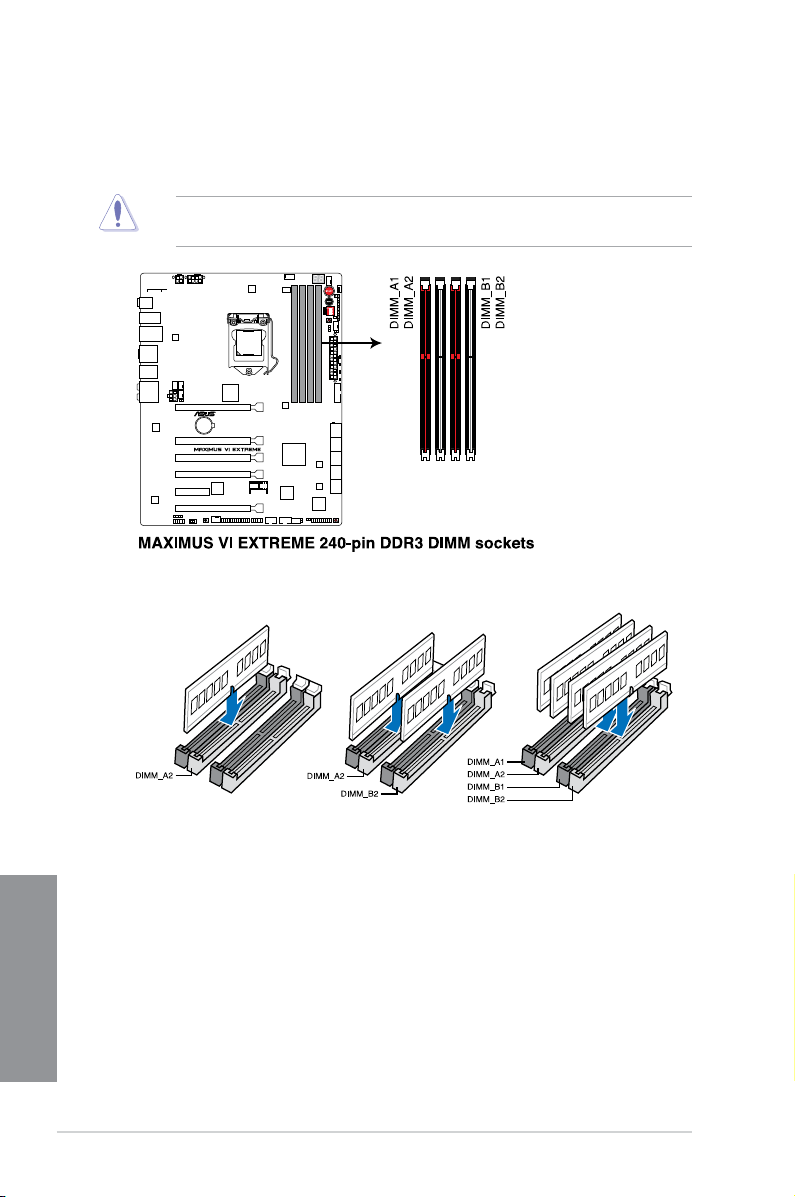
1.2.4 System memory
The motherboard comes with four Double Data Rate 3 (DDR3) Dual Inline Memory Modules
(DIMM) slots.
A DDR3 module is notched differently from a DDR or DDR2 module. DO NOT install a DDR
or DDR2 memory module to the DDR3 slot.
Recommended memory congurations
Chapter 1
1-10
Chapter 1: Product introduction

Memory congurations
You may install 1GB, 2GB, 4GB and 8GB unbuffered and non-ECC DDR3 DIMMs into the
DIMM sockets.
• Memory module with memory frequency higher than 2133 MHz and its corresponding
timing or the loaded XMP prole is not the JEDEC memory standard. The stability and
compatibility of these memory modules depend on the CPU’s capabilities and other
installed devices.
• You may install varying memory sizes in Channel A and Channel B. The system maps
the total size of the lower-sized channel for the dual-channel conguration. Any excess
memory from the higher-sized channel is then mapped for single-channel operation.
• According to Intel CPU spec, DIMM voltage below 1.65V is recommended to protect
the CPU.
• Always install DIMMs with the same CAS latency. For optimal compatibility, we
recommend that you install memory modules of the same version or date code (D/C)
from the same vendor. Check with the retailer to get the correct memory modules.
• Due to the memory address limitation on 32-bit Windows OS, when you install 4GB
or more memory on the motherboard, the actual usable memory for the OS can be
about 3GB or less. For effective use of memory, we recommend that you do any of the
following:
a) Use a maximum of 3GB system memory if you are using a 32-bit Windows OS.
b) Install a 64-bit Windows OS when you want to install 4GB or more on the
motherboard.
c) For more details, refer to the Microsoft
com/kb/929605/en-us.
• This motherboard does not support DIMMs made up of 512Mb (64MB) chips or less
(Memory chip capacity counts in Megabit, 8 Megabit/Mb = 1 Megabyte/MB).
®
support site at http://support.microsoft.
• The default memory operation frequency is dependent on its Serial Presence Detect
(SPD), which is the standard way of accessing information from a memory module.
Under the default state, some memory modules for overclocking may operate at a
lower frequency than the vendor-marked value. To operate at the vendor-marked or at
a higher frequency, refer to section 3.3 Extreme Tweaker menu for manual memory
frequency adjustment.
• For system stability, use a more efcient memory cooling system to support a full
memory load (4 DIMMs) or overclocking condition.
ASUS MAXIMUS VI EXTREME
Chapter 1
1-11
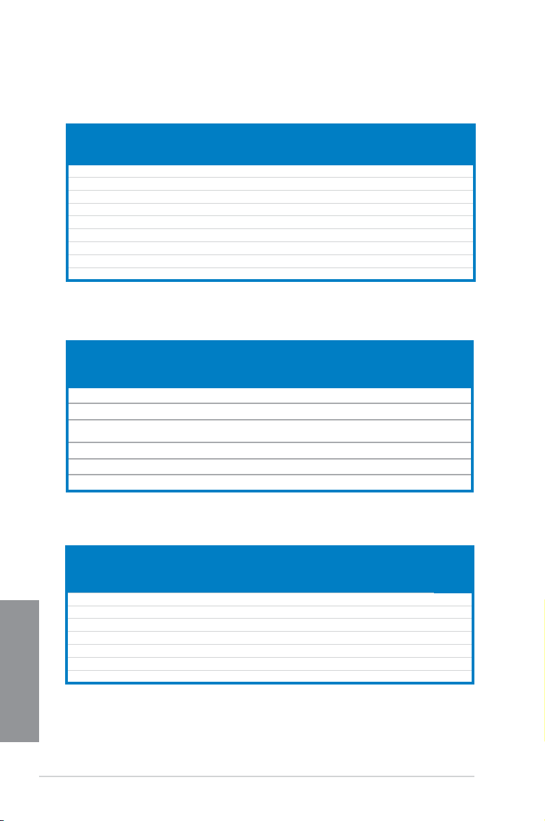
MAXIMUS VI EXTREME Motherboard Qualied Vendors Lists (QVL)
DDR3 2800 MHz capability
DIMM socket
Vendors Part No. Size
AVEXIR AVD3U28001204G-4CI 16GB (4x4GB) DS — — 12-14-14-35 1.65V • •
CORSAIR CMD16GX3M4A2800C11 16GB (4x4GB) DS — — 11-14-14-35 1.65V • •
CORSAIR CMD16GX3M4A2800C12 16GB (4x4GB) DS — — 12-14-14-36 1.65V • •
G.SKILL F3-2800C11D-8GTXD 8GB (2x4GB) DS — — 11-13-13-35 1.65V • •
G.SKILL F3-2800C11Q-16GTXD 16GB (4x4GB) DS — — 11-13-13-35 1.65V • •
G.SKILL F3-2800C11D-8GTXDG 8GB (2x4GB) DS — — 11-14-14-35 1.65V • •
G.SKILL F3-2800C11Q-16GTXDG 16GB (4x4GB) DS — — 11-13-13-35 1.65V • •
G.SKILL F3-2800C12Q-32GTXG 32GB (4x8GB) DS — — 12-13-13-35 1.65V • •
G.SKILL F3-2800C10D-8GBTXD 8GB (2x4GB) DS — — 10-13-13-35 1.65V • •
SS/DSChip
Brand
Chip
Timing Voltage
NO.
support
(Optional)
2 4
DDR3 2666 MHz capability
DIMM socket
Vendors Part No. Size
Apacer 78.BAGFR.AFD0C(XMP) 8GB (2x 4GB) DS — — 12-13-13-35 — • •
Apacer 78.CAGFF.AFD0C(XMP) 16GB (2x 8GB) DS — — 12-13-13-35 — • •
G.SKILL F3-2666CL10Q-
16GBZHD(XMP)
GEIL GOC332GB2666C11QC(XMP) 32GB (4x 8GB) DS — — 11-13-13-32 1.65 • •
Team TXD34G2666HC11CBK(XMP) 8GB (2x 4GB) SS — — 11-13-13-35 1.65 • •
Team TXD38G2666HC11CBK(XMP) 16GB (2x 8GB) DS — — 11-13-13-35 1.65 •
16GB (4x 4GB) DS — — 10-12-12-31 1.65 •
SS/
DS
Chip
Chip
NO.
Timing
support
(Optional)
2 4
DDR3 2400 MHz capability
Vendors Part No. Size
CORSAIR CMGTX8(XMP) 8GB (4x2GB) SS — — 10-12-10-30 1.65 • •
CORSAIR CMZ16GX3M2A2400C10 (Ver4.21) 16GB (2x8GB) DS — — 10-12-12-31 1.65 •
Chapter 1
GEIL GOC316GB2400C10QC(XMP) 16GB (4x4GB) DS — — 10-11-11-30 1.65 • •
GEIL GOC316GB2400C11QC(XMP) 16GB (4x4GB) DS — — 11-11-11-30 1.65 • •
KINGSTON KHX24C11K4/16X(XMP) 16GB (4x4GB) DS — — 11-13-13-30 1.65 • •
KINGSTON KHX24C11T2K2/8X(XMP) 8GB (2x4GB) DS — — — 1.65 •
Patriot PXD38G2400C11K(XMP) 8GB (2x4GB) DS — — 2400 11-11-11-30 1.65 •
1-12
SS/DSChip
Brand
DIMM
Chip
Timing Voltage
NO.
socket
support
(Optional)
2 4
Chapter 1: Product introduction
Loading…
View the manual for the Asus MAXIMUS VI EXTREME here, for free. This user manual comes under the category motherboards and has been rated by 2 people with an average of a 8.4. This manual is available in the following languages: English. Do you have a question about the Asus MAXIMUS VI EXTREME?
Ask your question here
Asus MAXIMUS VI EXTREME specifications
Below you will find the product specifications and the manual specifications of the Asus MAXIMUS VI EXTREME.
Supported memory types
DDR3-SDRAM
Processor manufacturer
Intel
PCI Express power connectors (6-pin)
1
General
| Brand | Asus |
| Model | MAXIMUS VI EXTREME | 90MB0DS0-M0EAY0 |
| Product | motherboard |
| Language | English |
| Filetype | User manual (PDF), Installation Guide (PDF) |
Memory
| Supported memory types | DDR3-SDRAM |
| Number of memory slots | 4 |
| Memory slots type | DIMM |
| Memory channels | Dual-channel |
| Supported memory clock speeds | 1333,1500,1600,1666,1800,1866,1900,2000,2100,2133,2200,2250,2400,2450,2600,2666,2800,3000 MHz |
| Maximum internal memory | 32 GB |
| Unbuffered memory | Yes |
Processor
| Processor manufacturer | Intel |
| Compatible processor series | Intel Celeron, Intel Pentium |
| Maximum number of SMP processors | 1 |
| Processor socket | LGA 1150 (Socket H3) |
Internal I/O
| USB 2.0 connectors | 3 |
| USB 3.2 Gen 1 (3.1 Gen 1) connectors | 1 |
| S/PDIF out connector | Yes |
| CPU fan connector | Yes |
| ATX Power connector (24-pin) | Yes |
| Number of EATX power connectors | 1 |
| Chassis intrusion connector | Yes |
| Number of chassis fan connectors | 6 |
| Number of Parallel ATA connectors | 0 |
| Front panel audio connector | Yes |
| TPM connector | Yes |
| Number of SATA II connectors | 0 |
| Number of SATA III connectors | 10 |
| Peripheral (Molex) power connectors (4-pin) | 1 |
| EPS power connector (8-pin) | Yes |
Other features
| PCI Express power connectors (6-pin) | 1 |
| Dual Link DVI | Yes |
| Quick installation guide | Yes |
| BIOS switch button | Yes |
Rear panel I/O ports
| USB 2.0 ports quantity | 2 |
| USB 3.2 Gen 1 (3.1 Gen 1) Type-A ports quantity | 6 |
| Ethernet LAN (RJ-45) ports | 1 |
| eSATA ports quantity | 0 |
| PS/2 ports quantity | 1 |
| Firewire (IEEE 1394) ports | 0 |
| Headphone outputs | 6 |
| Microphone in | Yes |
| S/PDIF out port | Yes |
| VGA (D-Sub) ports quantity | 0 |
| DVI-D ports quantity | 0 |
| HDMI ports quantity | 1 |
| DisplayPorts quantity | 1 |
| HDMI version | 1.4a |
Features
| Component for | PC |
| Motherboard chipset family | Intel |
| Motherboard chipset | Intel® Z87 |
| Motherboard form factor | ATX |
| Cooling type | Passive |
| PC health monitoring | CPU, FAN, Temperature |
| Audio output channels | 7.1 channels |
| Audio chip | Realtek ALC1150 |
| Windows operating systems supported | Yes |
| Power source type | ATX |
Storage controllers
| Supported storage drive interfaces | SATA, SATA II, SATA III |
| RAID levels | 0, 1,5, 10 |
Graphics
| Parallel processing technology support | 2-Way CrossFireX, 2-Way SLI, 3-Way CrossFireX, 3-Way SLI, 4-Way CrossFireX, 4-Way SLI, Quad-GPU CrossFireX, Quad-GPU SLI |
| On-board graphics card | Yes |
| Graphics card | HD Graphics |
| HDCP | Yes |
| Graphics card family | Intel |
| Maximum resolution | 4096 x 2160 pixels |
| Discrete graphics support | Yes |
Processor special features
| Intel® High Definition Audio (Intel® HD Audio) | Yes |
| Processor with Intel Graphics Technology required | Yes |
Expansion slots
| PCI Express x4 slots | 1 |
| PCI Express x16 slots | 5 |
| Mini PCI Express slots | 1 |
| PCI Express slots version | 2.0, 3.0 |
| PCI Express configurations | 1×8, 1×16, 2×8 |
Weight & dimensions
Packaging content
| Cables included | SATA |
| Drivers included | Yes |
Network
| Ethernet LAN | Yes |
| Wi-Fi | Yes |
| Bluetooth | Yes |
| Ethernet interface type | Gigabit Ethernet |
| Wi-Fi standards | 802.11a, Wi-Fi 5 (802.11ac), 802.11b, 802.11g, Wi-Fi 4 (802.11n) |
| Bluetooth version | 4.0 |
BIOS
| BIOS type | EFI AMI |
| BIOS memory size | 64 Mbit |
| ACPI version | 2.0a |
| Clear CMOS jumper | Yes |
| Clear CMOS button | Yes |
show more
Frequently asked questions
Can’t find the answer to your question in the manual? You may find the answer to your question in the FAQs about the Asus MAXIMUS VI EXTREME below.
What is the width of the Asus MAXIMUS VI EXTREME?
The Asus MAXIMUS VI EXTREME has a width of 305 mm.
What is the depth of the Asus MAXIMUS VI EXTREME?
The Asus MAXIMUS VI EXTREME has a depth of 244 mm.
Is the manual of the Asus MAXIMUS VI EXTREME available in English?
Yes, the manual of the Asus MAXIMUS VI EXTREME is available in English .
Is your question not listed? Ask your question here
Справочник Пользователя (English)Справочник Пользователя (English)Справочник Пользователя (English)Справочник Пользователя (English)Справочник Пользователя (中文(zhōngwén))Справочник Пользователя (Français)Справочник Пользователя (日本語 (にほんご))Справочник Пользователя (中文(zhōngwén))
Manufacturer:ASUS
Category:Computers & Peripherals
Device:ASUS MAXIMUS VI EXTREME
Name:New_SSD_List
Pages:1
Size:18.19 KB
Manufacturer:ASUS
Category:Computers & Peripherals
Device:ASUS MAXIMUS VI EXTREME
Name:Compatible Model list
Pages:1
Size:185.90 KB
Manufacturer:ASUS
Category:Computers & Peripherals
Device:ASUS MAXIMUS VI EXTREME
Name:M6E_DRAM_QVL
Language:Multilingual
Pages:12
Size:355.23 KB
Manufacturer:ASUS
Category:Computers & Peripherals
Device:ASUS MAXIMUS VI EXTREME
Name:M6E_Devices_QVL_0703
Language:Multilingual
Pages:10
Size:237.70 KB
Manufacturer:ASUS
Category:Computers & Peripherals
Device:ASUS MAXIMUS VI EXTREME
Name:M6E_DRAM_QVL_0717
Language:Multilingual
Pages:13
Size:361.01 KB
Manufacturer:ASUS
Category:Computers & Peripherals
Device:ASUS MAXIMUS VI EXTREME
Name:M6E_H_DRAM_QVL_201406
Language:Multilingual
Pages:1
Size:133.92 KB
Manufacturer:ASUS
Category:Computers & Peripherals
Device:ASUS MAXIMUS VI EXTREME
Name:User’s Manual (French)
Language:Français
Version:F8442
Pages:208
Size:16.74 MB
Manufacturer:ASUS
Category:Computers & Peripherals
Device:ASUS MAXIMUS VI EXTREME
Name:Oc_panel_fw_manual
Version:d135
Pages:5
Size:437.70 KB
Manufacturer:ASUS
Category:Computers & Peripherals
Device:ASUS MAXIMUS VI EXTREME
Name:_ROG_AI_Suite3
Version:DE138
Pages:40
Size:2.37 MB
Manufacturer:ASUS
Category:Computers & Peripherals
Device:ASUS MAXIMUS VI EXTREME
Name:LGA1150 CPU installation Manual
Version:—
Pages:6
Size:2.09 MB
Manufacturer:ASUS
Category:Computers & Peripherals
Device:ASUS MAXIMUS VI EXTREME
Name:User’s Manual (English)
Language:English
Version:E8442
Pages:218
Size:10.47 MB
Manufacturer:ASUS
Category:Computers & Peripherals
Device:ASUS MAXIMUS VI EXTREME
Name:User’s Manual (English)
Language:English
Version:E7948
Pages:208
Size:9.83 MB
Manufacturer:ASUS
Category:Computers & Peripherals
Device:ASUS MAXIMUS VI EXTREME
Name:User’s Manual (Simplified Chinese)
Language:中文(简体)
Pages:208
Size:14.43 MB
Manufacturer:ASUS
Category:Computers & Peripherals
Device:ASUS MAXIMUS VI EXTREME
Name:User’s Manual(Traditional Chinese)
Language:中文(繁體)
Pages:206
Size:14.40 MB
Manufacturer:ASUS
Category:Computers & Peripherals
Device:ASUS MAXIMUS VI EXTREME
Name:User’s Manual (Simplified Chinese)
Language:中文中文(简体)
Version:C7948
Pages:208
Size:14.43 MB
Manufacturer:ASUS
Category:Computers & Peripherals
Device:ASUS MAXIMUS VI EXTREME
Name:User’s Manual (Japanese)
Language:日本語
Version:J7948
Pages:202
Size:9.31 MB
Manufacturer:ASUS
Category:Computers & Peripherals
Device:ASUS MAXIMUS VI EXTREME
Name:User’s Manual(Traditional Chinese)
Language:中文中文(繁體)
Version:T7948
Pages:206
Size:14.40 MB