
A68HM Series
E9808_A68HM Series_Manual.indb 1 2014/10/16 10:08:57

ii
E9808
First Edition
October 2014
Copyright © 2014 ASUSTeK COMPUTER INC. All Rights Reserved.
No part of this manual, including the products and software described in it, may be reproduced,
transmitted, transcribed, stored in a retrieval system, or translated into any language in any form or by any
means, except documentation kept by the purchaser for backup purposes, without the express written
permission of ASUSTeK COMPUTER INC. (“ASUS”).
Product warranty or service will not be extended if: (1) the product is repaired, modied or altered, unless
such repair, modication of alteration is authorized in writing by ASUS; or (2) the serial number of the
product is defaced or missing.
ASUS PROVIDES THIS MANUAL “AS IS” WITHOUT WARRANTY OF ANY KIND, EITHER EXPRESS
OR IMPLIED, INCLUDING BUT NOT LIMITED TO THE IMPLIED WARRANTIES OR CONDITIONS OF
MERCHANTABILITY OR FITNESS FOR A PARTICULAR PURPOSE. IN NO EVENT SHALL ASUS, ITS
DIRECTORS, OFFICERS, EMPLOYEES OR AGENTS BE LIABLE FOR ANY INDIRECT, SPECIAL,
INCIDENTAL, OR CONSEQUENTIAL DAMAGES (INCLUDING DAMAGES FOR LOSS OF PROFITS,
LOSS OF BUSINESS, LOSS OF USE OR DATA, INTERRUPTION OF BUSINESS AND THE LIKE),
EVEN IF ASUS HAS BEEN ADVISED OF THE POSSIBILITY OF SUCH DAMAGES ARISING FROM ANY
DEFECT OR ERROR IN THIS MANUAL OR PRODUCT.
SPECIFICATIONS AND INFORMATION CONTAINED IN THIS MANUAL ARE FURNISHED FOR
INFORMATIONAL USE ONLY, AND ARE SUBJECT TO CHANGE AT ANY TIME WITHOUT NOTICE,
AND SHOULD NOT BE CONSTRUED AS A COMMITMENT BY ASUS. ASUS ASSUMES NO
RESPONSIBILITY OR LIABILITY FOR ANY ERRORS OR INACCURACIES THAT MAY APPEAR IN THIS
MANUAL, INCLUDING THE PRODUCTS AND SOFTWARE DESCRIBED IN IT.
Products and corporate names appearing in this manual may or may not be registered trademarks or
copyrights of their respective companies, and are used only for identication or explanation and to the
owners’ benet, without intent to infringe.
Offer to Provide Source Code of Certain Software
This product contains copyrighted software that is licensed under the General Public License (“GPL”),
under the Lesser General Public License Version (“LGPL”) and/or other Free Open Source Software
Licenses. Such software in this product is distributed without any warranty to the extent permitted by the
applicable law. Copies of these licenses are included in this product.
Where the applicable license entitles you to the source code of such software and/or other additional data,
you may obtain it for a period of three years after our last shipment of the product, either
(1) for free by downloading it from http://support.asus.com/download
or
(2) for the cost of reproduction and shipment, which is dependent on the preferred carrier and the location
where you want to have it shipped to, by sending a request to:
ASUSTeK Computer Inc.
Legal Compliance Dept.
15 Li Te Rd.,
Beitou, Taipei 112
Taiwan
In your request please provide the name, model number and version, as stated in the About Box of the
product for which you wish to obtain the corresponding source code and your contact details so that we
can coordinate the terms and cost of shipment with you.
The source code will be distributed WITHOUT ANY WARRANTY and licensed under the same license as
the corresponding binary/object code.
This offer is valid to anyone in receipt of this information.
ASUSTeK is eager to duly provide complete source code as required under various Free Open Source
Software licenses. If however you encounter any problems in obtaining the full corresponding source
code we would be much obliged if you give us a notication to the email address gpl@asus.com, stating
the product and describing the problem (please DO NOT send large attachments such as source code
archives, etc. to this email address).
E9808_A68HM Series_Manual.indb 2 2014/10/16 10:08:57

iii
Contents
Safety information ………………………………………………………………………………………… iv
About this guide …………………………………………………………………………………………… iv
Package contents …………………………………………………………………………………………. vi
A68HM Series specifications summary …………………………………………………………. vi
Product introduction
1.1 Before you proceed …………………………………………………………………………..1-1
1.2 Motherboard overview ………………………………………………………………………1-1
1.3 Accelerated Processing Unit (APU) ……………………………………………………1-3
1.4 System memory ………………………………………………………………………………..1-6
1.5 Expansion slots ……………………………………………………………………………….. 1-9
1.6 Headers ………………………………………………………………………………………….1-10
1.7 Connectors ……………………………………………………………………………………..1-11
1.8 Software support ……………………………………………………………………………. 1-19
BIOS information
2.1 Managing and updating your BIOS …………………………………………………….2-1
2.2 BIOS setup program ………………………………………………………………………….2-6
2.3 My Favorites ……………………………………………………………………………………..2-9
2.4 Main menu ………………………………………………………………………………………2-10
2.5 Ai Tweaker menu …………………………………………………………………………….2-11
2.6 Advanced menu ………………………………………………………………………………2-12
2.7 Monitor menu ………………………………………………………………………………….2-12
2.8 Boot menu ………………………………………………………………………………………2-13
2.9 Tools menu …………………………………………………………………………………….2-14
2.10 Exit menu ……………………………………………………………………………………….2-14
Appendices
Notices ……………………………………………………………………………………………………… A-1
ASUS contact information ………………………………………………………………………….. A-4
E9808_A68HM Series_Manual.indb 3 2014/10/16 10:08:57
iv
Safety information
Electrical safety
• To prevent electrical shock hazard, disconnect the power cable from the electrical outlet
before relocating the system.
• When adding or removing devices to or from the system, ensure that the power cables
for the devices are unplugged before the signal cables are connected. If possible,
disconnect all power cables from the existing system before you add a device.
• Before connecting or removing signal cables from the motherboard, ensure that all
power cables are unplugged.
• Seek professional assistance before using an adapter or extension cord. These devices
could interrupt the grounding circuit.
• Ensure that your power supply is set to the correct voltage in your area. If you are not
sure about the voltage of the electrical outlet you are using, contact your local power
company.
• If the power supply is broken, do not try to x it by yourself. Contact a qualied service
technician or your retailer.
Operation safety
• Before installing the motherboard and adding devices on it, carefully read all the manuals
that came with the package.
• Before using the product, ensure all cables are correctly connected and the power
cables are not damaged. If you detect any damage, contact your dealer immediately.
• To avoid short circuits, keep paper clips, screws, and staples away from connectors,
slots, sockets and circuitry.
• Avoid dust, humidity, and temperature extremes. Do not place the product in any area
where it may become wet.
• Place the product on a stable surface.
• If you encounter technical problems with the product, contact a qualied service
technician or your retailer.
About this guide
This user guide contains the information you need when installing and conguring the
motherboard.
How this guide is organized
This guide contains the following parts:
• Chapter1:Productintroduction
This chapter describes the features of the motherboard and the new technology it
supports.
• Chapter2:BIOSinformation
This chapter tells how to change system settings through the BIOS Setup menus.
Detailed descriptions of the BIOS parameters are also provided.
E9808_A68HM Series_Manual.indb 4 2014/10/16 10:08:57
v
Where to find more information
Refer to the following sources for additional information and for product and software
updates.
1. ASUS websites
The ASUS website provides updated information on ASUS hardware and software
products. Refer to the ASUS contact information.
2. Optional documentation
Your product package may include optional documentation, such as warranty yers,
that may have been added by your dealer. These documents are not part of the
standard package.
Conventions used in this guide
To ensure that you perform certain tasks properly, take note of the following symbols used
throughout this manual.
DANGER/WARNING: Information to prevent injury to yourself when trying to
complete a task.
CAUTION: Information to prevent damage to the components when trying to
complete a task
IMPORTANT: Instructions that you MUST follow to complete a task. .
NOTE: Tips and additional information to help you complete a task.
Typography
Bold text Indicates a menu or an item to select.
Italics
Used to emphasize a word or a phrase.
<Key> Keys enclosed in the less-than and greater-than sign
means that you must press the enclosed key.
Example: <Enter> means that you must press the Enter or
Return key.
<Key1> + <Key2> + <Key3> If you must press two or more keys simultaneously, the key
names are linked with a plus sign (+).
E9808_A68HM Series_Manual.indb 5 2014/10/16 10:08:57
vi
(continued on the next page)
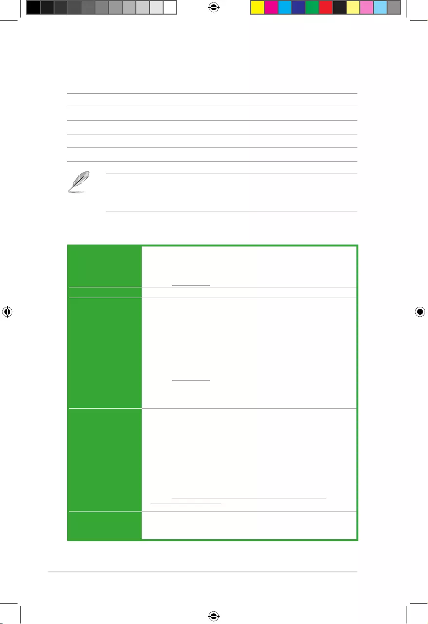
A68HM Series specifications summary
CPU AMD® FM2+ Socket for AMD® A-Series/Athlon™ Series processors
AMD® Turbo Core Technology 3.0 support
Supports APU up to 4 cores
• Refertowww.asus.com for the AMD® CPU support list.
Chipset AMD® A68H FCH
Memory 2 x DIMMs, max. 32GB, DDR3 2400(O.C.)/ 2133/ 1866/ 1600/ 1333 MHz,
non-ECC un-buffered memory
Dual-channel memory architecture
Supports AMD Memory Prole (AMP) memory
• HyperDIMMsupportissubjecttothephysicalcharacteristicsofindividual
CPUs.
• Themaximum32GBmemorycapacitycanbesupportedwith16GBorabove
DIMMs. ASUS will update the memory QVL once the DIMMs are available in the
market.
• Refertowww.asus.com for the latest Memory QVL (Qualified Vendors List).
• Whenyouinstallatotalmemoryof4GBcapacityormore,Windows® 32-bit
operating system may only recognize less than 3GB. We recommend a
maximum of 3GB system memory if you are using a Windows® 32-bit operating
system.
Graphics Integrated AMD® Radeon™ R/HD8000/7000 Series Graphics in the
A-Series APU
Multi-VGA output support: DVI-D and D-Sub
Supports Dual-link DVI with max. resolution 2560×1600@60Hz
Supports D-Sub with max. resolution 1920×1600@60Hz
AMD® Dual Graphics technology support*
Maximum shared memory of 2G
Supports AMD® Dual Graphics technology
• Refertohttp://www.amd.com/us/products/technologies/dual-graphics/
Pages/dual-graphics.aspx#3 for the discrete GPUs which support Dual Graphics
technology.
Storage / RAID AMD® A68H FCH:
— 4 x Serial ATA 6.0Gb/s connectors (Grey) support RAID 0, RAID 1, RAID
10, and JBOD congurations
Package contents
Check your motherboard package for the following items.
Motherboard ASUS A68HM-E / A68HM-K motherboard
Cables 2 x Serial ATA 6.0 Gb/s cables
Accessories 1 x I/O Shield
Application DVD Support DVD
Documentation User Guide
• A68HM series motherboard include A68HM-E and A68HM-K. The layout illustrations
in this user manual are for A68HM-E only.
• If any of the above items is damaged or missing, contact your retailer.
E9808_A68HM Series_Manual.indb 6 2014/10/16 10:08:57
vii
A68HM Series specifications summary
Expansion slots 1 x PCIe 3.0*/2.0 x16 slot
1 x PCIe 2.0 x1 slot
1 x PCI slot
* PCIe 3.0 is supported by FM2+ processors only.
LAN Realtek® 8111GR Gigabit LAN controller
Audio Realtek® ALC887-VD 7.1-channel High Denition Audio CODEC
— LED-lit audio shielding*: Ensures precision analog/digital separation and
greatly reduced multi-lateral interference, with a gorgeous illuminated trace
path
— Special layout design — Separate layers for left and right channels to guard
the quality of the sensitive audio signal
— Premium Japanese-made audio capacitors: Provide warm, natural and
immersive sound with exceptional clarity and delity.
* LED-lit is supported by A68HM-E only.
• UseachassiswithHDaudiomoduleinthefrontpaneltosupporta7.1-channel
audio output.
USB AMD® A68H FCH:
— 2 x USB 3.0 ports (2 ports at back panel, blue)
— 6 x USB2.0 ports (2 ports at back panel; 4 ports at mid-board)
ASUS unique
features ASUS 5X Protection*
— ASUS DIGI+ VRM — 3+2 Phase digital power design
— ASUS Enhanced DRAM Overcurrent Protection — Short circuit damage
prevention
— ASUS ESD Guards — Enhanced ESD protection
— ASUS High Quality 5K-Hour Solid Capacitors — 2.5x long lifespan with
excellent durability
— ASUS Stainless Steel Back I/O — 3x more durable corrosion-resistant
coating
* ASUS 5X Protection Only for A68HM-E
ASUS Exclusive Features
— ASUS EPU
— ASUS USB 3.0 Boost
— ASUS AI Suite 3
— ASUS AI Charger
— ASUS Anti-Surge
ASUS Quiet Thermal Solutions
— ASUS Fanless Design: Stylish heatsink solution
— ASUS Fan Xpert
ASUS EZ DIY
— ASUS UEFI BIOS EZ Mode featuring friendly graphics user interface
— ASUS CrashFree BIOS 3
— ASUS EZ Flash 2
— ASUS MyLogo 2
(continued on the next page)
E9808_A68HM Series_Manual.indb 7 2014/10/16 10:08:57
viii
A68HM Series specifications summary
Specications are subject to change without notice.
Back Panel I/O
ports
1 x PS/2 mouse port (green)
1 x PS/2 keyboard port (purple)
1 x DVI-D port
1 x D-Sub output port
1 x LAN (RJ-45) port
2 x USB 2.0/1.1 ports
2 x USB 3.0 ports
7.1-channel audio I/O ports (3-jack)
Internal I/O
connectors
2 x USB 2.0 connectors support additional 4 USB 2.0 ports
4 x SATA 6.0Gb/s connectors
1 x COM connector
1x TPM header
1 x System panel connector
1 x Internal Speaker connector
1 x 4-pin CPU fan connector
1 x S/PDIF output connector
1 x 4-pin Chassis fan connector
1 x High Denition Front panel audio connector
1 x 24-pin EATX power connector
1 x 4-pin ATX 12V power connector
BIOS 64Mb Flash ROM, NEW UEFI BIOS, PnP, DMI v2.0, WfM2.0, SM BIOS
V2.7, ACPI V2.0a
Support DVD Drivers
ASUS Update
ASUS utilities
Anti-Virus software (OEM version)
Operating System
Support
Windows® 8.1, 32bit/64-bit
Windows® 8, 32bit/64-bit
Windows® 7, 32bit/64-bit
Windows® XP, 32bit
Form factor uATX form factor: 8.9 in x 7.0 in (22.6 cm x 18.0 cm)
E9808_A68HM Series_Manual.indb 8 2014/10/16 10:08:57
1-1
Product introduction
1
1.1 Before you proceed
Take note of the following precautions before you install motherboard components or change
any motherboard settings.
• Unplugthepowercordfromthewallsocketbeforetouchinganycomponent.
• Beforehandlingcomponents,useagroundedwriststraportouchasafelygrounded
objectorametalobject,suchasthepowersupplycase,toavoiddamagingthemdue
to static electricity.
• HoldcomponentsbytheedgestoavoidtouchingtheICsonthem.
• Wheneveryouuninstallanycomponent,placeitonagroundedantistaticpadorinthe
bag that came with the component.
• Beforeyouinstallorremoveanycomponent,ensurethattheATXpowersupplyis
switched off or the power cord is detached from the power supply. Failure to do so
maycauseseveredamagetothemotherboard,peripherals,orcomponents.
1.2 Motherboard overview
Beforeyouinstallthemotherboard,studythecongurationofyourchassistoensurethatthe
motherboardtsintoit.
Ensurethatyouunplugthepowercordbeforeinstallingorremovingthemotherboard.
Failure to do so can cause you physical injury and damage motherboard components.
1.2.1 Placement direction
Wheninstallingthemotherboard,ensurethatyouplaceitintothechassisinthecorrect
orientation. The edge with external ports goes to the rear part of the chassis as indicated in
the image below.
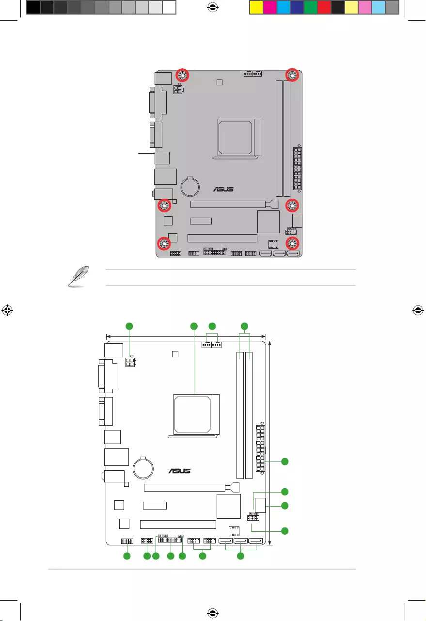
1.2.2 Screw holes
Place six screws into the holes indicated by circles to secure the motherboard to the chassis.
Donotovertightenthescrews!Doingsocandamagethemotherboard.
E9808_A68HM Series_Manual.indb 1 2014/10/16 10:08:58
1-2
Chapter 1: Product introduction
A68HM-E
Place this side towards
the rear of the chassis
1.2.3 Motherboard layout
A68HM-E
PCIEX16
PCIEX1_1
PCI1 F_PANEL
SPEAKER
COM
CLRTC
USB56 USB34
AAFP
SPDIF_OUT
ATX12V
EATXPWR
CPU_FAN CHA_FAN
BATTERY
Super
I/O
ALC
887
8111
GR
22.6cm(8.9in)
AMD®
A68H
DDR3 DIMM_A1 (64bit, 240-pin module)
DDR3 DIMM_B1 (64bit, 240-pin module)
SATA6G_1 SATA6G_2 SATA6G_3
SATA6G_4
AUDIO
KBMS
LAN_USB12
USB1112
18.0cm(7.0in)
SOCKET FM2+
DIGI
+VRM
64Mb
BIOS
DVI
VGA
TPM
21 43
6
1
5
7
8910111213 6
ThelayoutillustrationsinthisusermanualareforA68HM-Eonly.
E9808_A68HM Series_Manual.indb 2 2014/10/16 10:08:58
1-3
Connectors/Jumpers/Slots/LED Page
1. ATXpowerconnectors(24-pinEATXPWR,4-pinATX12V) 1-14
2. AMDFM2+socket 1-3
3. CPUandchassisfanconnectors(4-pinCPU_FANand4-pinCHA_FAN) 1-13
4. DDR3DIMMslots 1-6
5. Speakerconnector(4-pinSPEAKER) 1-17
6. SATA6.0Gb/sconnectors(7-pinSATA6G_1~4) 1-15
7. Systempanelconnector(10-1pinF_PANEL) 1-16
8. USB2.0connectors(10-1pinUSB34,USB56) 1-18
9. ClearRTCRAM(2-pinCLRTC) 1-10
10. TPMconnector(20-1pinTPM) 1-13
11. Digitalaudioconnector(4-1pinSPDIF_OUT) 1-15
12. Serialportconnector(10-1pinCOM) 1-18
13. Frontpanelaudioconnector(10-1pinAAFP) 1-17
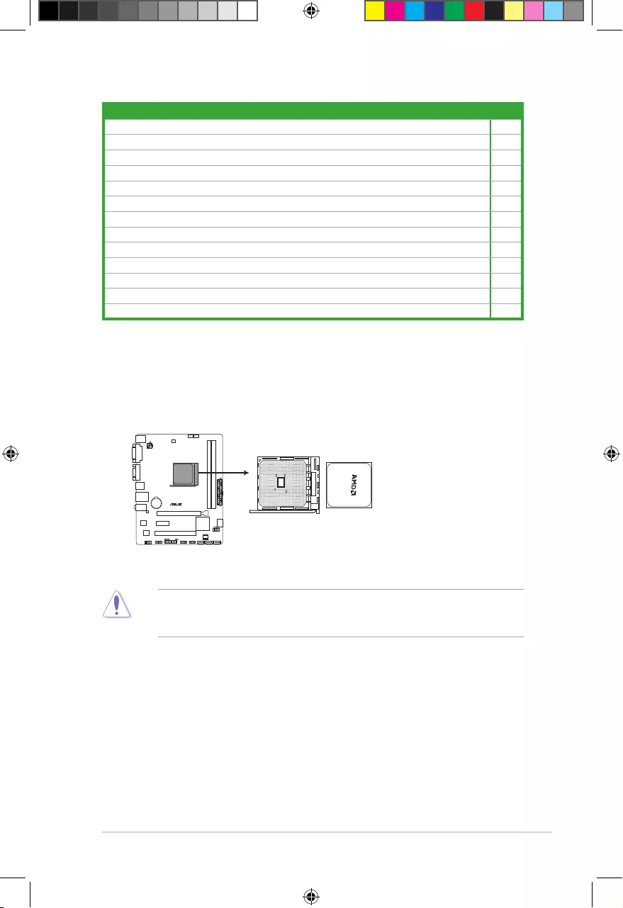
EnsurethatyouuseanAPUdesignedfortheFM2+socket.TheAPUtsinonlyone
correctorientation.DONOTforcetheAPUintothesockettopreventbendingthepinsand
damagingtheAPU!
1.3 Accelerated Processing Unit (APU)
ThismotherboardcomeswithanFM2+socketdesignedforAMD®A-series/Athlon™Series
graphics.
A68HM-E
A68HM-E CPU socket FM2+
E9808_A68HM Series_Manual.indb 3 2014/10/16 10:08:58
1-4
Chapter 1: Product introduction
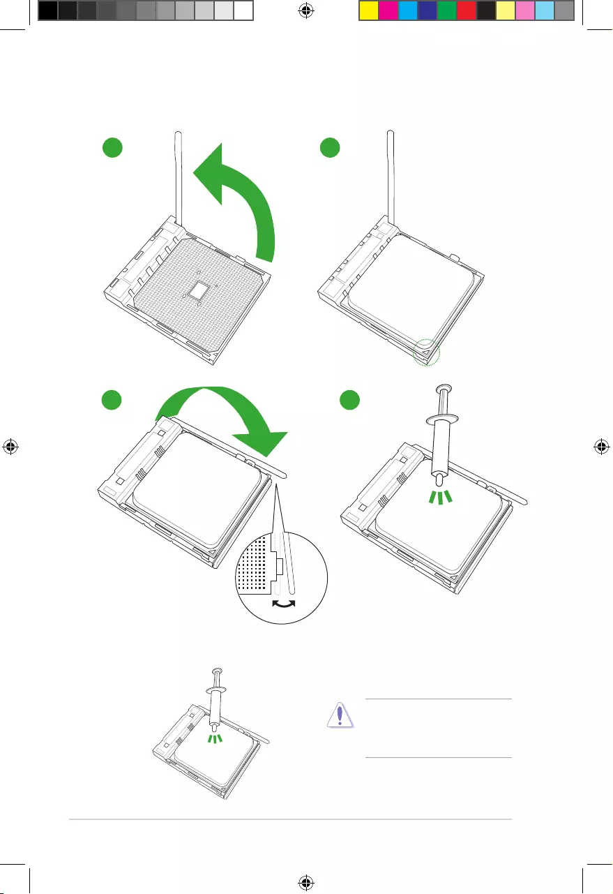
1.3.1 Installing the APU
1 2
43
1.3.2 APU heatsink and fan assembly installation
ApplytheThermalInterfaceMaterial
totheAPUheatsinkandAPUbefore
you install the heatsink and fan if
necessary.
E9808_A68HM Series_Manual.indb 4 2014/10/16 10:09:00
1-5
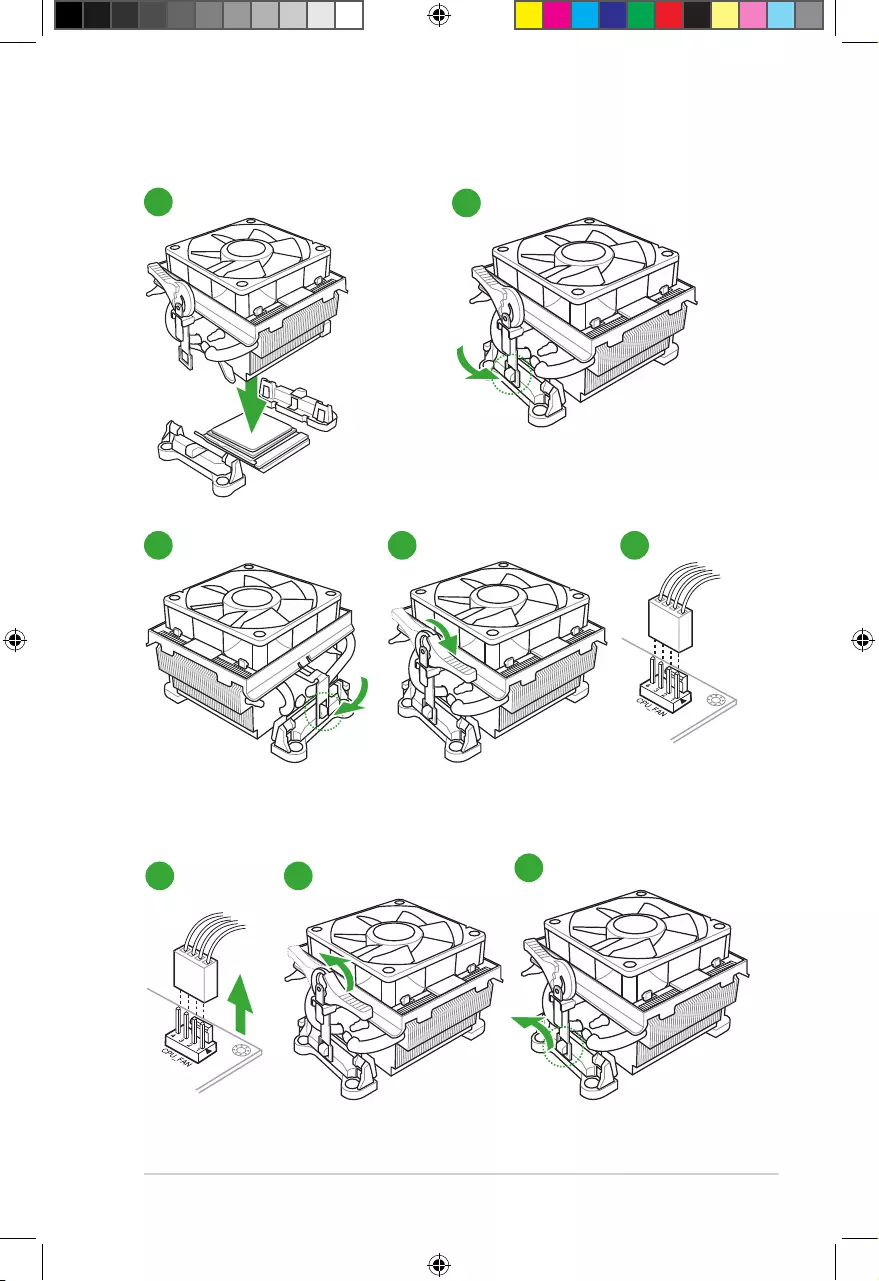
12
To install the APU heatsink and fan assembly
53 4
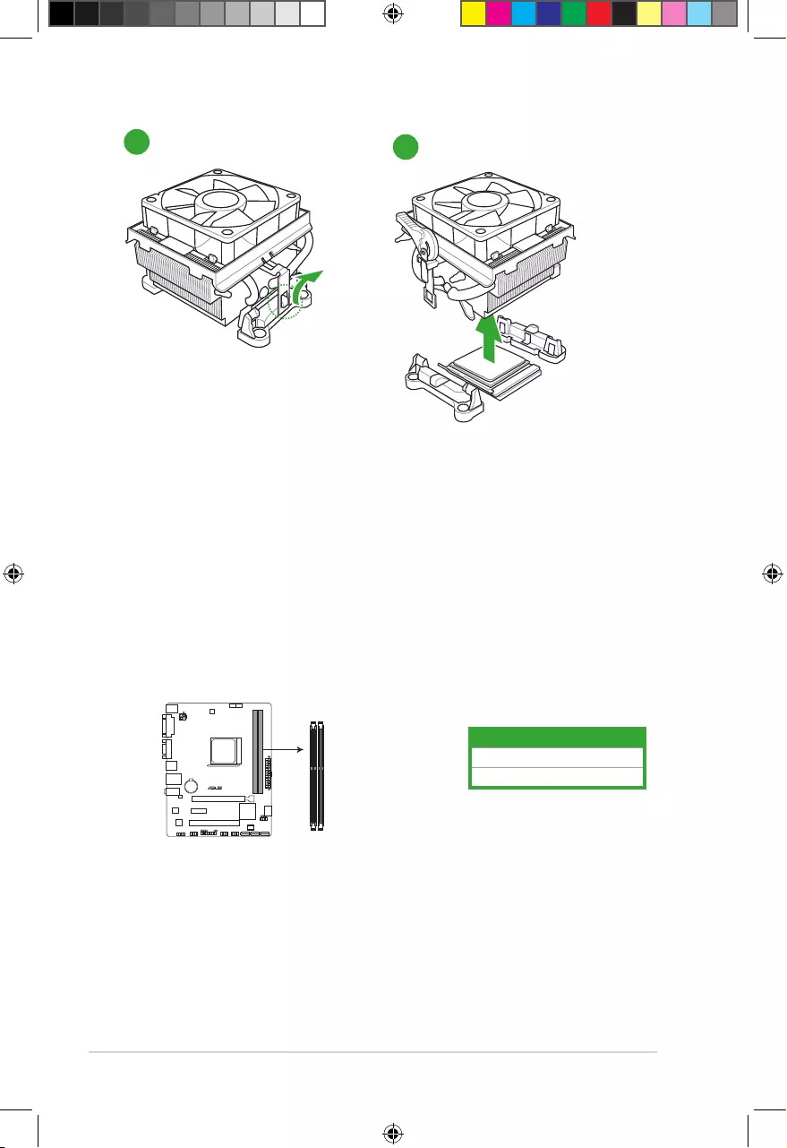
To uninstall the APU heatsink and fan assembly
1 2 3
E9808_A68HM Series_Manual.indb 5 2014/10/16 10:09:01
1-6
Chapter 1: Product introduction
5
4
1.4 System memory
1.4.1 Overview
ThemotherboardcomeswithtwoDoubleDataRate3(DDR3)DualInlineMemoryModules
(DIMM)sockets.
ADDR3modulehasthesamephysicaldimensionsasaDDR2DIMMbutisnotched
differentlytopreventinstallationonaDDR2DIMMsocket.DDR3modulesaredevelopedfor
better performance with less power consumption.
ThegureillustratesthelocationoftheDDR3DIMMsockets:
Channel Sockets
ChannelA DIMM_A1
ChannelB DIMM_B1
A68HM-E
A68HM-E 240-pin DDR3 DIMM sockets
DIMM_A1
DIMM_B1
E9808_A68HM Series_Manual.indb 6 2014/10/16 10:09:02
1-7
1.4.2 Memory configurations
Youmayinstall1GB,2GB,4GB,and8GBunbufferednon-ECCDDR3DIMMsintotheDIMM
sockets.
• YoumayinstallvaryingmemorysizesinChannelAandChannelB.Thesystemmaps
thetotalsizeofthelower-sizedchannelforthedual-channelconguration.Anyexcess
memoryfromthehigher-sizedchannelisthenmappedforsingle-channeloperation.
• AlwaysinstallDIMMswiththesameCASlatency.Foroptimalcompatibility,we
recommendthatyouinstallmemorymodulesofthesameversionordatecode(D/C)
fromthesamevendor.Checkwiththeretailertogetthecorrectmemorymodules.
• Duetothememoryaddresslimitationon32-bitWindows®OS,whenyouinstall4GB
ormorememoryonthemotherboard,theactualusablememoryfortheOScanbe
about3GBorless.Foreffectiveuseofmemory,werecommendthatyoudoanyofthe
following:
- Installamaximumof3GBsystemmemoryifyouareusinga32-bitWindows®
OS.
- Usea64-bitWindows®OSifyouwanttoinstall4GBormorememoryonthe
motherboard.
• ThismotherboarddoesnotsupportDIMMsmadeupof512Mb(64MB)chipsorless.
• Themaximum32GBmemorycapacitycanbesupportedwith16GBoraboveDIMMs.
ASUSwillupdatethememoryQVLoncetheDIMMsareavailableinthemarket.
• ThedefaultmemoryoperationfrequencyisdependentonitsSerialPresenceDetect
(SPD),whichisthestandardwayofaccessinginformationfromamemorymodule.
Underthedefaultstate,somememorymodulesforoverclockingmayoperateata
lowerfrequencythanthevendor-markedvalue.Tooperateatthevendor-marked
oratahigherfrequency,refertosection2.5 Ai Tweaker menu for manual memory
frequencyadjustment.
• Forsystemstability,useamoreefcientmemorycoolingsystemtosupportafull
memoryload(2DIMMs)oroverclockingcondition.
• Refertowww.asus.comforthelatestMemoryQVL(QualiedVendorsList).
E9808_A68HM Series_Manual.indb 7 2014/10/16 10:09:02
1-8
Chapter 1: Product introduction
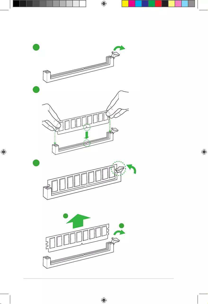
1.4.3 Installing a DIMM
1
2
3
To remove a DIMM
B
A
E9808_A68HM Series_Manual.indb 8 2014/10/16 10:09:02
1-9
1.5 Expansion slots
Inthefuture,youmayneedtoinstallexpansioncards.Thefollowingsub-sectionsdescribe
the slots and the expansion cards that they support.
Unplugthepowercordbeforeaddingorremovingexpansioncards.Failuretodosomay
cause you physical injury and damage motherboard components.
1.5.1 Installing an expansion card
Toinstallanexpansioncard:
1. Beforeinstallingtheexpansioncard,readthedocumentationthatcamewithitand
make the necessary hardware settings for the card.
2. Removethesystemunitcover(ifyourmotherboardisalreadyinstalledinachassis).
3. Removethebracketoppositetheslotthatyouintendtouse.Keepthescrewforlater
use.
4. Alignthecardconnectorwiththeslotandpressrmlyuntilthecardiscompletely
seated on the slot.
5. Securethecardtothechassiswiththescrewyouremovedearlier.
6. Replacethesystemcover.
1.5.2 Configuring an expansion card
Afterinstallingtheexpansioncard,congureitbyadjustingthesoftwaresettings.
1. TurnonthesystemandchangethenecessaryBIOSsettings,ifany.SeeChapter2for
informationonBIOSsetup.
2. AssignanIRQtothecard.
3. Installthesoftwaredriversfortheexpansioncard.
WhenusingPCIcardsonsharedslots,ensurethatthedriverssupport“ShareIRQ”orthat
thecardsdonotneedIRQassignments.Otherwise,conictswillarisebetweenthetwoPCI
groups,makingthesystemunstableandthecardinoperable.
1.5.3 PCI slot
ThePCIslotsupportscardssuchasaLANcard,SCSIcard,USBcard,andothercardsthat
complywithPCIspecications.
E9808_A68HM Series_Manual.indb 9 2014/10/16 10:09:02
1-10
Chapter 1: Product introduction
1.5.4 PCI Express x1 slot
ThismotherboardsupportsPCIExpress2.0x1networkcards,SCSIcards,andothercards
thatcomplywiththePCIExpressspecications.
1.5.5 PCI Express x16 slot
ThismotherboardsupportsonePCIExpress3.0/2.0x16graphicscardsthatcomplywiththe
PCIExpressspecications.
IRQ assignments for this motherboard
A B C D E F G H
PCIEx16_1 – – shared – – – – –
PCIEx1_1 shared – – – – – – –
PCI1slot – – – – shared – – –
RealtekLANcontroller – – shared – — – – –
HDaudio shared – – – – – – –
SATAcontroller – – – shared – – – –
OnChipUSBEHCI1/2/3 – shared – – – – – –
OnChipUSBOHCI1/2/3/4 – – shared – – – – –
OnChipXHCIcontroller – – shared – – – – –
1.6 Headers
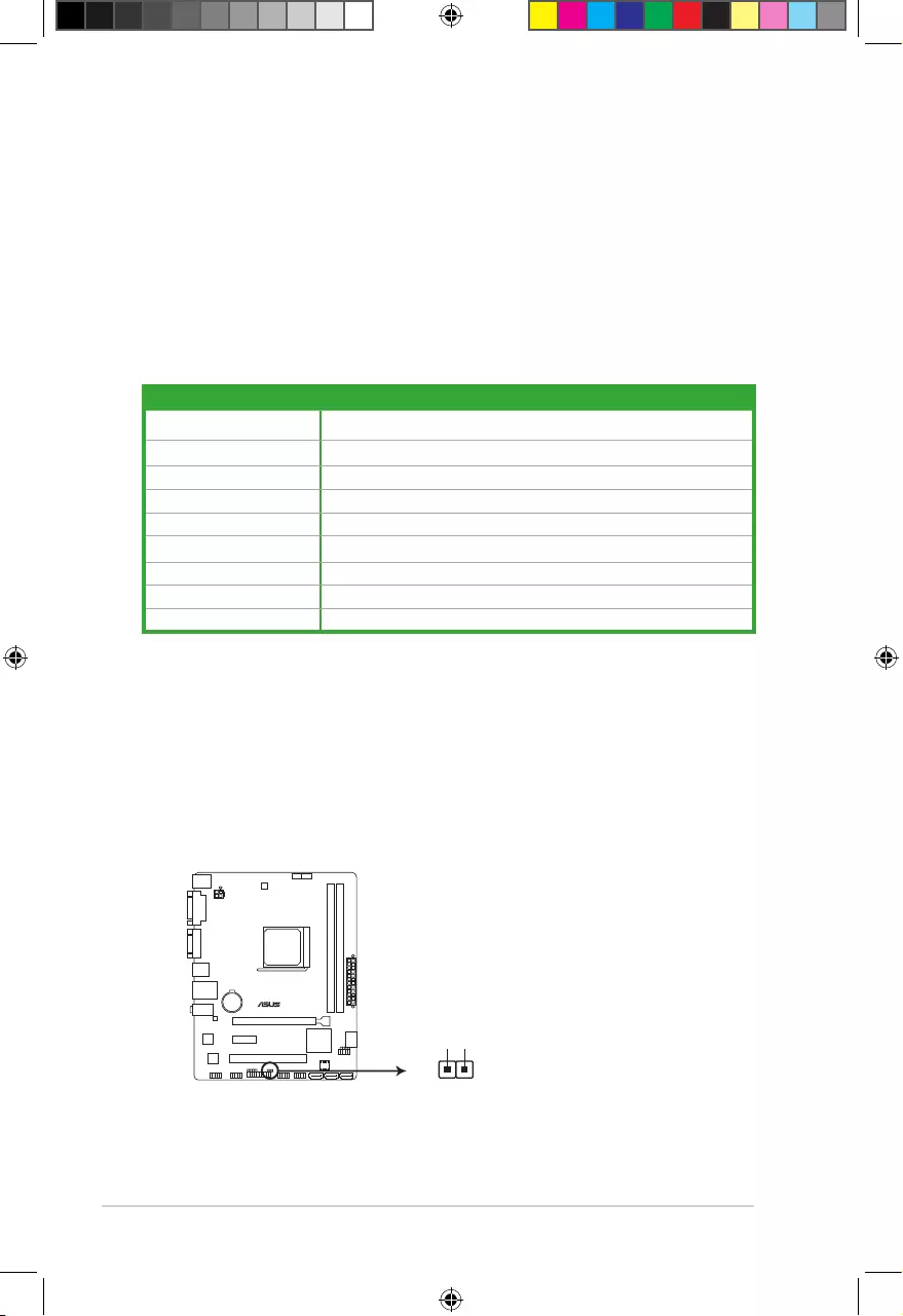
Clear RTC RAM (2-pin CLRTC)
ThisheaderallowsyoutocleartheRealTimeClock(RTC)RAMinCMOS.Youcan
cleartheCMOSmemoryofdate,time,andsystemsetupparametersbyerasingthe
CMOSRTCRAMdata.TheonboardbuttoncellbatterypowerstheRAMdatain
CMOS,whichincludesystemsetupinformationsuchassystempasswords.
A68HM-E
A68HM-E Clear RTC RAM
CLRTC
+3V_BAT
GND
PIN 1
E9808_A68HM Series_Manual.indb 10 2014/10/16 10:09:02
1-11
ToerasetheRTCRAM:
1. TurnOFFthecomputerandunplugthepowercord.
2. Useametalobjectsuchasascrewdrivertoshortthetwopins.
3. PlugthepowercordandturnONthecomputer.
4. Holddownthe<Del>keyduringthebootprocessandenterBIOSsetuptore-
enter data.
• Ifthestepsabovedonothelp,removetheonboardbatteryandshortthetwopins
againtocleartheCMOSRTCRAMdata.AfterclearingtheCMOS,reinstallthe
battery.
• YoudonotneedtocleartheRTCwhenthesystemhangsduetooverclocking.For
systemfailureduetooverclocking,usetheCPUParameterRecall(C.P.R.)feature.
Shutdownandrebootthesystem,thentheBIOSautomaticallyresetsparameter
settingstodefaultvalues.
1.7 Connectors
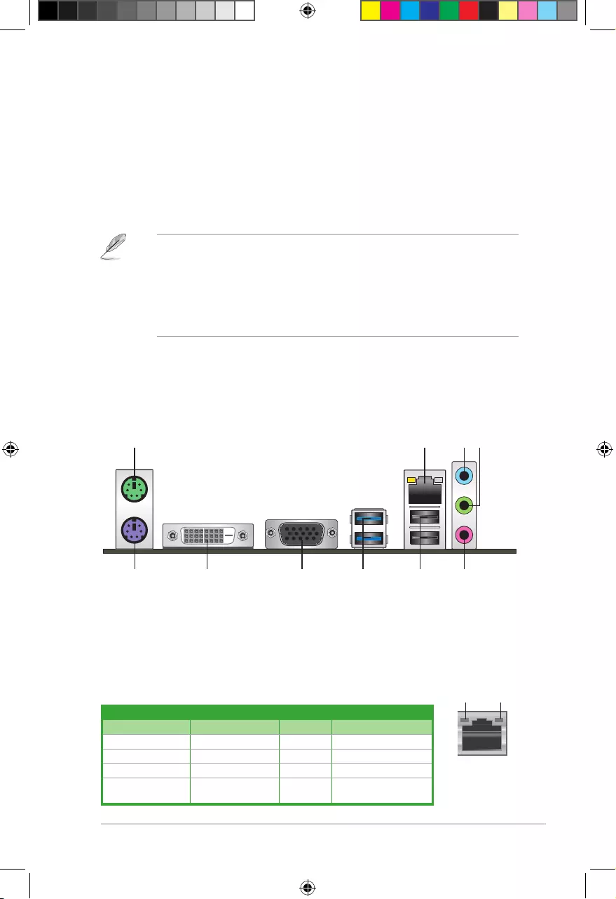
1.7.1 Rear panel connectors
1. PS/2 Mouse port (green).ThisportisforaPS/2mouse.
2. LAN (RJ-45) port.ThisportallowsGigabitconnectiontoaLocalAreaNetwork(LAN)
through a network hub.
3 42
57 6
1
10 89
LAN port
SPEED
LED
ACT/LINK
LED
Activity/Link LED Speed LED
Status Description Status Description
Off Nolink OFF 10Mbpsconnection
Orange Linked ORANGE 100Mbpsconnection
Orange(Blinking) Dataactivity GREEN 1Gbpsconnection
Orange(Blinking
thensteady)
Readytowakeup
from S5 mode
LAN port LED indications
E9808_A68HM Series_Manual.indb 11 2014/10/16 10:09:03
1-12
Chapter 1: Product introduction
3. Line In port (light blue).Thisportconnectstothetape,CD,DVDplayer,orother
audio sources.
4. Line Out port (lime). Thisportconnectstoaheadphoneoraspeaker.Inthe4.1,5.1,
and7.1-channelcongurations,thefunctionofthisportbecomesFrontSpeakerOut.
5. Microphone port (pink). This port connects to a microphone.
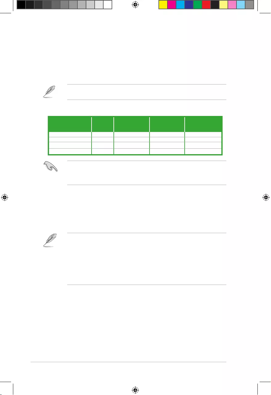
Refertotheaudiocongurationtablebelowforthefunctionoftheaudioportsin2.1,4.1,
5.1,or7.1-channelconguration.
Audio 2.1, 4.1, 5.1, or 7.1-channel configuration
Port
Headset
2.1-
channel
4.1-channel 5.1-channel 7.1-channel
LightBlue(Rearpanel) LineIn RearSpeakerOut RearSpeakerOut RearSpeakerOut
Lime(Rearpanel) LineOut FrontSpeakerOut FrontSpeakerOut FrontSpeakerOut
Pink(Rearpanel) MicIn MicIn Bass/Center Bass/Center
Lime(Frontpanel) — — — SideSpeakerOut
To configure a 7.1-channel audio output:
UseachassiswithHDaudiomoduleinthefrontpaneltosupporta7.1-channelaudio
output.
6. USB 2.0 ports 1 and 2.Thesetwo4-pinUniversalSerialBus(USB)portsareforUSB
2.0/1.1devices.
7. USB 3.0 ports 1 and 2.Thesetwo9-pinUniversalSerialBus(USB)portsconnectto
USB3.0/2.0devices.
• DuetoUSB3.0controllerlimitations,USB3.0devicescanonlybeusedundera
Windows®OSenvironmentandafterUSB3.0driverinstallation.
• ThepluggedUSB3.0devicemayrunonxHCIorEHCImode,dependingonthe
operating system’s setting.
• USB3.0devicescanonlybeusedfordatastorage.
• WestronglyrecommendthatyouconnectUSB3.0devicestoUSB3.0portsforfaster
andbetterperformancefromyourUSB3.0devices.
8. Video Graphics Adapter (VGA) port. This15-pinportisforaVGAmonitororother
VGA-compatibledevices.
9. DVI-D port. ThisportisforanyDVI-Dcompatibledevice.DVI-Dcan’tbeconvertedto
outputRGBSignaltoCRTandisn’tcompatiblewithDVI-I.
10. PS/2 Keyboard port (purple).ThisportisforaPS/2keyboard.
E9808_A68HM Series_Manual.indb 12 2014/10/16 10:09:03
1-13
DONOTforgettoconnectthefancablestothefanconnectors.Insufcientairowinside
thesystemmaydamagethemotherboardcomponents.Thesearenotjumpers!DONOT
place jumper caps on the fan connectors.
• TheCPU_FANconnectorsupportsaCPUfanofmaximum2A(24W)fanpower.
• TheCPU_FANandCHA_FANconnectorssupporttheASUSFanXpertfeature.
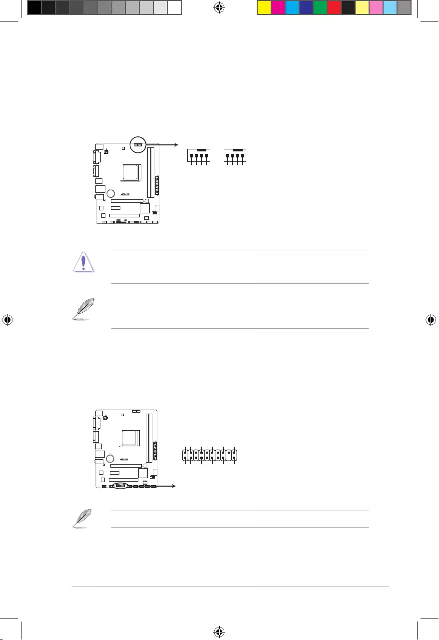
1.7.2 Internal connectors
1. CPU and chassis fan connectors (4-pin CPU_FAN, and 4-pin CHA_FAN)
Connectthefancablestothefanconnectorsonthemotherboard,ensuringthatthe
black wire of each cable matches the ground pin of the connector.
A68HM-E
A68HM-E Fan connectors
CPU_FAN
CPU FAN PWM
CPU FAN IN
CPU FAN PWR
GND
CHA_FAN
CHA FAN PWM
CHA FAN IN
CHA FAN PWR
GND
2. TPM connector (20-1 pin TPM)
ThisconnectorsupportsaTrustedPlatformModule(TPM)system,whichcansecurely
storekeys,digitalcerticates,passwords,anddata.ATPMsystemalsohelpsenhance
networksecurity,protectsdigitalidentities,andensuresplatformintegrity.
A68HM-E
A68HM-E TPM connector
PIN 1
TPM
PWRDWN
GND
+3VSB
NC
LAD0
+3V
LAD3
PCIRST#
FRAME
PCICLK
NC
CLKRUN
SERIRQ
NC
GND
LAD1
LAD2
NC
GND
TheTPMmoduleispurchasedseparately.
E9808_A68HM Series_Manual.indb 13 2014/10/16 10:09:04
1-14
Chapter 1: Product introduction
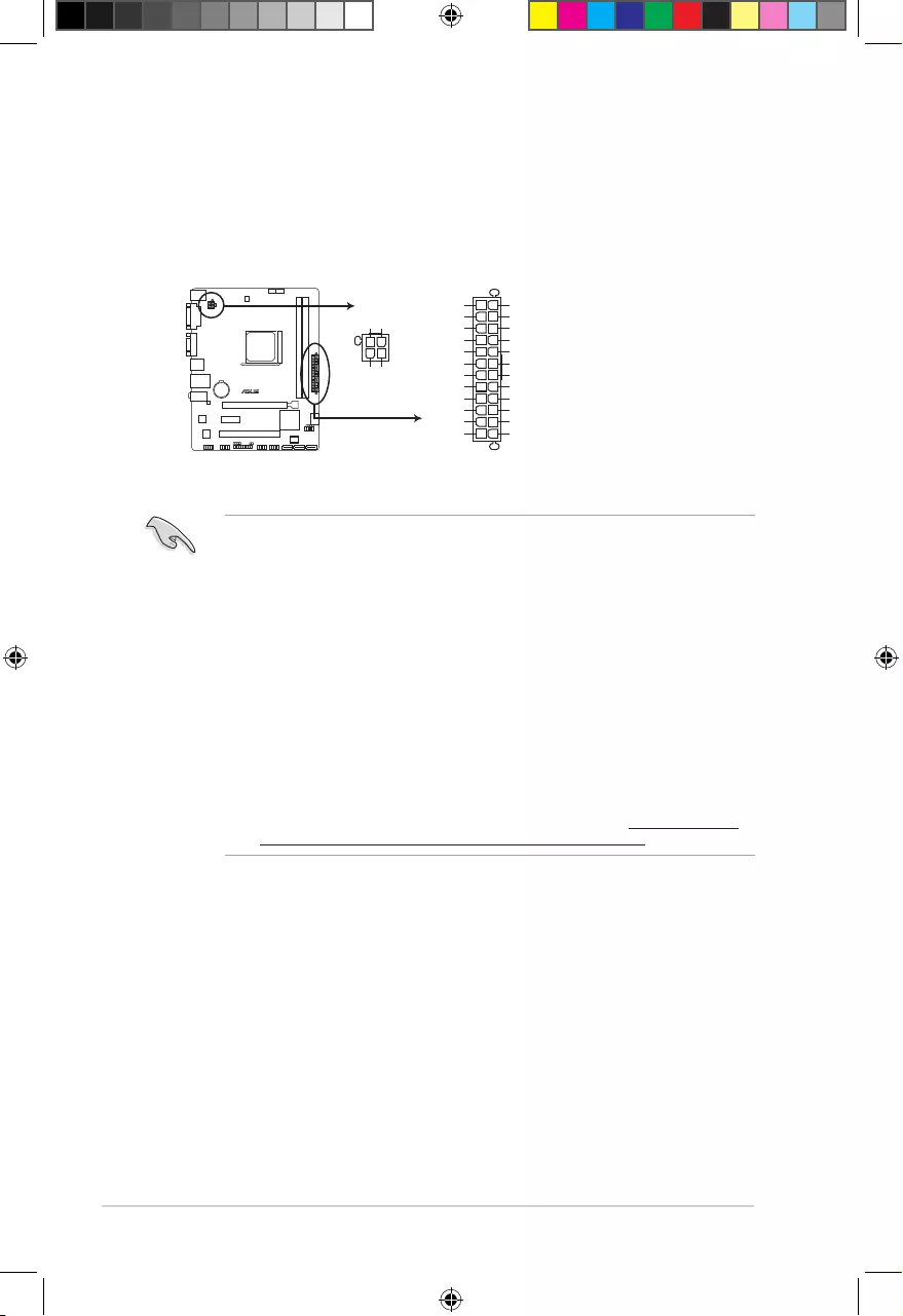
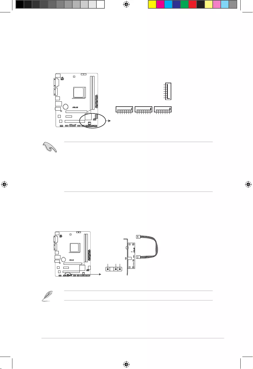
3. ATX power connectors (24-pin EATXPWR, 4-pin ATX12V)
TheseconnectorsareforanATXpowersupply.Theplugsfromthepowersupplyare
designedtottheseconnectorsinonlyoneorientation.Findtheproperorientationand
pushdownrmlyuntiltheconnectorscompletelyt.
•
WerecommendthatyouuseanATX12VSpecication2.0-compliantpowersupply
unit(PSU)withaminimumof300Wpowerrating.ThisPSUtypehas24-pinand4-pin
power plugs.
•
IfyouintendtouseaPSUwith20-pinand4-pinpowerplugs,ensurethatthe20-pin
powerplugcanprovideatleast15Aon+12VandthatthePSUhasaminimumpower
ratingof300W.Thesystemmaybecomeunstableormaynotbootupifthepoweris
inadequate.
•
DONOTforgettoconnectthe4-pinATX+12Vpowerplug.Otherwise,thesystemwill
not boot up.
• WerecommendthatyouuseaPSUwithhigherpoweroutputwhenconguringa
systemwithmorepower-consumingdevicesorwhenyouintendtoinstalladditional
devices.Thesystemmaybecomeunstableormaynotbootupifthepoweris
inadequate.
•
Ifyouareuncertainabouttheminimumpowersupplyrequirementforyoursystem,
refertotheRecommendedPowerSupplyWattageCalculatorathttp://support.asus.
com/PowerSupplyCalculator/PSCalculator.aspx?SLanguage=en-us for details.
A68HM-E
A68HM-E ATX power connectors
EATXPWR
PIN 1
GND
+5 Volts
+5 Volts
+5 Volts
-5 Volts
GND
GND
GND
PSON#
GND
-12 Volts
+3 Volts
+3 Volts
+12 Volts
+12 Volts
+5V Standby
Power OK
GND
+5 Volts
GND
+5 Volts
GND
+3 Volts
+3 Volts
ATX12V
PIN 1
+12V DC
+12V DC
GND
GND
E9808_A68HM Series_Manual.indb 14 2014/10/16 10:09:04
1-15
4. Serial ATA 6.0 Gb/s connectors (7-pin SATA6G 1~4)
TheseconnectorsarefortheSerialATA6.0Gb/ssignalcablesforSerialATAhard
diskdrivesandopticaldiscdrives.IfyouinstalledSerialATAharddiskdrives,youcan
createaRAID0,RAID1,orRAID10congurationthroughtheonboardcontroller.
• TheseconnectorsaresettoAHCImodebydefault.IfyouintendtocreateaSerialATA
RAIDsetusingtheseconnectors,setthetypeoftheSATAconnectorsintheBIOSto
[RAID].
• YoumustinstallWindows®XPServicePack3orlaterversionbeforeusingSerial
ATAharddiskdrives.TheSerialATARAIDfeatureisavailableonlyifyouareusing
Windows®XPSP3orlaterversion.
• Whenusinghot-plugandNCQ,setthetypeoftheSATAconnectorsintheBIOSto
[AHCI].
SATA6G_2
GND
RSATA_TXP1
RSATA_TXN1
GND
RSATA_RXN1
RSATA_RXP1
GND
SATA6G_1
GND
RSATA_TXP2
RSATA_TXN2
GND
RSATA_RXN2
RSATA_RXP2
GND
SATA6G_3
GND
RSATA_TXP3
RSATA_TXN3
GND
RSATA_RXN3
RSATA_RXP3
GND
GND
RSATA_TXP4
RSATA_TXN4
GND
RSATA_RXN4
RSATA_RXP4
GND
SATA6G_4
A68HM-E
A68HM-E SATA 6.0Gb/s connectors
5. Digital audio connector (4-1 pin SPDIF_OUT)
ThisconnectorisforanadditionalSony/PhilipsDigitalInterface(S/PDIF)port.
SPDIF_OUT
+5V
SPDIFOUT
GND
A68HM-E
A68HM-E Digital audio connector
TheS/PDIFmoduleispurchasedseparately.
E9808_A68HM Series_Manual.indb 15 2014/10/16 10:09:04
1-16
Chapter 1: Product introduction
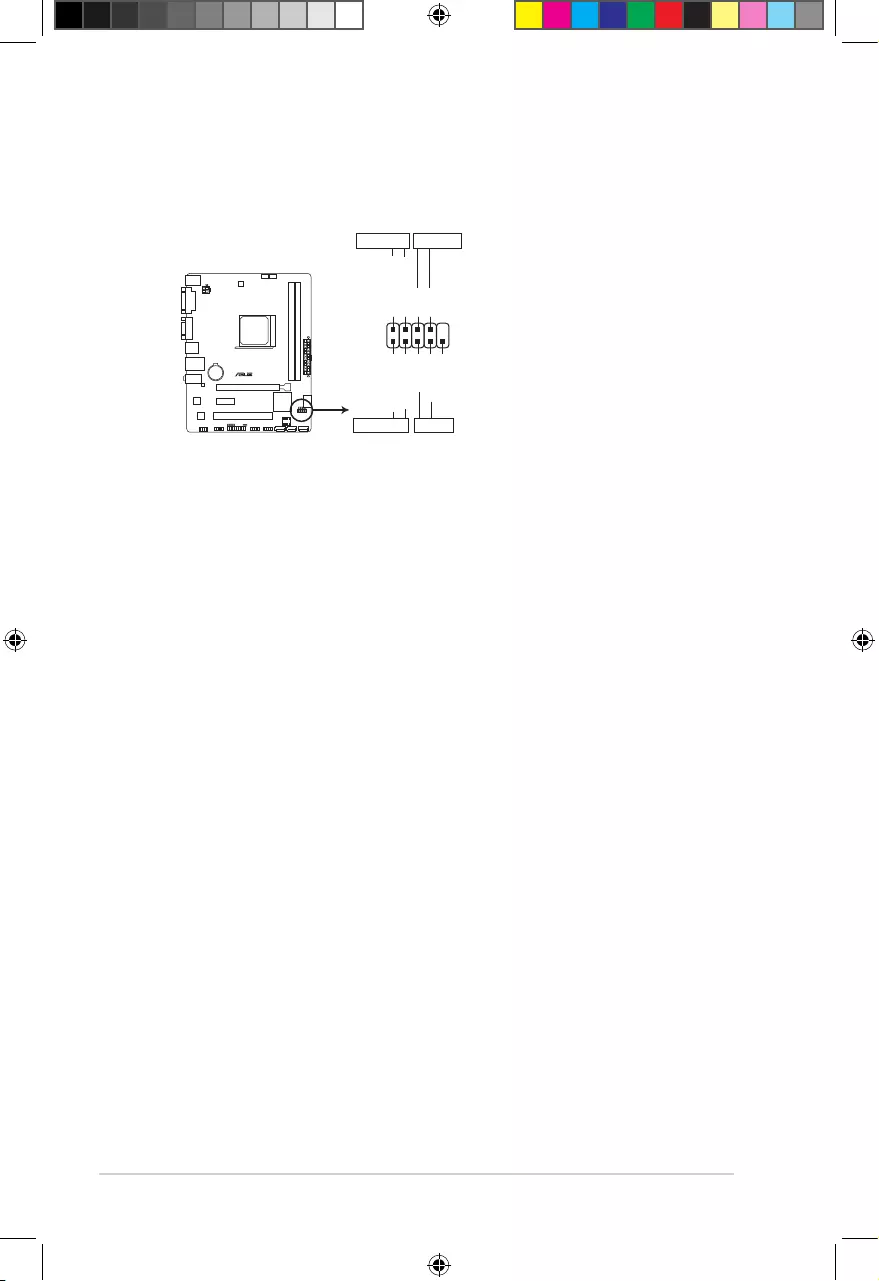
6. System panel connector (10-1 pin PANEL)
Thisconnectorsupportsseveralchassis-mountedfunctions.
• SystempowerLED(2-pinPWR_LED)
This2-pinconnectorisforthesystempowerLED.ConnectthechassispowerLED
cabletothisconnector.ThesystempowerLEDlightsupwhenyouturnonthesystem
power,andblinkswhenthesystemisinsleepmode.
•
Hard disk drive activity LED (2-pin HDD_LED)
This2-pinconnectorisfortheHDDActivityLED.ConnecttheHDDActivityLEDcable
tothisconnector.TheHDDLEDlightsuporasheswhendataisreadfromorwritten
totheHDD.
•
ATX power button/soft-off button (2-pin PWR_BTN)
This 2-pin connector is for the system power button.
•
Reset button (2-pin RESET)
This 2-pin connector is for the chassis-mounted reset button for system reboot without
turning off the system power.
A68HM-E
PIN 1
PWR BTN
PWR_LED+
PWR_LED-
PWR
GND
HDD_LED+
HDD_LED-
Ground
HWRST#
(NC)
F_PANEL
+PWR LED-
+HDD_LED- RESET
A68HM-E System panel connector
E9808_A68HM Series_Manual.indb 16 2014/10/16 10:09:04
1-17
7. Front panel audio connector (10-1 pin AAFP)
Thisconnectorisforachassis-mountedfrontpanelaudioI/Omodulethatsupports
eitherHighDenitionAudioorAC`97audiostandard.Connectoneendofthefront
panelaudioI/Omodulecabletothisconnector.
• Werecommendthatyouconnectahigh-denitionfrontpanelaudiomoduletothis
connectortoavailofthemotherboardhigh-denitionaudiocapability.
• Ifyouwanttoconnectahighdenitionfrontpanelaudiomoduletothisconnector,set
the Front Panel TypeitemintheBIOSto[HD].
• ThefrontpanelaudioI/Omoduleispurchasedseparately.
A68HM-E
A68HM-E Speaker Out connector
+5V
GND
GND
Speaker Out
SPEAKER
PIN 1
A68HM-E
A68HM-E Front panel audio connector
AAFP
PIN 1
AGND
NC
SENSE1_RETUR
SENSE2_RETUR
PORT1 L
PORT1 R
PORT2 R
SENSE_SEND
PORT2 L
HD-audio-compliant
pin definition
PIN 1
AGND
NC
NC
NC
MIC2
MICPWR
Line out_R
NC
Line out_L
Legacy AC’97
compliant definition
8. Speaker connector (4-pin SPEAKER)
The4-pinconnectorisforthechassis-mountedsystemwarningspeaker.Thespeaker
allows you to hear system beeps and warnings.
E9808_A68HM Series_Manual.indb 17 2014/10/16 10:09:05
1-18
Chapter 1: Product introduction
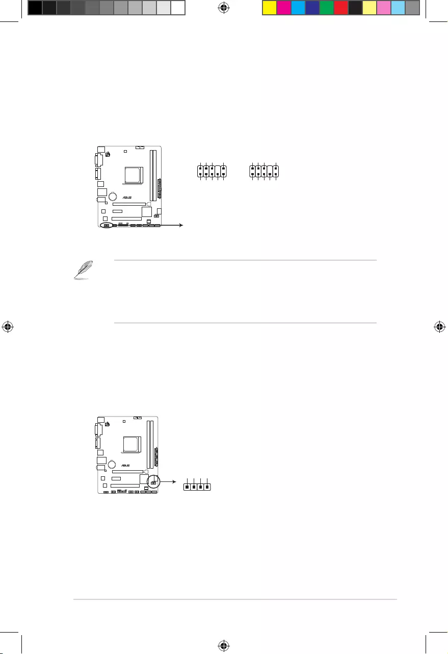
9. USB 2.0 connectors (10-1 pin USB34, USB56)
TheseconnectorsareforUSB2.0ports.ConnecttheUSBmodulecabletoanyof
theseconnectors,theninstallthemoduletoaslotopeningatthebackofthesystem
chassis.TheseUSBconnectorscomplywithUSB2.0specicationthatsupportsupto
480Mbpsconnectionspeed.
Neverconnecta1394cabletotheUSBconnectors.Doingsowilldamagethe
motherboard!
TheUSB2.0moduleispurchasedseparately.
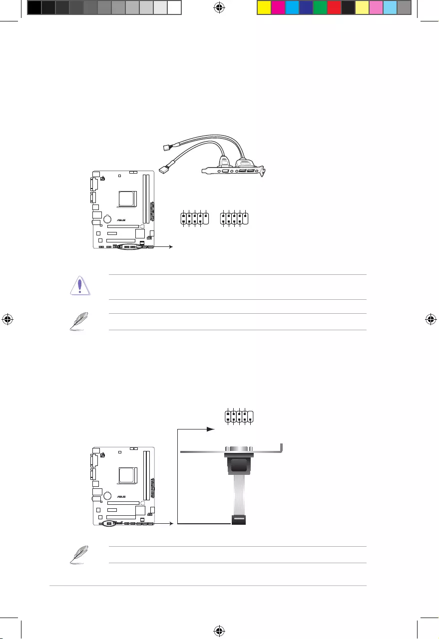
10. Serial port connector (10-1 pin COM)
Thisconnectorisforaserial(COM)port.Connecttheserialportmodulecabletothis
connector,theninstallthemoduletoaslotopeningatthebackofthesystemchassis.
TheCOMmoduleispurchasedseparately.
A68HM-E
A68HM-E USB2.0 connectors
PIN 1
USB+5V
USB_P5-
USB_P5+
GND
NC
USB+5V
USB_P6-
USB_P6+
GND
USB56 USB34
PIN 1
USB+5V
USB_P3-
USB_P3+
GND
NC
USB+5V
USB_P4-
USB_P4+
GND
A68HM-E
A68HM-E Serial port connectors
PIN 1
COM
DCD
TXD
GND
RTS
RI
RXD
DTR
DSR
CTS
E9808_A68HM Series_Manual.indb 18 2014/10/16 10:09:05
1-19
1.8 Software support
1.8.1 Installing an operating system
ThismotherboardsupportsWindows®8.1(32bit/64bit)/Windows®8(32bit/64bit)/Windows®
7(32bit/64bit)/Windows®XPOperatingSystems(OS).AlwaysinstallthelatestOSversion
andcorrespondingupdatestomaximizethefeaturesofyourhardware.
• Motherboardsettingsandhardwareoptionsvary.RefertoyourOSdocumentationfor
detailed information.
• EnsurethatyouinstallWindows®XPServicePack3orlaterversionsbeforeinstalling
thedriversforbettercompatibilityandsystemstability.
1.8.2 Support DVD information
TheSupportDVDthatcomeswiththemotherboardpackagecontainsthedrivers,software
applications,andutilitiesthatyoucaninstalltoavailallmotherboardfeatures.
ThecontentsoftheSupportDVDaresubjecttochangeatanytimewithoutnotice.Visitthe
ASUSwebsiteatwww.asus.comforupdates.
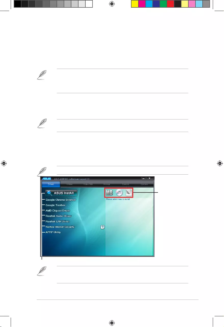
To run the Support DVD
PlacetheSupportDVDintotheopticaldrive.IfAutorunisenabledinyourcomputer,the
DVDautomaticallydisplaystheSpecialsscreenwhichcontainstheuniquefeaturesofASUS
motherboard.ClickDrivers,Utilities,MakeDisk,Manual,ContactandSpecialstabstodisplay
theirrespectivemenus.
The following screen is for reference only.
Click an item to install
Click an icon to display
Support DVD/motherboard
information
IfAutorunisNOTenabledinyourcomputer,browsethecontentsoftheSupportDVDto
locatetheleASSETUP.EXEfromtheBINfolder.Double-clicktheASSETUP.EXEtorun
theDVD.
E9808_A68HM Series_Manual.indb 19 2014/10/16 10:09:05
1-20
Chapter 1: Product introduction
E9808_A68HM Series_Manual.indb 20 2014/10/16 10:09:05
2-1
BIOS information
2
2.1 Managing and updating your BIOS
Save a copy of the original motherboard BIOS le to a USB ash disk in case you need to
restore the BIOS in the future. Copy the original motherboard BIOS using the ASUS Update
utility.
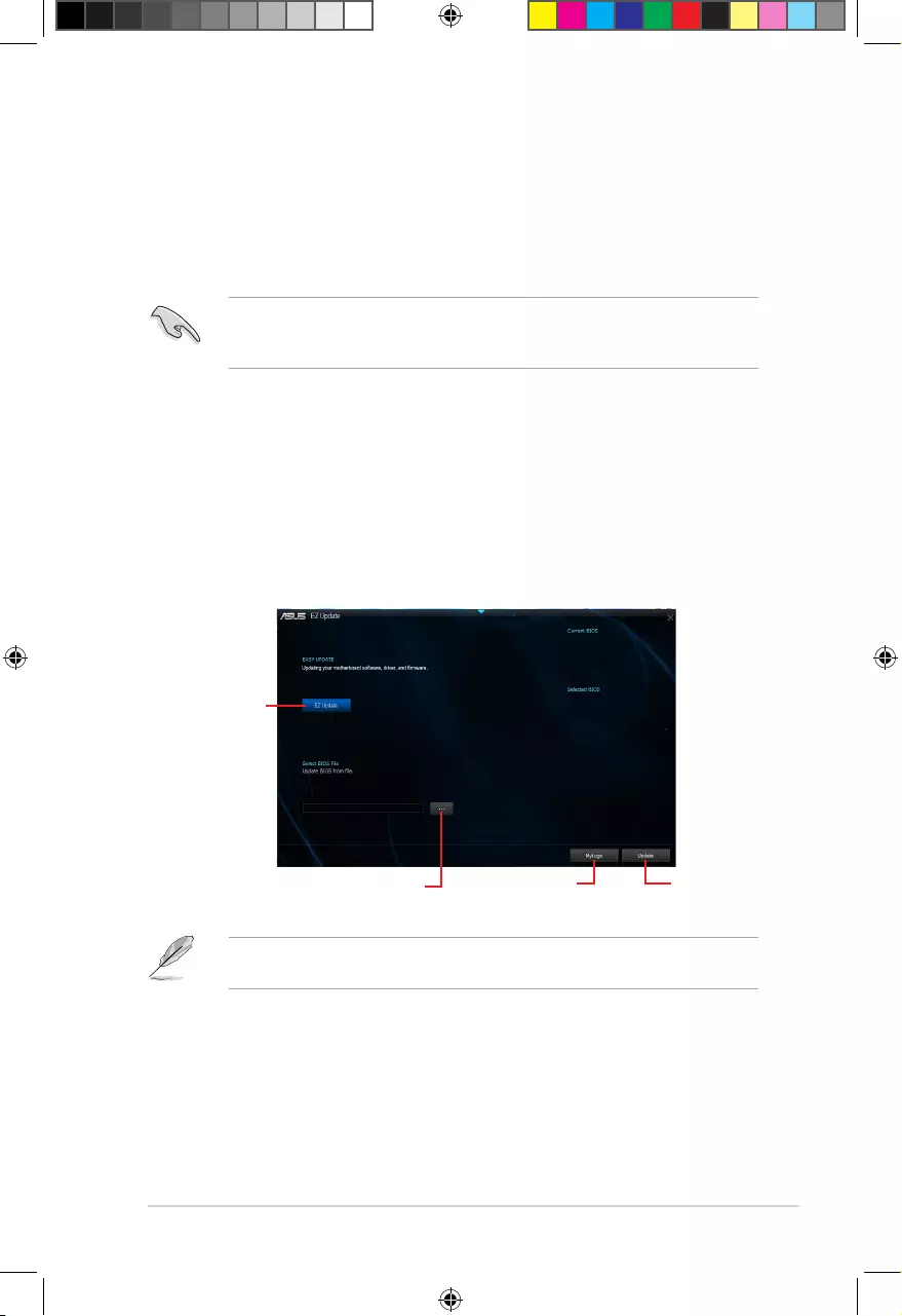
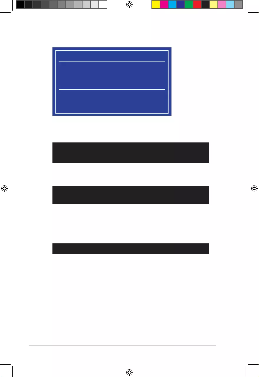
2.1.1 EZ Update
EZ Update is a utility that allows you to automatically update your motherboard’s softwares,
drivers and the BIOS version easily. With this utlity, you can also manually update the saved
BIOS and select a boot logo when the system goes into POST.
To launch EZ Update, click EZ Update on the AI Suite 3 main menu bar.
C:\Users\test\Downloads\A68HM-E-ASUS-02…
Model Name: A68HM-E
Version:0203
Release Date: 09/08/2014
File: A68HM-E-ASUS-0205.CAP
Model Name: A68HM-E
Version:0205
Release Date: 09/28/2014
Click to automatically
update your
motherboard’s
driver, software and
firmware
Click to find and
select the BIOS
from file
Click to select a
boot logo Click to update
the BIOS
EZ Update requires an Internet connection either through a network or an ISP (Internet
Service Provider).
E9808_A68HM Series_Manual.indb 1 2014/10/16 10:09:06
2-2
Chapter 2: Getting started
2.1.2 ASUS EZ Flash 2
The ASUS EZ Flash 2 feature allows you to update the BIOS without using an OS‑based
utility.
Before you start using this utility, download the latest BIOS le from the ASUS website at
www.asus.com.
To update the BIOS using EZ Flash 2:
1. Insert the USB ash disk that contains the latest BIOS le to the USB port.
2. Enter the Advanced Mode of the BIOS setup program. Go to the Tool menu to select
ASUS EZ Flash 2 Utility and press <Enter> to enable it.
3. Press <Tab> to switch to the Drive eld.
4. Press the Up/Down arrow keys to nd the USB ash disk that contains the latest BIOS,
and then press <Enter>.
5. Press <Tab> to switch to the Folder Info eld.
6. Press the Up/Down arrow keys to nd the BIOS le, and then press <Enter> to perform
the BIOS update process. Reboot the system when the update process is done.
• This function supports USB ash disks with FAT 32/16 format and single partition only.
• DO NOT shut down or reset the system while updating the BIOS to prevent system
boot failure!
2.1.3 ASUS CrashFree BIOS 3 utility
The ASUS CrashFree BIOS 3 is an auto recovery tool that allows you to restore the BIOS le
when it fails or gets corrupted during the updating process. You can restore a corrupted BIOS
le using the motherboard support DVD or a USB ash drive that contains the updated BIOS
le.
• Before using this utility, rename the BIOS le in the removable device into
A68HME.CAP (for A68HM‑E model) or A68HMK (for A68HM‑K model).
• The BIOS le in the support DVD may not be the latest version. Download the latest
BIOS le from the ASUS website at www.asus.com.
E9808_A68HM Series_Manual.indb 2 2014/10/16 10:09:06

2‑3
Recovering the BIOS
To recover the BIOS:
1. Turn on the system.
2. Insert the support DVD to the optical drive or the USB ash drive that contains the
BIOS le to the USB port.
3. The utility automatically checks the devices for the BIOS le. When found, the utility
reads the BIOS le and enters ASUS EZ Flash 2 utility automatically.
4. The system requires you to enter BIOS Setup to recover BIOS setting. To ensure
system compatibility and stability, we recommend that you press <F5> to load default
BIOS values.
DO NOT shut down or reset the system while updating the BIOS! Doing so can cause
system boot failure!
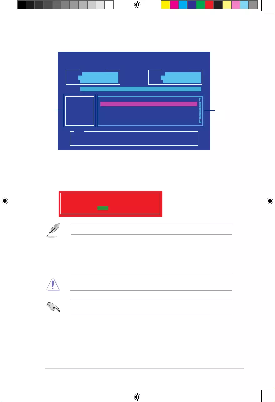
2.1.4 ASUS BIOS Updater
ASUS BIOS Updater allows you to update the BIOS in DOS environment.
The screen captures used in this section are for reference only and may not be exactly the
same as actually shown on your computer screen.
Before updating BIOS
• Prepare the motherboard support DVD and a USB ash drive.
• Download the latest BIOS le and BIOS Updater from http://support.asus.com and
save them in your USB ash drive.
NTFS is not supported under FreeDOS environment. Ensure that your USB ash drive is in
single partition and in FAT32/16 format.
• Turn off the computer.
• Ensure that your computer has a DVD optical drive.
Booting the system in DOS environment
To boot the system in DOS:
1. Insert the USB ash drive with the latest BIOS le and BIOS Updater to the USB port.
2. Boot your computer then press <F8> to launch the select boot device screen.
3. When the select boot device screen appears, insert the Support DVD into the optical
drive then select the optical drive as the boot device.
E9808_A68HM Series_Manual.indb 3 2014/10/16 10:09:06
2-4
Chapter 2: Getting started
Please select boot device:
E1: ASUS DVD-E818A6T (4069MB)
USB DISK 2.0 (3824MB)
UEFI: (FAT) USB DISK 2.0 (3824MB)
Enter Setup
and to move selection
ENTER to select boot device
ESC to boot using defaults
4. When the booting message appears, press <Enter> within ve (5) seconds to enter
FreeDOS prompt.
Updating the BIOS file
To update the BIOS le:
1. On the FreeDOS prompt, type bupdater /pc /g and press <Enter>.
2. On the BIOS Updater screen, press <Tab> to switch from Files panel to Drives panel
then select D:.
Welcome to FreeDOS (http://www.freedos.org)!
C:/> d:
D:/>
D:/> bupdater /pc /g
5. On the FreeDOS prompt, type d: then press <Enter> to switch the disk from Drive C
(optical drive) to Drive D (USB ash drive).
ISOLINUX 3.20 2006-08-26 Copyright (C) 1994-2005 H. Peter Anvin
A Bootable DVD/CD is detected. Press ENTER to boot from the DVD/CD.
If no key is pressed within 5 seconds, the system will boot next priority
device automatically. boot:
E9808_A68HM Series_Manual.indb 4 2014/10/16 10:09:06
2-5
ASUSTeK BIOS Updater for DOS V1.30 [2014/01/01]
Current ROM
BOARD: A68HM-E
VER: 0205 (H :00 B :00)
DATE: 09/28/2014
Update ROM
BOARD: Unknown
VER: Unknown
DATE: Unknown
PATH: C:\
C:
D:
FORMAN~1 <DIR>
A68HME.CAP 8390626 2014-09-12 21:14:34
Note
[Enter] Select or Load [Tab] Switch [V] Drive Info
[Up/Down/Home/End] Move [Esc] Exit
Files panel
Drives panel
3. Press <Tab> to switch from Drives panel to Files panel then press <Up/Down or Home/
End> keys to select the BIOS le and press <Enter>.
5. Select Yes then press <Enter>. When BIOS update is done, press <ESC> to exit BIOS
Updater.
6. Restart your computer.
DO NOT shut down or reset the system while updating the BIOS to prevent system boot
failure.
Ensure to load the BIOS default settings to ensure system compatibility and stability. Select
the Load Optimized Defaults item under the Exit BIOS menu.
4. After the BIOS Updater checks the selected BIOS le, select Yes to conrm the BIOS
update.
Are you sure you want to update the BIOS?
Yes No
The BIOS Backup feature is not supported due to security regulations.
E9808_A68HM Series_Manual.indb 5 2014/10/16 10:09:07
2-6
Chapter 2: Getting started
2.2 BIOS setup program
Use the BIOS Setup program to update the BIOS or congure its parameters. The BIOS
screens include navigation keys and brief online help to guide you in using the BIOS Setup
program.
Entering BIOS Setup at startup
To enter BIOS Setup at startup:
• Press <Delete> during the Power‑On Self Test (POST). If you do not press <Delete>,
POST continues with its routines.
Entering BIOS Setup after POST
To enter BIOS Setup after POST:
• Press <Ctrl>+<Alt>+<Del> simultaneously.
• Press the reset button on the system chassis.
• Press the power button to turn the system off then back on. Do this option only if you
failed to enter BIOS Setup using the rst two options.
Using the power button, reset button, or the <Ctrl>+<Alt>+<Del> keys to force reset from
a running operating system can cause damage to your data or system. We recommend to
always shut down the system properly from the operating system.
• The BIOS setup screens shown in this section are for reference purposes only, and
may not exactly match what you see on your screen.
• Visit the ASUS website at www.asus.com to download the latest BIOS le for this
motherboard.
• Ensure that a USB mouse is connected to your motherboard if you want to use the
mouse to control the BIOS setup program.
• If the system becomes unstable after changing any BIOS setting, load the default
settings to ensure system compatibility and stability. Select the Load Optimized
Defaults item under the Exit menu or press hotkey F5.
• If the system fails to boot after changing any BIOS setting, try to clear the CMOS and
reset the motherboard to the default value. See section 1.6 Headers for information
on how to erase the RTC RAM.
BIOS menu screen
The BIOS setup program can be used under two modes: EZ Mode and Advanced Mode.
You can change modes from the Exit menu or from the Exit/Advanced Mode button in the EZ
Mode/Advanced Mode screen.
E9808_A68HM Series_Manual.indb 6 2014/10/16 10:09:07
2-7
• The boot device options vary depending on the devices you installed to the system.
• The Boot Menu(F8) button is available only when the boot device is installed to the
system.
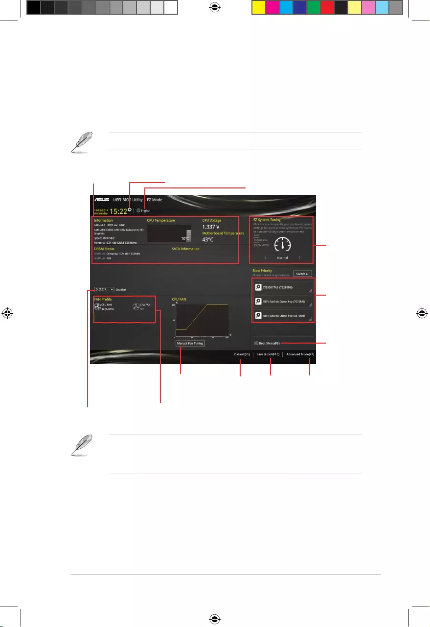
EZ Mode
By default, the EZ Mode screen appears when you enter the BIOS setup program. The EZ
Mode provides you an overview of the basic system information, and allows you to select
the display language, system performance mode and boot device priority. To access the
Advanced Mode, click Exit/Advanced Mode or press F7 for the advanced BIOS settings.
The default screen for entering the BIOS setup program can be changed.
Loads
optimized
default
Save
changes
and exit the
BIOS setup
program
Displays the system information,
CPU voltage and CPU/
motherboard temperature
Displays the A.M.P.
status
Displays the CPU/
chassis fan speed
Selects the display language
of the BIOS setup program
Sets the
system
performance
mode
Selects the
boot device
priority
Selects the
boot device
priority
Displays the
Advanced mode
menus
Sets the system date and time
Click to set
Fan Tuning
manually
E9808_A68HM Series_Manual.indb 7 2014/10/16 10:09:07
2‑8
Chapter 2: Getting started
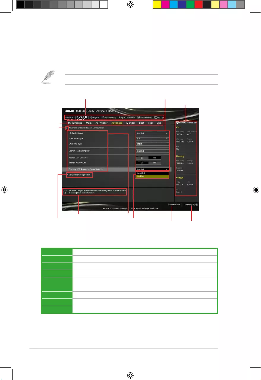
Advanced Mode
The Advanced Mode provides advanced options for experienced end‑users to congure the
BIOS settings. The gure below shows an example of the Advanced Mode. Refer to the
following sections for the detailed congurations.
To access the EZ Mode, click Exit, then select ASUS EZ Mode or press F7.
Menu bar
The menu bar on top of the screen has the following main items:
My Favorites For saving the frequently‑used system settings and conguration
Main For changing the basic system conguration
Ai Tweaker For changing the overclocking settings
Advanced For changing the advanced system settings
Monitor For displaying the system temperature, power status, and changing the
fan settings
Boot For changing the system boot conguration
Tool For conguring options for special functions
Exit For selecting the exit options and loading default settings
Last modified
settings Enters EZ
mode
Hardware information
General help Menu items
Submenu item
Configuration fieldsQuick settings bar
Back button
Menu bar
Drop-down list
E9808_A68HM Series_Manual.indb 8 2014/10/16 10:09:08
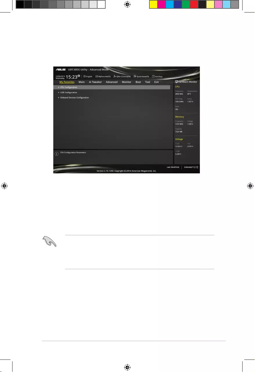
2-9
Adding items to My Favorites
To add frequently‑used BIOS items to My Favorites:
1. Use the arrow keys to select an item that you want to add. When using a mouse, hover
the pointer to the item.
2. Press <F3> on your keyboard or right‑click on your mouse to add the item to My
Favorites page.
You cannot add the following items to My Favorites:
• Items with submenu options
• User‑congurable items such as language and boot device order
• Conguration items such as Memory SPD Information, system time and date
2.3 My Favorites
MyFavorites is your personal space where you can easily save and access your favorite
BIOS items.
E9808_A68HM Series_Manual.indb 9 2014/10/16 10:09:08
2-10
Chapter 2: Getting started
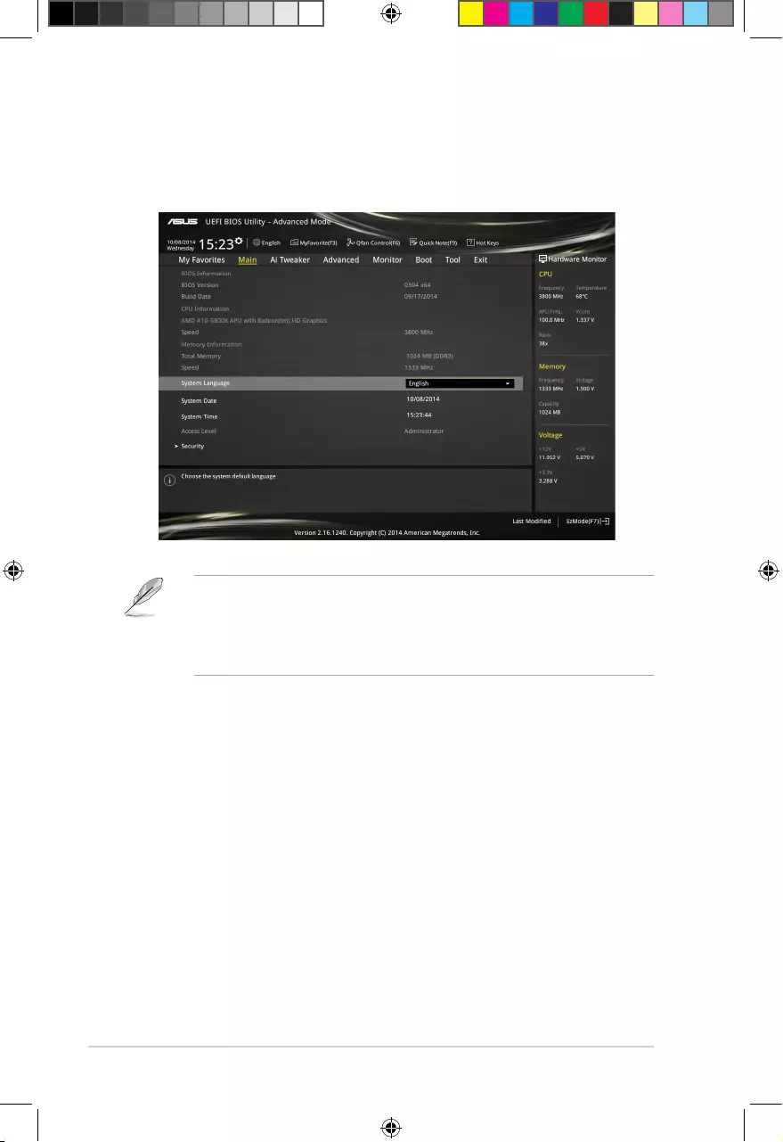
2.4 Main menu
The Main menu screen appears when you enter the Advanced Mode of the BIOS Setup
program. The Main menu provides you an overview of the basic system information, and
allows you to set the system date, time, language, and security settings.
• If you have forgotten your BIOS password, erase the CMOS Real Time Clock (RTC)
RAM to clear the BIOS password. See section 1.6 Headers for information on how to
erase the RTC RAM.
• The Administrator or User Password items on top of the screen show the default
Not Installed. After you set a password, these items show Installed.
E9808_A68HM Series_Manual.indb 10 2014/10/16 10:09:08
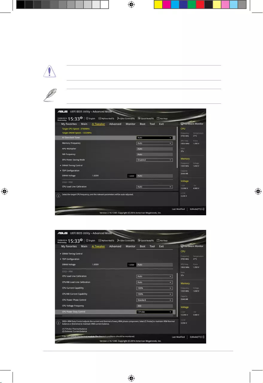
2-11
2.5 Ai Tweaker menu
The Ai Tweaker menu items allow you to congure overclocking‑related items.
Be cautious when changing the settings of the Ai Tweaker menu items. Incorrect eld
values can cause the system to malfunction.
The conguration options for this section vary depending on the CPU and DIMM model you
installed on the motherboard.
Scroll down to display the other items.
E9808_A68HM Series_Manual.indb 11 2014/10/16 10:09:09
2-12
Chapter 2: Getting started
2.6 Advanced menu
The Advanced menu items allow you to change the settings for the CPU and other system
devices.
Be cautious when changing the settings of the Advanced menu items. Incorrect eld values
can cause the system to malfunction.
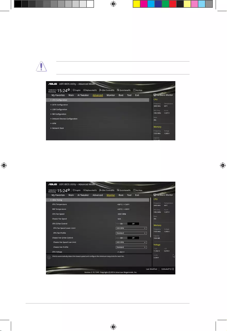
2.7 Monitor menu
The Monitor menu displays the system temperature/power status, and allows you to change
the fan settings.
Scroll down to display the other items.
E9808_A68HM Series_Manual.indb 12 2014/10/16 10:09:10
2‑13
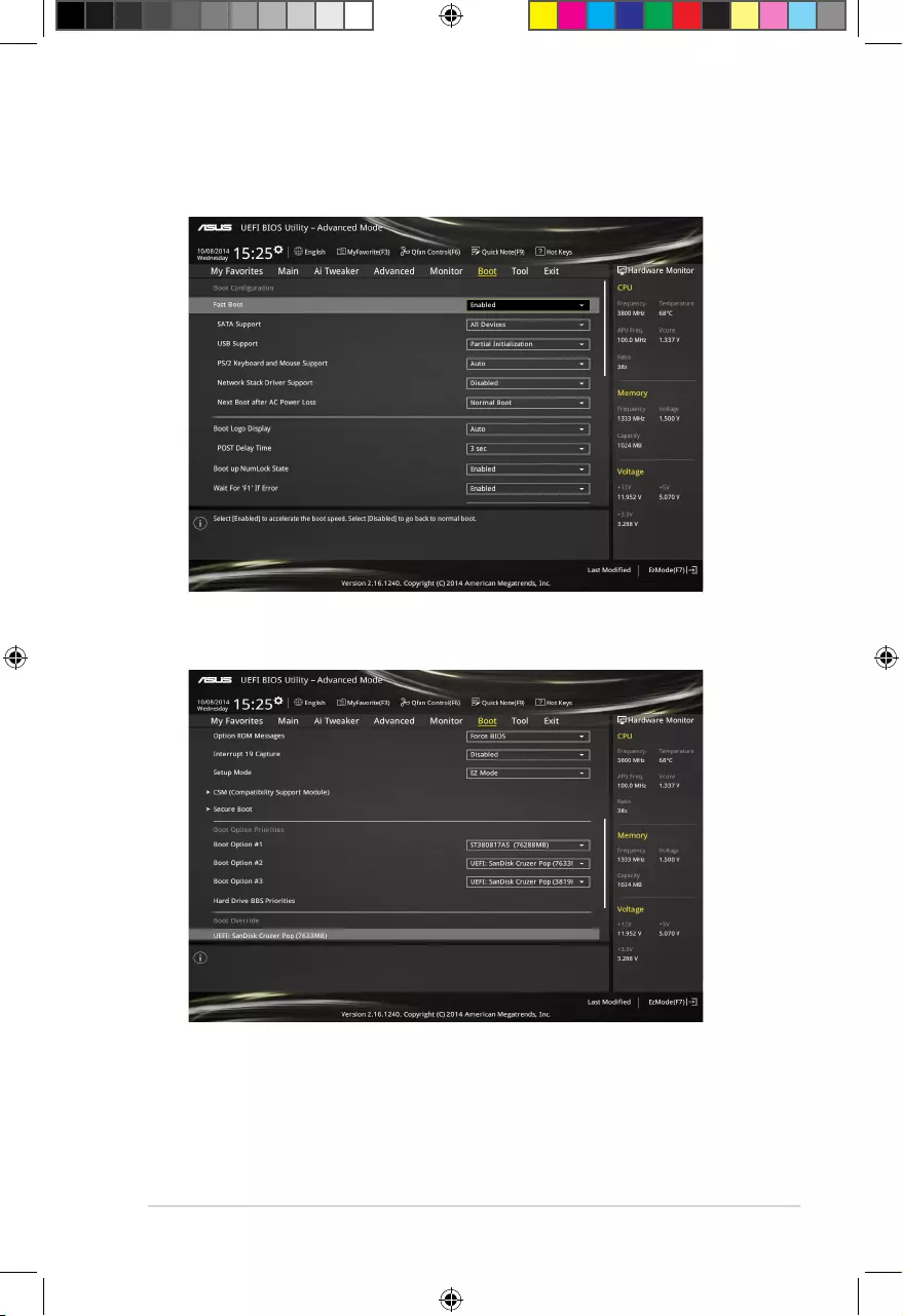
2.8 Boot menu
The Boot menu items allow you to change the system boot options.
Scroll down to display the other items.
E9808_A68HM Series_Manual.indb 13 2014/10/16 10:09:10
2-14
Chapter 2: Getting started
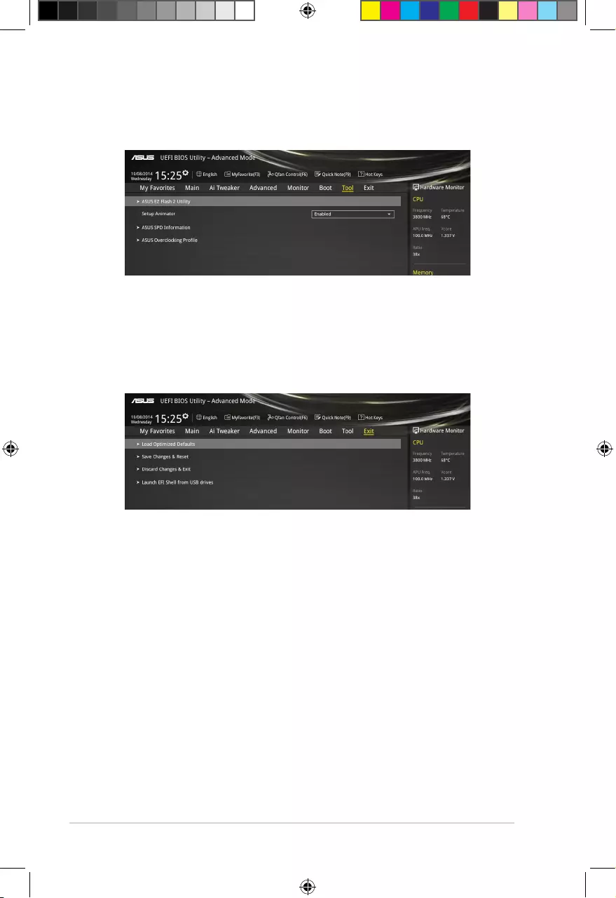
2.9 Tools menu
The Tools menu items allow you to congure options for special functions. Select an item
then press <Enter> to display the submenu.
2.10 Exit menu
The Exit menu items allow you to load the optimal default values for the BIOS items, and
save or discard your changes to the BIOS items. You can access the EZ Mode from the Exit
menu.
E9808_A68HM Series_Manual.indb 14 2014/10/16 10:09:11
A-1
Appendices
Notices
Federal Communications Commission Statement
This device complies with Part 15 of the FCC Rules. Operation is subject to the following two
conditions:
• This device may not cause harmful interference.
• This device must accept any interference received including interference that may cause
undesired operation.
This equipment has been tested and found to comply with the limits for a Class B digital
device, pursuant to Part 15 of the FCC Rules. These limits are designed to provide
reasonable protection against harmful interference in a residential installation. This
equipment generates, uses and can radiate radio frequency energy and, if not installed
and used in accordance with manufacturer’s instructions, may cause harmful interference
to radio communications. However, there is no guarantee that interference will not occur
in a particular installation. If this equipment does cause harmful interference to radio or
television reception, which can be determined by turning the equipment off and on, the user
is encouraged to try to correct the interference by one or more of the following measures:
• Reorient or relocate the receiving antenna.
• Increase the separation between the equipment and receiver.
• Connect the equipment to an outlet on a circuit different from that to which the receiver is
connected.
• Consult the dealer or an experienced radio/TV technician for help.
The use of shielded cables for connection of the monitor to the graphics card is required
toassurecompliancewithFCCregulations.Changesormodicationstothisunitnot
expressly approved by the party responsible for compliance could void the user’s authority
to operate this equipment.
E9808_A68HM Series_Manual.indb 1 2014/10/16 10:09:11
A-2
IC: Canadian Compliance Statement
ComplieswiththeCanadianICES-003ClassBspecications.ThisdevicecomplieswithRSS
210 of Industry Canada. This Class B device meets all the requirements of the Canadian
interference-causing equipment regulations.
This device complies with Industry Canada license exempt RSS standard(s). Operation is
subject to the following two conditions: (1) this device may not cause interference, and (2)
this device must accept any interference, including interference that may cause undesired
operation of the device.
Cut appareil numérique de la Classe B est conforme à la norme NMB-003 du Canada.
Cet appareil numérique de la Classe B respecte toutes les exigences du Règlement sur le
matériel brouilleur du Canada.
Cet appareil est conforme aux normes CNR exemptes de licence d’Industrie Canada. Le
fonctionnement est soumis aux deux conditions suivantes :
(1) cet appareil ne doit pas provoquer d’interférences et
(2) cet appareil doit accepter toute interférence, y compris celles susceptibles de provoquer
un fonctionnement non souhaité de l’appareil.
Canadian Department of Communications Statement
This digital apparatus does not exceed the Class B limits for radio noise emissions from
digital apparatus set out in the Radio Interference Regulations of the Canadian Department
of Communications.
This class B digital apparatus complies with Canadian ICES-003.
VCCI: Japan Compliance Statement
VCCI Class B Statement
This is a Class B product based on the standard of the VCCI Council. If this is used near a
radio or television receiver in a domestic environment, it may cause radio interference. Install
and use the equipment according to the instruction manual.
KC: Korea Warning Statement
E9808_A68HM Series_Manual.indb 2 2014/10/16 10:09:11
A-3
REACH
Complying with the REACH (Registration, Evaluation, Authorisation, and Restriction of
Chemicals) regulatory framework, we published the chemical substances in our products at
ASUS REACH website at http://csr.asus.com/english/REACH.htm.
DO NOT throw the motherboard in municipal waste. This product has been designed to
enable proper reuse of parts and recycling. This symbol of the crossed out wheeled bin
indicates that the product (electrical and electronic equipment) should not be placed in
municipal waste. Check local regulations for disposal of electronic products.
DO NOT throw the mercury-containing button cell battery in municipal waste. This symbol
of the crossed out wheeled bin indicates that the battery should not be placed in municipal
waste.
ASUS Recycling/Takeback Services
ASUS recycling and takeback programs come from our commitment to the highest standards
for protecting our environment. We believe in providing solutions for you to be able to
responsibly recycle our products, batteries, other components as well as the packaging
materials. Please go to http://csr.asus.com/english/Takeback.htm for detailed recycling
information in different regions.
E9808_A68HM Series_Manual.indb 3 2014/10/16 10:09:11

A-4
ASUS contact information
ASUSTeK COMPUTER INC.
Address 15 Li-Te Road, Peitou, Taipei, Taiwan 11259
Telephone +886-2-2894-3447
Fax +886-2-2890-7798
E-mail info@asus.com.tw
Web site www.asus.com/tw/
Technical Support
Telephone +86-21-38429911
Fax +86-21-58668722, ext.9101#
Online support http://www.asus.com/tw/support/
ASUS COMPUTER INTERNATIONAL (America)
Address 800 Corporate Way, Fremont, CA 94539, USA
Telephone +1-510-739-3777
Fax +1-510-608-4555
Web site http://www.asus.com/us/
Technical Support
General support +1-812-282-2787
Support fax +1-812-284-0883
Online support http://www.service.asus.com/
ASUS COMPUTER GmbH (Germany and Austria)
Address Harkort Str. 21-23, D-40880 Ratingen, Germany
Fax +49-2102-959931
Web site http://www.asus.com/de
Online contact http://eu-rma.asus.com/sales
Technical Support
Telephone +49-2102-5789555
Support Fax +49-2102-959911
Online support http://www.asus.com/de/support/
E9808_A68HM Series_Manual.indb 4 2014/10/16 10:09:11
A-5
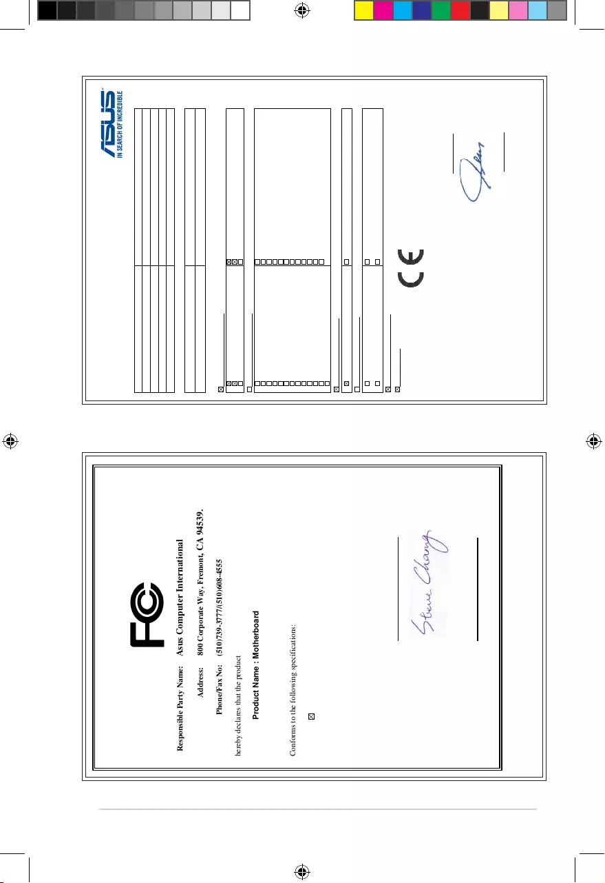
DECLARATION OF CONFORMITY
Per FCC Part 2 Section 2. 1077(a)
Responsible Party Name:
Asus Computer International
Address: 800 Corporate Way, Fremont
, CA 94539.
Phone/Fax No: (510)739-3777/(510)608-4555
hereby declares that the product
Product Name : Motherboard
Model Number : A68HM-E A68HM-E
Conforms to the following specifications:
FCC Part 15, Subpart B, Unintentional Radiators
Supplementary Information:
This device complies with part 15 of the FCC Rules. Operation is subject to the
following two conditions: (1) This device may not cause harmful interference,
and (2) this device must accept any interference received, including interference
that may cause undesired operation.
Representative Person’s Name : Steve Chang / President
Signature :
Date : Oct. 10, 2014
Ver. 140331
A68HM-E Model Number : A68HM-K
,
EC Declaration of Conformity
We, the undersigned,
Manufacturer: ASUSTeK COMPUTER INC.
Address: 4F, No. 150, LI-TE Rd., PEITOU, TAIPEI 112, TAIWAN
Authorized representative in Europe: ASUS COMPUTER GmbH
Address, City: HARKORT STR. 21-23, 40880 RATINGEN
Country: GERMANY
declare the following apparatus:
Product name : Motherboard
Model name : A68HM-K, A68HM-E
conform with the essential requirements of the following directives:
2004/108/EC-EMC Directive
EN 55022:2010+AC:2011
EN 61000-3-2:2006+A2:2009
EN 55013:2001+A1:2003+A2:2006
EN 55024:2010
EN 61000-3-3:2008
EN 55020:2007+A11:2011
1999/5/EC-R&TTE Directive
EN 300 328 V1.7.1(2006-10)
EN 300 440-1 V1.6.1(2010-08)
EN 300 440-2 V1.4.1(2010-08)
EN 301 511 V9.0.2(2003-03)
EN 301 908-1 V5.2.1(2011-05)
EN 301 908-2 V5.2.1(2011-07)
EN 301 893 V1.6.1(2011-11)
EN 302 544-2 V1.1.1(2009-01)
EN 302 623 V1.1.1(2009-01)
EN 50360:2001
EN 62479:2010
EN 50385:2002
EN 62311:2008
EN 301 489-1 V1.9.2(2011-09)
EN 301 489-3 V1.4.1(2002-08)
EN 301 489-4 V1.4.1(2009-05)
EN 301 489-7 V1.3.1(2005-11)
EN 301 489-9 V1.4.1(2007-11)
EN 301 489-17 V2.2.1(2012-09)
EN 301 489-24 V1.5.1(2010-09)
EN 302 326-2 V1.2.2(2007-06)
EN 302 326-3 V1.3.1(2007-09)
EN 301 357-2 V1.4.1(2008-11)
EN 302 291-1 V1.1.1(2005-07)
EN 302 291-2 V1.1.1(2005-07)
2006/95/EC-LVD Directive
EN 60950-1 / A12:2011 EN 60065:2002 / A12:2011
2009/125/EC-ErP Directive
Regulation (EC) No. 1275/2008
Regulation (EC) No. 642/2009
Regulation (EC) No. 278/2009
Regulation (EC) No. 617/2013
2011/65/EU-RoHS Directive
Ver. 140331
CE marking
Declaration Date: 10/10/2014
Year to begin affixing CE marking: 2014
Position : CEO
Name :
Jerry Shen
Signature :
__________
(EC conformity marking)
E9808_A68HM Series_Manual.indb 5 2014/10/16 10:09:12
-
Драйверы
35
-
Инструкции по эксплуатации
4
Языки:
ASUS A68HM-K инструкция по эксплуатации
(47 страниц)
- Языки:Английский
-
Тип:
PDF -
Размер:
4.35 MB -
Описание:
A68HM series user’s manual (English)
Просмотр
ASUS A68HM-K инструкция по эксплуатации
(48 страниц)
- Языки:Китайский
-
Тип:
PDF -
Размер:
4.81 MB -
Описание:
A68HM series user’s manual (Simplified Chinese)
Просмотр
ASUS A68HM-K инструкция по эксплуатации
(46 страниц)
- Языки:Китайский
-
Тип:
PDF -
Размер:
4.46 MB -
Описание:
A68HM series user’s manual (Traditional Chinese)
Просмотр
ASUS A68HM-K инструкция по эксплуатации
(2 страницы)
-
Тип:
PDF -
Размер:
1.43 MB -
Описание:
A68HM Series Quick Start Guide for Multi-language
Просмотр
На NoDevice можно скачать инструкцию по эксплуатации для ASUS A68HM-K. Руководство пользователя необходимо для ознакомления с правилами установки и эксплуатации ASUS A68HM-K. Инструкции по использованию помогут правильно настроить ASUS A68HM-K, исправить ошибки и выявить неполадки.
Найди любой мануал:
Например: Sony VGN-FW460J/T
Вы можете бесплатно скачать Инструкция по эксплуатации для ASUS A68HM-K C9808.
Также вы сможете прочесть онлайн этот документ без скачивания.
Скачать Инструкция по эксплуатации для ASUS A68HM-K C9808
Тип файла
PDF
Размер
4.81 Mb
Кол-во страниц
48
Просмотров
2099
Читать онлайн Инструкция по эксплуатации для ASUS A68HM-K C9808 (Страница 1)

Другие Материнские платы ASUS A68HM-K C9808
Топ ASUS Материнские платы
Ранее вы смотрели
Эта страница полезна для вас? Поделитесь ссылкой:
Manufacturer:ASUS
Category:Computers & Peripherals
Device:ASUS A68HM-K
Name:Device QVL
Language:Multilingual
Pages:18
Size:227.49 KB
Manufacturer:ASUS
Category:Computers & Peripherals
Device:ASUS A68HM-K
Name:A68HM series user’s manual (Traditional Chinese)
Language:中文(繁體)
Pages:46
Size:4.46 MB
Manufacturer:ASUS
Category:Computers & Peripherals
Device:ASUS A68HM-K
Name:A68HM series user’s manual (Simplified Chinese)
Language:中文(简体)
Pages:48
Size:4.81 MB
Manufacturer:ASUS
Category:Computers & Peripherals
Device:ASUS A68HM-K
Name:A68HM series user’s manual (English)
Language:English
Pages:47
Size:4.35 MB
Manufacturer:ASUS
Category:Computers & Peripherals
Device:ASUS A68HM-K
Name:A68HM Series Quick Start Guide
Language:Multilingual
Pages:2
Size:1.43 MB
Manufacturer:ASUS
Category:Computers & Peripherals
Device:ASUS A68HM-K
Name:FM2+ 2DIMM Kaveri Memory QVL update
Language:Multilingual
Pages:5
Size:379.52 KB
Manufacturer:ASUS
Category:Computers & Peripherals
Device:ASUS A68HM-K
Name:FM2_2DIMM_Richland_160427
Pages:4
Size:348.40 KB
Manufacturer:ASUS
Category:Computers & Peripherals
Device:ASUS A68HM-K
Name:FM2+ DIMM KAVERI
Pages:5
Size:364.16 KB
Manufacturer:ASUS
Category:Computers & Peripherals
Device:ASUS A68HM-K
Name:FM2+ DIMM_Richland
Pages:4
Size:335.13 KB
Manufacturer:ASUS
Category:Computers & Peripherals
Device:ASUS A68HM-K
Name:FM2+ 2DIMM Kaveri Memory QVL update
Language:Multilingual
Pages:5
Size:44.07 KB
Manufacturer:ASUS
Category:Computers & Peripherals
Device:ASUS A68HM-K
Name:FM2+ 2DIMM Richland Memory QVL update
Language:Multilingual
Pages:4
Size:72.89 KB
Manufacturer:ASUS
Category:Computers & Peripherals
Device:ASUS A68HM-K
Name:FM2_2DIMM_KAVERI_150727
Pages:5
Size:375.69 KB
Manufacturer:ASUS
Category:Computers & Peripherals
Device:ASUS A68HM-K
Name:FM2_2DIMM_Richland_150727
Pages:4
Size:343.84 KB
Manufacturer:ASUS
Category:Computers & Peripherals
Device:ASUS A68HM-K
Name:New_SSD_List
Pages:1
Size:18.19 KB