
Manual
View the manual for the Asrock FM2A68M-DG3+ here, for free. This user manual comes under the category motherboards and has been rated by 1 people with an average of a 8.8. This manual is available in the following languages: English. Do you have a question about the Asrock FM2A68M-DG3+?
Ask your question here
Asrock FM2A68M-DG3+ specifications
Below you will find the product specifications and the manual specifications of the Asrock FM2A68M-DG3+.
Supported memory types
DDR3-SDRAM
Processor manufacturer
AMD
Supported storage drive interfaces
SATA III
General
| Brand | Asrock |
| Model | FM2A68M-DG3+ | 90-MXGWQ0-A0UAYZ |
| Product | motherboard |
| EAN | 4717677325065, 4717677325225, 5053118066449, 7805714484374, 5706998562425 |
| Language | English |
| Filetype | User manual (PDF) |
Memory
| Supported memory types | DDR3-SDRAM |
| Memory slots type | DIMM |
| Memory channels | Dual-channel |
| Supported memory clock speeds | 1066,1333,1600 MHz |
| Maximum internal memory | 32 GB |
| Unbuffered memory | Yes |
| Number of memory slots | 2 |
Processor
| Processor manufacturer | AMD |
| Compatible processor series | — |
| Processor socket | Socket FM2+ |
Internal I/O
| USB 2.0 connectors | 3 |
| USB 3.2 Gen 1 (3.1 Gen 1) connectors | 0 |
| CPU fan connector | Yes |
| Number of COM connectors | 1 |
| ATX Power connector (24-pin) | Yes |
| Chassis intrusion connector | Yes |
| Number of chassis fan connectors | 1 |
| Number of Parallel ATA connectors | — |
| Front panel audio connector | Yes |
| Power fan connector | Yes |
| TPM connector | Yes |
| Peripheral (Molex) power connectors (4-pin) | 1 |
| Number of SATA II connectors | 0 |
| Number of SATA III connectors | 4 |
Storage controllers
| Supported storage drive interfaces | SATA III |
| RAID levels | 0, 1,10 |
Rear panel I/O ports
| USB 2.0 ports quantity | 4 |
| USB 3.2 Gen 1 (3.1 Gen 1) Type-A ports quantity | 2 |
| Ethernet LAN (RJ-45) ports | 1 |
| eSATA ports quantity | 0 |
| PS/2 ports quantity | 1 |
| Firewire (IEEE 1394) ports | 0 |
| Headphone outputs | 2 |
| Microphone in | Yes |
| VGA (D-Sub) ports quantity | 1 |
| DVI-D ports quantity | 1 |
| HDMI ports quantity | 0 |
Network
| Ethernet LAN | Yes |
| LAN controller | Realtek RTL8111GR |
| Wake-on-LAN ready | Yes |
| Ethernet interface type | Gigabit Ethernet |
Features
| Component for | PC |
| Motherboard chipset family | AMD |
| Motherboard chipset | AMD A68 |
| Motherboard form factor | micro ATX |
| Audio output channels | 5.1 channels |
| Audio chip | Realtek ALC662 |
| Windows operating systems supported | Yes |
| Certification | — FCC, CE, WHQL\r\n- ErP/EuP ready (ErP/EuP ready power supply is required) |
| Power source type | ATX |
Graphics
| Maximum graphics card memory | 2048 MB |
| Parallel processing technology support | — |
| HDCP | Yes |
| Graphics card family | AMD |
| DirectX version | 11.1 |
| Maximum resolution | 2560 x 1600 pixels |
Expansion slots
| PCI Express x1 (Gen 2.x) slots | 1 |
| PCI Express x16 (Gen 3.x) slots | 1 |
| PCI slots | 1 |
BIOS
| BIOS type | UEFI AMI |
| BIOS memory size | 64 Mbit |
| ACPI version | 1.1 |
Weight & dimensions
Packaging content
| Cables included | SATA |
| Drivers included | Yes |
| Trial software | AntiVirus Software, Start8 |
Other features
| Quick installation guide | Yes |
Logistics data
| Harmonized System (HS) code | 84733020 |
show more
Frequently asked questions
Can’t find the answer to your question in the manual? You may find the answer to your question in the FAQs about the Asrock FM2A68M-DG3+ below.
What is the width of the Asrock FM2A68M-DG3+?
The Asrock FM2A68M-DG3+ has a width of 218 mm.
What is the depth of the Asrock FM2A68M-DG3+?
The Asrock FM2A68M-DG3+ has a depth of 188 mm.
What certifications does the Asrock FM2A68M-DG3+ have?
The Asrock FM2A68M-DG3+ has the following certifications: — FCC, CE, WHQL\r\n- ErP/EuP ready (ErP/EuP ready power supply is required).
Is the manual of the Asrock FM2A68M-DG3+ available in English?
Yes, the manual of the Asrock FM2A68M-DG3+ is available in English .
Is your question not listed? Ask your question here

FM2A68M -DG3+FM2A68M -DG3+
FM2A68M —DG3+FM2A68M —DG3+
Version 1.0
Published September 2014
Copyright©2014 ASRock INC. All rights reserved.
Copyright Notice:
No part of this documentation may be reproduced, transcribed, transmitted, or
translated in any language, in any form or by any means, except duplication of
documentation by the purchaser for backup purpose, without written consent of
ASRock Inc.
Products and corporate names appearing in this documentation may or may not
be registered trademarks or copyrights of their respective companies, and are used
only for identication or explanation and to the owners’ benet, without intent to
infringe.
Disclaimer:
Specications and information contained in this documentation are furnished for
informational use only and subject to change without notice, and should not be
constructed as a commitment by ASRock. ASRock assumes no responsibility for
any errors or omissions that may appear in this documentation.
With respect to the contents of this documentation, ASRock does not provide
warranty of any kind, either expressed or implied, including but not limited to
the implied warranties or conditions of merchantability or tness for a particular
purpose.
In no event shall ASRock, its directors, ocers, employees, or agents be liable for
any indirect, special, incidental, or consequential damages (including damages for
loss of prots, loss of business, loss of data, interruption of business and the like),
even if ASRock has been advised of the possibility of such damages arising from any
defect or error in the documentation or product.
is device complies with Part 15 of the FCC Rules. Operation is subject to the following
two conditions:
(1) this device may not cause harmful interference, and
(2) this device must accept any interference received, including interference that
may cause undesired operation.
CALIFORNIA, USA ONLY
e Lithium battery adopted on this motherboard contains Perchlorate, a toxic substance
controlled in Perchlorate Best Management Practices (BMP) regulations passed by the
California Legislature. When you discard the Lithium battery in California, USA, please
follow the related regulations in advance.
“Perchlorate Material-special handling may apply, see www.dtsc.ca.gov/hazardouswaste/
perchlorate”
ASRock Website: http://www.asrock.com

Contents
1. Introduction 1
1.1 Package Contents 1
1.2 Specications 2
1.3 Motherboard Layout 6
1.4 I/O Panel 8
2. Installation 9
2.1 CPU Installation 10
2.2 Installation of CPU Fan and Heatsink 11
2.3 Installation of Memory Modules (DIMM) 12
2.4 Expansion Slots (PCI and PCI Express Slots) 14
2.5 Jumpers Setup 15
2.6 Onboard Headers and Connectors 16
2.7 AMD Dual Graphics Operation Guide 20
3. Software and Utilities Operation 22
4. UEFI SETUP UTILITY 38
4.1 Introduction 38
4.1.1 UEFI Menu Bar 38
4.1.2 Navigation Keys 39
4.2 Main Screen 39
4.3 OC Tweaker Screen 40
4.4 Advanced Screen 43
4.4.1 CPU Conguration 44

4.4.2 North Bridge Conguration 45
4.4.3 South Bridge Conguration 46
4.4.4 Storage Conguration 47
4.4.5 Super IO Conguration 48
4.4.6 ACPI Conguration 49
4.4.7 USB Conguration 51
4.5 Tool 53
4.6 Hardware Health Event Monitoring Screen 56
4.7 Boot Screen 57
4.8 Security Screen 59
4.9 Exit Screen 60
FM2A68M-DG3+
1. Introduction
Thank you for purchasing ASRock FM2A68M-DG3+ motherboard, a reliable moth-
erboard produced under ASRock’s consistently stringent quality control. It delivers
excellent performance with robust design conforming to ASRock’s commitment to
quality and endurance.
In this documentation, Chapter 1 and 2 contains the introduction of the motherboard
and step-by-step installation guides. Chapter 3 contains the operation guide of the
software and utilities. Chapter 4 contains the conguration guide of the BIOS setup.
Because the motherboard specications and the BIOS software might
be updated, the content of this manual will be subject to change without
notice. In case any modications of this manual occur, the updated ver—
sion will be available on ASRock website without further notice. You may
nd the latest VGA cards and CPU support lists on ASRock website as
well. ASRock website http://www.asrock.com
If you require technical support related to this motherboard, please visit
our website for specic information about the model you are using.
www.asrock.com/support/index.asp
1.1 Package Contents
ASRock FM2A68M-DG3+ Motherboard (Micro ATX Form Factor)
ASRock FM2A68M-DG3+ Quick Installation Guide
ASRock FM2A68M-DG3+ Support CD
2 x Serial ATA (SATA) Data Cables (Optional)
1 x I/O Panel Shield
English
1

1.2 Specications
Platform
CPU
Chipset
Memor y
Expansion
Slot
• Micro ATX Form Factor
• All Solid Capacitor design
• High Density Glass Fabric PCB
• Supports Socket FM2+ 95W / FM2 100W processors
• AMD A68H (Bolton-D2H)
• Dual Channel DDR3 Memory Technology
• 2 x DDR3 DIMM Slots
• Supports DDR3 2400+(OC)/2133(OC)/1866
(OC)/1600/1333/1066 non-ECC, un-buffered memory
(see CAUTION 1)
• Max. capacity of system memory: 32GB
(see CAUTION 2)
• Supports Intel® Extreme Memory Prole (XMP) 1.3 / 1.2
• Supports AMD Memor y Prole Technology (AMP) up to
AMP 2400
• 1 x PCI Express 3.0 x16 Slot (PCIE1@ x16 mode)
* PCIE 3.0 is only supported with FM2+ CPU. With FM2
CPU, it only supports PCIE 2.0.
• 1 x PCI Express 2.0 x1 Slot
• 1 x PCI Slot
• Supports AMD Dual Graphics
English
2
Graphics
• Integrated AMD RadeonTM R7/R5 Series Graphics in
A-series APU
• DirectX 11.1, Pixel Shader 5.0 with FM2+ CPU. DirectX
11, Pixel Shader 5.0 with FM2 CPU.
• Max. shared memory 2GB
• Dual graphics output options: support DVI-D and D-Sub
by independent display controllers
• Supports Dual-link DVI-D with max. resolution up to
2560×1600 @ 60Hz
• Suppor ts D-Sub with max. resolution up to 1920×1200 @
60Hz

• Supports AMD Steady VideoTM 2.0: New video post
processing capability for automatic jitter reduction on
home/online video
• Supports HDCP with DVI-D Port
• Supports Full HD 1080p Blu-ray (BD) playback with
DVI-D Port
FM2A68M-DG3+
Audio
LAN
Rear
Panel I/O
• 5.1 CH HD Audio (Realtek ALC662 Audio Codec)
• Supports Surge Protection (ASRock Full Spike Protec-
tion)
• PCIE x1 Gigabit LAN 10/100/1000 Mb/s
• Realtek RTL8111GR
• Supports Wake-On-WAN
• Supports Wake-On-LAN
• Supports Lightning/ESD Protection (ASRock Full Spike
Protection)
• Supports L AN Cable Detection
• Supports Energy Efcient Ethernet 802.3az
• Supports PXE
• 1 x PS/2 Mouse/Keyboard Port
• 1 x D-Sub Por t
• 1 x DVI-D Port
• 4 x USB 2.0 Ports (Supports ESD Protection (ASRock
Full Spike Protection))
• 2 x USB 3.0 Ports (AMD A68H (Bolton-D2H)) (Supports
ESD Protection (ASRock Full Spike Protection))
• 1 x RJ -45 LAN Por t with LED (ACT/LINK LED and
SPEED LED)
• HD Audio Jacks: Line in / Front Speaker / Microphone
Storage
Connector
• 4 x SATA3 6.0 Gb/s Connectors, support RAID (RAID 0,
RAID 1 and RAID 10), NCQ, AHCI and Hot Plug
• 1 x Print Port Header
• 1 x COM Port Header
• 1 x Chassis Intrusion Header
• 1 x TPM Header
English
3

• 1 x CPU Fan Connector (4-pin)
• 1 x Chassis Fan Connector (4-pin)
• 1 x Power Fan Connector (3-pin)
• 1 x 24 pin ATX Power Connector
• 1 x 4 pin 12V Power Connector
• 1 x Front Panel Audio Connector
• 2 x USB 2.0 Headers (Support 4 USB 2.0 ports)
(Supports ESD Protection (ASRock Full Spike Protec-
tion))
• 1 x Flexible USB 2.0 Header (Supports 2 USB 2.0 ports)
(Supports ESD Protection (ASRock Full Spike Protec-
tion))
* This Flexible USB 2.0 header allows users to connect a
front USB 3.0 panel, and support two USB ports with 2.0/1.1
data rate.
English
BIOS
Feature
Hardware
Monitor
OS
• 64Mb AMI UEFI Legal BIOS with GUI suppor t
• Supports “Plug and Play”
• ACPI 1.1 Compliant wake up events
• Supports jumperfree
• SMBIOS 2.3.1 support
• DRAM, CPU Voltage multi-adjustment
• CPU temperature sensing
• Chassis temperature sensing
• CPU Fan Tachometer
• Chassis Fan Tachometer
• CPU/Chassis Quiet Fan
• CPU/Chassis Fan multi-speed control
• CASE OPEN detection
• Voltage monitoring: +12V, +5V, +3.3V, Vcore
• Microsoft® Windows® 10 32-bit / 10 64-bit / 8.1 32-bit / 8.1
64-bit / 8 32-bit / 8 64-bit / 7 32-bit / 7 64-bit
* For the updated Windows® 10 driver, please visit
ASRock’s website for details: http://w ww.asrock.com
* Carrizo FM2r2 processor supports Windows® 10 64-bit/
8.1 64-bit / 7 32-bit / 7 64-bit only.
4

FM2A68M-DG3+
Certications
* For detailed product information, please visit our website: http://w ww.asrock.com
WARNING
Please realize that there is a certain risk involved with overclocking,
including adjusting the setting in the BIOS, applying Untied Overclocking
Technology, or using third-party overclocking tools. Overclocking may
affect your system’s stability, or even cause damage to the components
and devices of your system. It should be done at your own risk and
expense. We are not responsible for possible damage caused by
overclocking.
• FCC, CE, WHQL
• ErP/EuP Ready (ErP/EuP ready power supply is re-
quired)
CAUTION!
1. Whether 2400/2133/1866/1600MHz memory speed is support-2400/2133/1866/1600MHz memory speed is support-1866/1600MHz memory speed is support-
ed depends on the CPU you adopt. If you want to adopt DDR3
2400/2133/1866/1600 memory module on this motherboard,
please refer to the memory support list on our website for the
compatible memory modules.
ASRock website http://www.asrock.com
2. Due to the operating system limitation, the actual memory size
may be less than 4GB for the reservation for system usage un-
der Windows® 10 / 8.1 / 8 / 7. For Windows® 64-bit OS with 64-
bit CPU, there is no such limitation. You can use ASRock XFast
RAM to utilize the memory that Windows® cannot use.
English
5
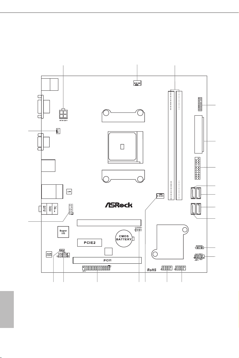
1.3 Motherboard Layout
SOC KE T F M2b
3
1
ATXP WR 1
CPU_FAN 1
64Mb
BIOS
FM2A68M-D G 3+
DDR 3_A 1 ( 64 bit , 2 40- pin mo dul e)
DDR 3_B 1 ( 64 bit , 2 40- pin mo dul e)
USB_7_ 8
13
16
17
12
USB 3.0
T: USB 3
B: U SB4
RJ- 45 L AN
USB 2.0
T: USB 5
B: U SB6
PWR_FAN1
2
5
4
21
19
AMD
A68 H
(Bo lt on- D2H )
Chi ps et
USB 2. 0
T: USB1
B: USB 2
PS2
Keybo ard
/Mous e
VGA 1
DVI1
7
SATA_
2
SATA_
4
SATA_
1
SATA_
3
PCI Ex pre ss 3.0
8
9
6
10
11
USB_9_ 10
PCIE1
1
CI1
HD_AUD IO1
1
1518
CHA_FAN 1
14
1
TPMS1
1
USB_11 _ 12
20
English
6

No. Description
1 ATX 12V Power Connector (ATX12V1)
2 CPU Fan Connector (CPU_FAN1)
3 2 x 240-pin DDR3 DIMM Slots (DDR3_A1, DDR3_B1)
4 TPM Header (TPMS1)
5 ATX Power Connector (ATXPWR1)
6 Flexible USB 2.0 Header (USB_11_12)*
7 SATA3 Connector (SATA_2)
8 SATA3 Connector (SATA_4)
9 SATA3 Connector (SATA_3)
10 SATA3 Connector (SATA_1)
11 Chassis Speaker Header (SPEAKER1)
12 System Panel Header (PANEL1)
13 USB 2.0 Header (USB_9_10)
14 USB 2.0 Header (USB_7_8)
15 Chassis Fan Connector (CHA_FAN1)
16 Clear CMOS Jumper (CLRCMOS1)
17 Print Port Header (LPT1)
18 COM Por t Header (COM1)
19 Chassis Intrusion Header (CI1)
20 Front Panel Audio Header (HD_AUDIO1)
21 Power Fan Connector (PWR_FAN1)
FM2A68M-DG3+
* This Flexible USB 2.0 header allows users to connect a front USB 3.0
panel, and support two USB ports with 2.0/1.1 data rate.
English
7
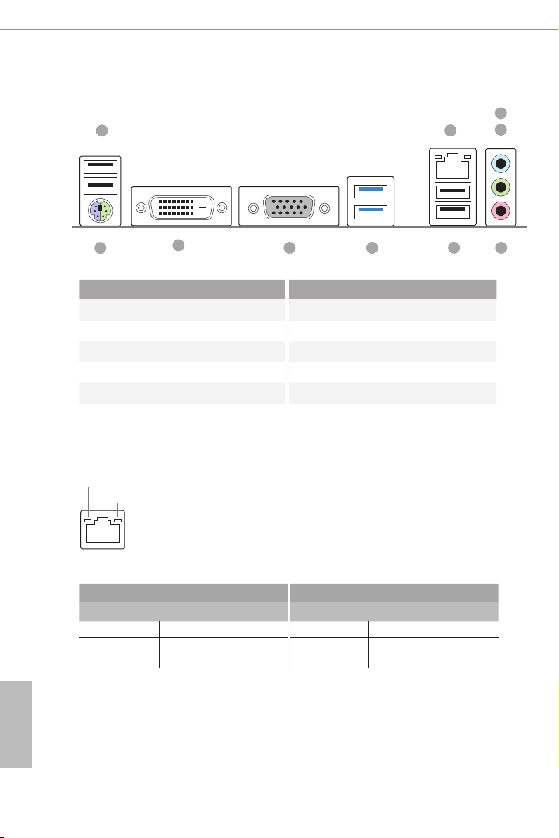
1.4 I/O Panel
1
3
2
4
10
9
No. Description No. Description
1 USB 2.0 Ports (USB_1_2) 6 USB 2.0 Ports (USB_5_6)
2 LAN RJ-45 Port* 7 USB 3.0 Ports (USB_3_4)
3 Line In (Light Blue) 8 D-Sub Port
4 Front Speaker (Lime) 9 DVI-D Port
5 Microphone (Pink) 10 PS/2 Mouse/Keyboard Port
* There are two LEDs o n the LAN p ort. Please refer to the table below for the LAN port LED indica-
tions.
ACT/LINK L ED
SPEED LE D
LAN Por t
Activity / Link LED Speed LED
Status Description Status Description
Off No Link Off 10Mbps connection
Blinking Data Activity Orange 100Mbps connection
On Link Green 1Gbps connection
5678
English
8

FM2A68M-DG3+
2. Installation
This is a Micro ATX form factor motherboard. Before you install the motherboard,
study the conguration of your chassis to ensure that the motherboard ts into it.
Pre-installation Precautions
Take note of the following precautions before you install motherboard
components or change any motherboard settings.
Before you install or remove any component, ensure that the
power is switched off or the power cord is detached from the
power supply. Failure to do so may cause severe damage to the
motherboard, peripherals, and/or components.
1. Unplug the power cord from the wall socket before touching any
component.
2. To avoid damaging the motherboard components due to static elec-
tricity, NEVER place your motherboard directly on the carpet or the
like. Also remember to use a grounded wrist strap or touch a safety
grounded object before you handle components.
3. Hold components by the edges and do not touch the ICs.
4. Whenever you uninstall any component, place it on a grounded anti-
static pad or in the bag that comes with the component.
5. When placing screws into the screw holes to secure the mother-
board to the chassis, please do not over-tighten the screws! Doing
so may damage the motherboard.
English
9
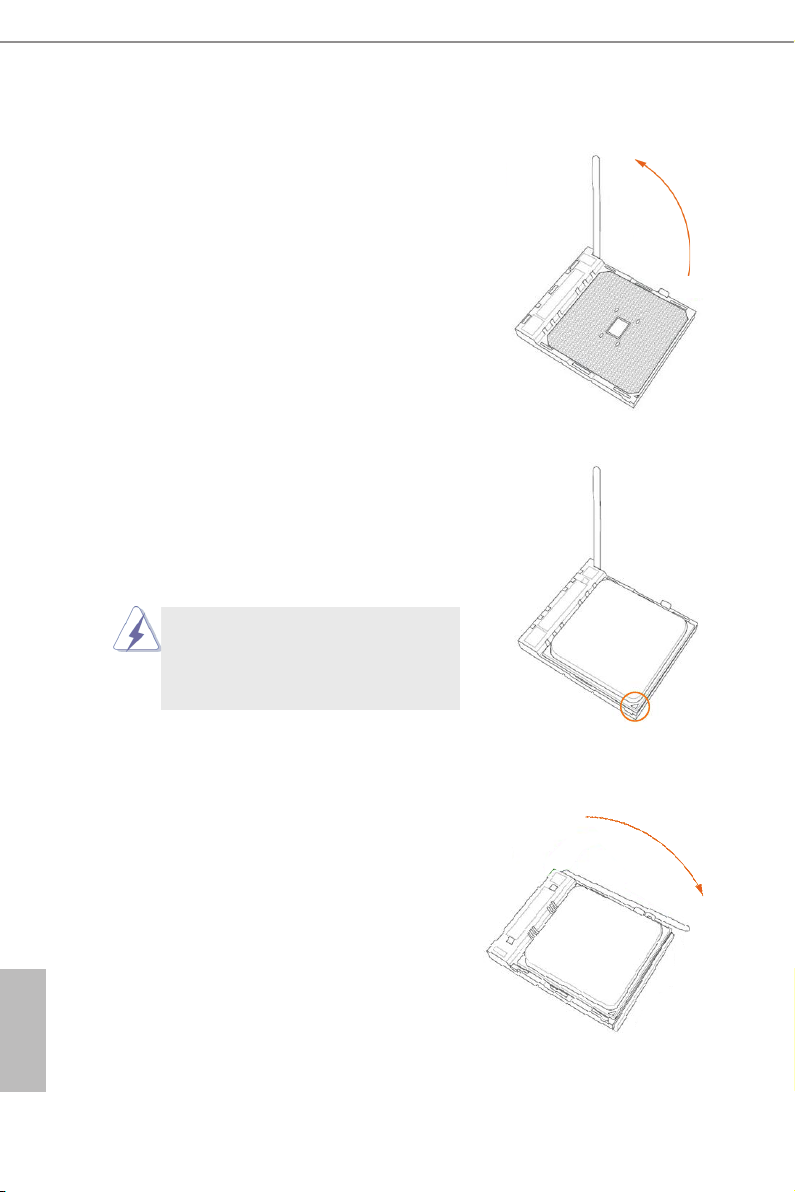
2.1 CPU Installation
Step 1. Unlock the socket by lifting the lever up
to a 90
Step 2. Position the CPU directly above the
socket such that the CPU corner with
the golden triangle matches the socket
corner with a small triangle.
Step 3. Carefully insert the CPU into the
socket until it ts in place.
o
angle.
The CPU ts only in one correct
orientation. DO NOT force the CPU
into the socket to avoid bending of
the pins.
English
10
Step 4. When the CPU is in place, press it
rmly on the socket while you push
down the socket lever to secure the
CPU. The lever clicks on the side tab
to indicate that it is locked.

2.2 Installation of CPU Fan and Heatsink
After you install the CPU into this motherboard, it is necessary to install a
larger heatsink and cooling fan to dissipate heat. You also need to spray
thermal grease between the CPU and the heatsink to improve heat dis-
sipation. Make sure that the CPU and the heatsink are securely fastened
and in good contact with each other. Then connect the CPU fan to the
CPU FAN connector (CPU_FAN1, see Page 6, No. 2). For proper instal-
lation, please kindly refer to the instruction manuals of the CPU fan and
the heatsink.
FM2A68M-DG3+
11
English
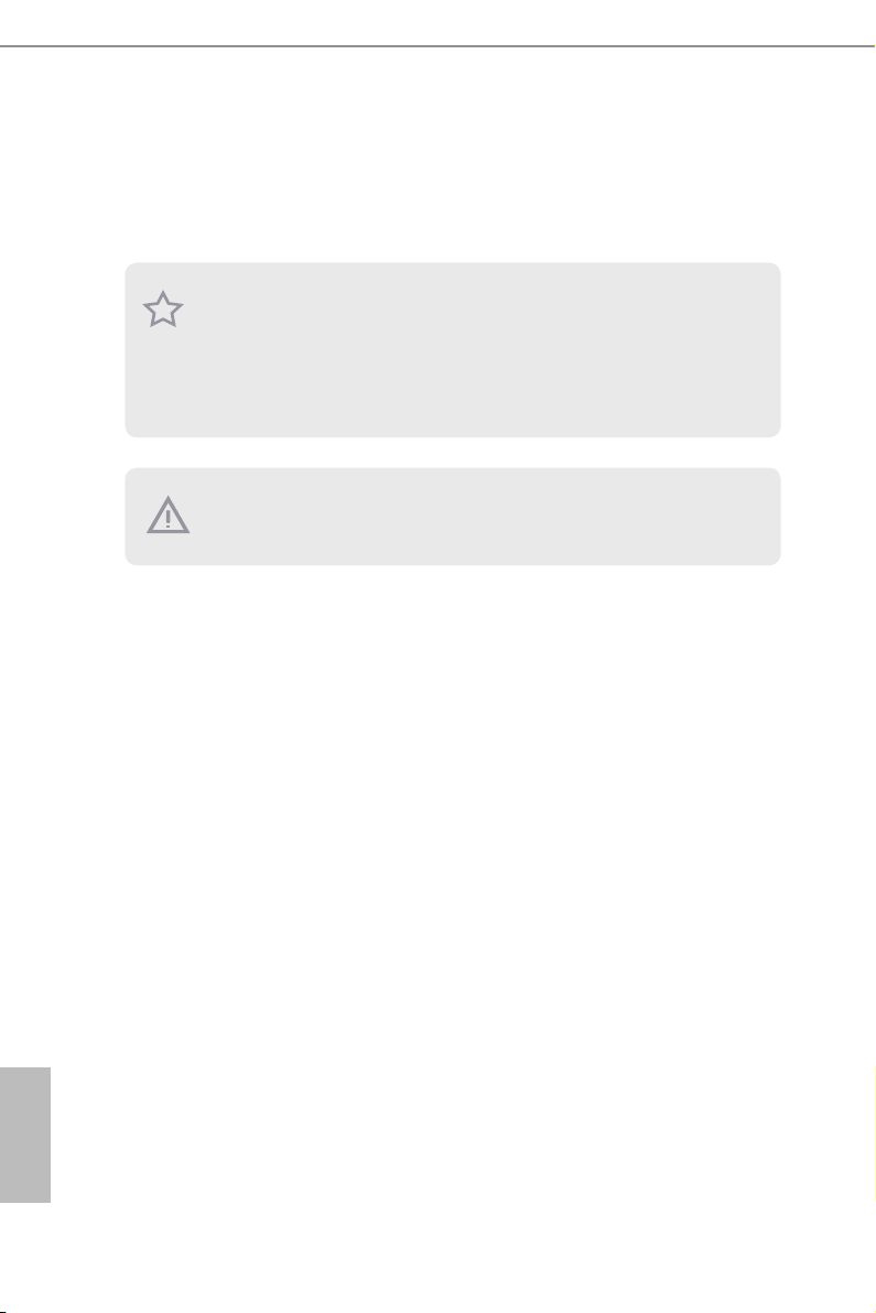
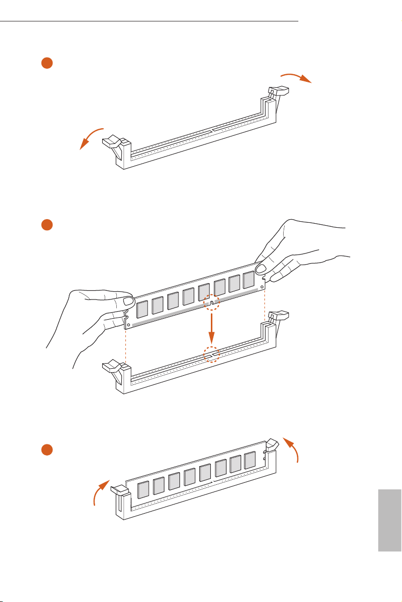
2.3 Installation of Memory Modules (DIMM)
This motherboard provides two 240-pin DDR3 (Double Data Rate 3) DIMM
slots, and supports Dual Channel Memory Technology.
1. For dual channel conguration, you always need to install identical (the same
brand, speed, size and chip-type) DDR3 DIMM pairs.
2. It is unable to activate Dual Ch annel Memory Technology with only one memory
module install ed.
3. It is not allowed to install a DDR or DDR 2 memory module into a DDR3 slot;
otherwise, this mothe rboard and DIMM may be damaged.
e DIMM only ts in one correct orientation. It wil l cause permanent damage to
the mothe rboard and the DIMM if you force th e DIMM into the slot at incorrect
orientation.
English
12
FM2A68M-DG3+
1
2
3
English
13

2.4 Expansion Slots (PCI and PCI Express Slots)
There are 1 PCI slot and 2 PCI Express slots on this motherboard.
Before installing an expansion card, please make sure that the power supply
is switched off or the power cord is unplugged. Please r ead the documentation of the expansion card and make necessary hardware s ettings for the
PCI Slot: PCI slot is used to install expansion cards that have the 32-bit PCI
interface.
PCIE Slots:
PCIE1 (PCIe 3.0 x16 slot) is used for PCI Express x16 lane width
PCIE2 (PCIe 2.0 x1 slot) is used for PCI Express cards with x1 lane
card before you star t the installation.
graphics cards.
width cards.
English
14
FM2A68M-DG3+
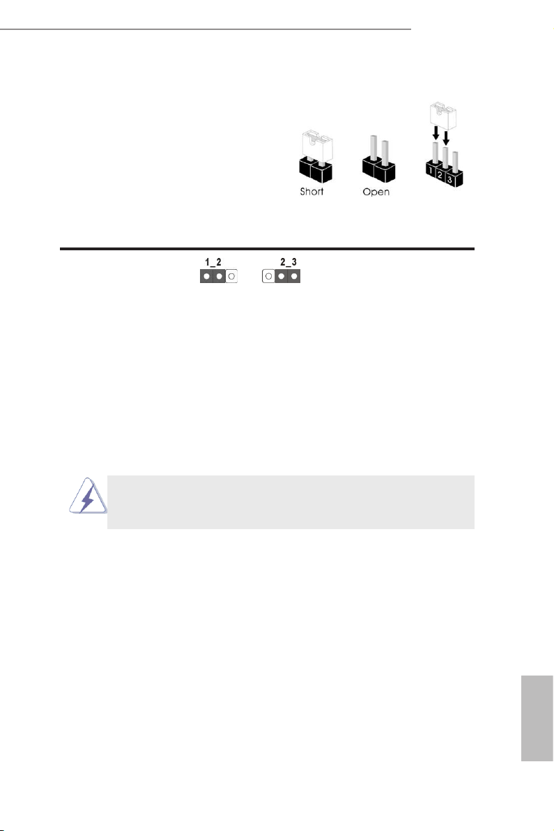
2.5 Jumpers Setup
The illustration sh ow s how jumpers a re
setup. When the jumper cap is placed on
pins, the jumper is “Short”. If no jumper cap
is placed on pins, the jumper is “Open”. The
illus tration shows a 3-pi n jump er whos e
pin1 and pin2 are “Short” when jumper cap
is placed on these 2 pins.
Jumper Setting Description
Clear CMOS Jumper
(CLRCMOS1)
(see p.6, No. 16)
Note: CLRCMOS1 allows you to clear the data in CMOS. To clear and reset the
system parameters to default setup, please turn off the computer and unplug
the power cord from the power supply. After waiting for 15 seconds, use a
jumper cap to short pin2 and pin3 on CLRCMOS1 for 5 seconds. However,
please do not clear the CMOS right after you update the BIOS. If you need
to clear the CMOS when you just nish updating the BIOS, you must boot
up the system rst, and then shut it down before you do the clear-CMOS ac-
tion. Please be noted that the password, date, time, user default prole, 1394
GUID and MAC address will be cleared only if the CMOS battery is removed.
Clear CMOSDefault
If you clear the CMOS, the case open may be detected. Please adjust the
BIOS option “Clear Status” to clear the record of previous chassis intrusion
status.
English
15
2.6 Onboard Headers and Connectors
Onboard headers and connectors are NOT jumpers. Do NOT place
jumper caps over these headers and connectors. Placing jumper caps
over the headers and connectors will cause permanent damage of the
motherboard!
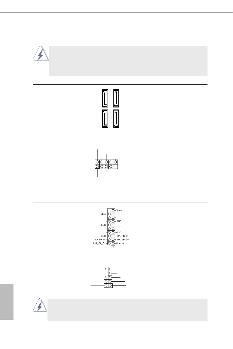
Serial ATA3 Connectors These four Serial ATA3
(SATA_1: see p.6, No. 10)
(SATA_2: see p.6, No. 7)
(SATA_3: see p.6, No. 9)
(SATA_4: see p.6, No. 
6.0 Gb/s data transfer rate.
(SATA3) connectors support
SATA_2
SATA data cables for internal
SATA_4
storage devices. The current
SATA3 interface allows up to
SATA_1
SATA_3
English
USB 2.0 Headers Besides four default USB 2.0
(9-pin USB_7_8)
(see p.6 No. 14)
ports on the I/O panel, there
are two USB 2.0 headers on
this motherboard. Each USB 2.0
header can support two USB
2.0 ports.
(9-pin USB_9_10)
(see p.6 No. 13)
Flexible USB 2.0 Header This Flexible USB 2.0 header
(19-pin USB_11_12)
(see p.6 No. 6)
allows users to connect a front
USB 3.0 panel, and support two
USB ports with 2.0/1.1 data
1
USB _PWR
P-
P+
GND
DUM MY
GND
P+
P-
NC
NC
NC
NC
NC
NC
NC
NC
rate.
Front Panel Audio Header This is an interface for the front
PRE SENC E#
MIC _RET
OUT _RET
GN D
(9-pin HD_AUDIO1)
(see p.6 No. 20)
panel audio cable that allows
convenient connection and
control of audio devices.
1. High Denition Audio supports Jack Sensing, but the panel wire on
the chassis must support HDA to function correctly. Please follow the
instruction in our manual and chassis manual to install your system.
OUT 2_L
J_S ENS E
OUT 2_R
MIC 2_R
MIC 2_L
1
16
Loading…
Manuals.eu
- Manuals.eu
- ASRock
- Computers & Peripherals
- Mainboards
- FM2A68M-DG3+
- User Manual
×
1
2
3
4
5
6
7
8
9
10
11
12
13
14
15
16
17
18
19
20
21
22
23
24
25
26
27
28
29
30
31
32
33
34
35
36
37
38
39
40
41
42
43
44
45
46
47
48
49
50
51
52
53
54
55
56
57
58
59
60
61
62
63
64
65
⟨
⟩
Copyright © Manuals.eu
Agreement
Privacy Policy
Contact us
FAQ: Types of Manuals and Their Contents
ASROCK FM2A68M-DG3+ Manuals come in various types, each serving a specific purpose to help users effectively operate and maintain their devices. Here are the common types of ASROCK FM2A68M-DG3+ User Guides and the information they typically include:
- User Manuals: Provide comprehensive instructions on how to use the device, including setup, features, and operation. They often include troubleshooting tips, safety information, and maintenance guidelines.
- Service Instructions: Designed for technicians and repair professionals, these manuals offer detailed information on diagnosing and repairing issues with the device. They include schematics, parts lists, and step-by-step repair procedures.
- Installation Guides: Focus on the installation process of the device, providing detailed instructions and diagrams for proper setup. They are essential for ensuring the device is installed correctly and safely.
- Maintenance Manuals: Provide guidance on routine maintenance tasks to keep the device in optimal condition. They cover cleaning procedures, part replacements, and regular servicing tips.
- Quick Start Guides: Offer a concise overview of the essential steps needed to get the device up and running quickly. They are ideal for users who need immediate assistance with basic setup and operation.
Each type of ASROCK FM2A68M-DG3+ instruction is designed to address specific needs, ensuring users have the necessary information to use, maintain, and repair their devices effectively.
Related Instructions for ASROCK FM2A68M-DG3+:
2
Z490M-ITX/ac
Manual Manual: ASROCK Z490M-ITX/ac (9AD142, Upd.Tuesday 04-03-2025)
174
1347
283
3
H570 Steel Legend
Manual ASROCK Motherboard Manual (File: asrock-h570-steel-legend-manual-196, 05/03/2025)
196
286
69
5
CONROEXFIRE-ESATA2 — INSTALLATION — 03-2007
Installation manual #6Q6O26: CONROEXFIRE-ESATA2 — INSTALLATION — 03-2007 Motherboard Installation manual
227
274
50
6
775XFIRE-ESATA2 — 02-2006
Operation & user’s manual ASROCK Motherboard Operation & user’s manual (File: asrock-775xfire-esata2-motherboard-57, 27.02.2025)
57
109
17
8
Fatal1ty H87 Performance Series
20
311
60
9
M3A790GMH/128M
Installation manual User Guide: ASROCK M3A790GMH/128M (9852W1, Upd.04.03.2025)
205
364
88
10
AD425PV
Specifications User Manual: ASROCK AD425PV (BZ116Q, Upd.13.10.2024)
6
1118
213
Motherboard Devices by Other Brands:
|
Colorful H310M-M.2 PLUS V20 Operation & User’s Manual Colorful Motherboard Operation & user’s manual (File: colorful-h310m-m2-plus-v20-operation-user-s-manual-12, 12/04/2025) H310M-M.2 PLUS V20 12 Apr 2025 | 12 |
|
|
Biostar M6VCT Operation & User’s Manual M6VCT Operation & user’s manual — 27C5I6 M6VCT 20 Apr 2025 | 81 |
|
|
Sangamo Choice PR3n User Instructions PDF Guide (@OZ466G), Sangamo Choice PR3n Motherboard (Tue 01.2025) Introduction 21 Jan 2025 | 2 |
|
|
Biostar M7TDA Datasheet PDF User Guide (@71Y88E), Biostar M7TDA Motherboard (Wednesday 23-10-2024) 1 23 Oct 2024 | 54 |
Categories:
Baby Swing
Network Card
Transformer
Software
Motherboard
Computer Hardware
ASROCK FM2A68M-DG3+ Motherboard PDF User Guides and Manuals for Free Download: Found (3) Manuals for ASROCK FM2A68M-DG3+ Device Model (Manual , Operation & User’s Manual)
The ASROCK FM2A68M-DG3+ is a notable motherboard designed for PC enthusiasts who are seeking an affordable yet efficient platform. With its micro ATX form factor, this motherboard is particularly well-suited for compact builds without sacrificing essential features. Its design targets users who want to build a robust system for gaming, multimedia, or general computing tasks. With the rise of budget desktop builds, the ASROCK FM2A68M-DG3+ has established itself as a compelling choice for many.
One of the standout features of the FM2A68M-DG3+ is its compatibility with AMD APUs, including the latest A-Series and Athlon series processors. This compatibility is essential for gamers who wish to utilize integrated graphics without investing heavily in discrete graphics cards. The performance of these APUs coupled with the ASROCK motherboard guarantees a satisfactory experience for casual gamers and everyday users alike.
Another key advantage of the ASROCK FM2A68M-DG3+ is its multiple expansion options. It comes equipped with:
- Two PCIe x16 slots, allowing for the installation of graphics cards for enhanced graphical performance.
- One PCIe x1 slot, which can be used for additional sound cards or network cards.
- Four SATA3 connectors that provide ample storage solution options, accommodating SSDs and HDDs for various storage needs.
The FM2A68M-DG3+ also supports up to 32GB of DDR3 RAM, with speeds reaching up to 2400MHz. This memory capability allows users to multitask efficiently and run memory-intensive applications without a hitch. Coupled with ASROCK’s Easy BIOS, users can tweak settings with convenience, optimal for those who enjoy overclocking their systems.
When it comes to connectivity, ASROCK does not disappoint. The FM2A68M-DG3+ features:
- HDMI, DVI-D, and VGA outputs for flexible display connectivity options.
- USB 3.0 ports that speed up file transfers and enhance overall connectivity.
- Gigabit LAN for stable internet connections, crucial for both gaming and streaming purposes.
Furthermore, ASROCK has incorporated solid capacitors that enhance the motherboard’s longevity and reliability, a crucial consideration for avid gamers and users who demand reliability from their components. With these qualities, the ASROCK FM2A68M-DG3+ stands out as a reliable choice for budget-conscious builds.
On the aesthetic front, the FM2A68M-DG3+ features a clean layout with a black and silver color scheme. The overall build quality is commendable, with a sturdy PCB design that instills confidence in its durability.
In conclusion, the ASROCK FM2A68M-DG3+ motherboard is an impressive option for users looking to strike a balance between performance and price. With its excellent support for AMD processors, ample expansion options, robust connectivity features, and reliable build quality, it is undoubtedly a worthwhile investment. If you are looking to assemble a capable desktop without breaking the bank, the ASROCK FM2A68M-DG3+ will meet and perhaps even exceed your expectations.