
Copyright Notice:
No part of this installation guide may be reproduced, transcribed, transmitted, or translated in any language, in any form or by any means, except duplication of documentation
by the purchaser for backup purpose, without written consent of ASRock Inc.
Products and corporate names appearing in this guide may or may not be registered
trademarks or copyrights of their respective companies, and are used only for identication or explanation and to the owners’ benet, without intent to infringe.
Disclaimer:
Specications and information contained in this guide are furnished for informational use
only and subject to change without notice, and should not be constructed as a commitment by ASRock. ASRock assumes no responsibility for any errors or omissions that may
appear in this guide.
With respect to the contents of this guide, ASRock does not provide warranty of any kind,
either expressed or implied, including but not limited to the implied warranties or conditions of merchantability or tness for a particular purpose. In no event shall ASRock, its
directors, ofcers, employees, or agents be liable for any indirect, special, incidental, or
consequential damages (including damages for loss of prots, loss of business, loss of
data, interruption of business and the like), even if ASRock has been advised of the possibility of such damages arising from any defect or error in the guide or product.
This device complies with Part 15 of the FCC Rules. Operation is subject to the following
two conditions:
(1) this device may not cause harmful interference, and
(2) this device must accept any interference received, including interference that
may cause undesired operation.
CALIFORNIA, USA ONLY
The Lithium battery adopted on this motherboard contains Perchlorate, a toxic substance
controlled in Perchlorate Best Management Practices (BMP) regulations passed by the
California Legislature. When you discard the Lithium battery in California, USA, please
follow the related regulations in advance.
“Perchlorate Material-special handling may apply, see
www.dtsc.ca.gov/hazardouswaste/perchlorate”
ASRock Website: http://www.asrock.com
Published June 2011
Copyright©2011 ASRock INC. All rights reserved.
ASRock A75M-HVS Motherboard
English
1
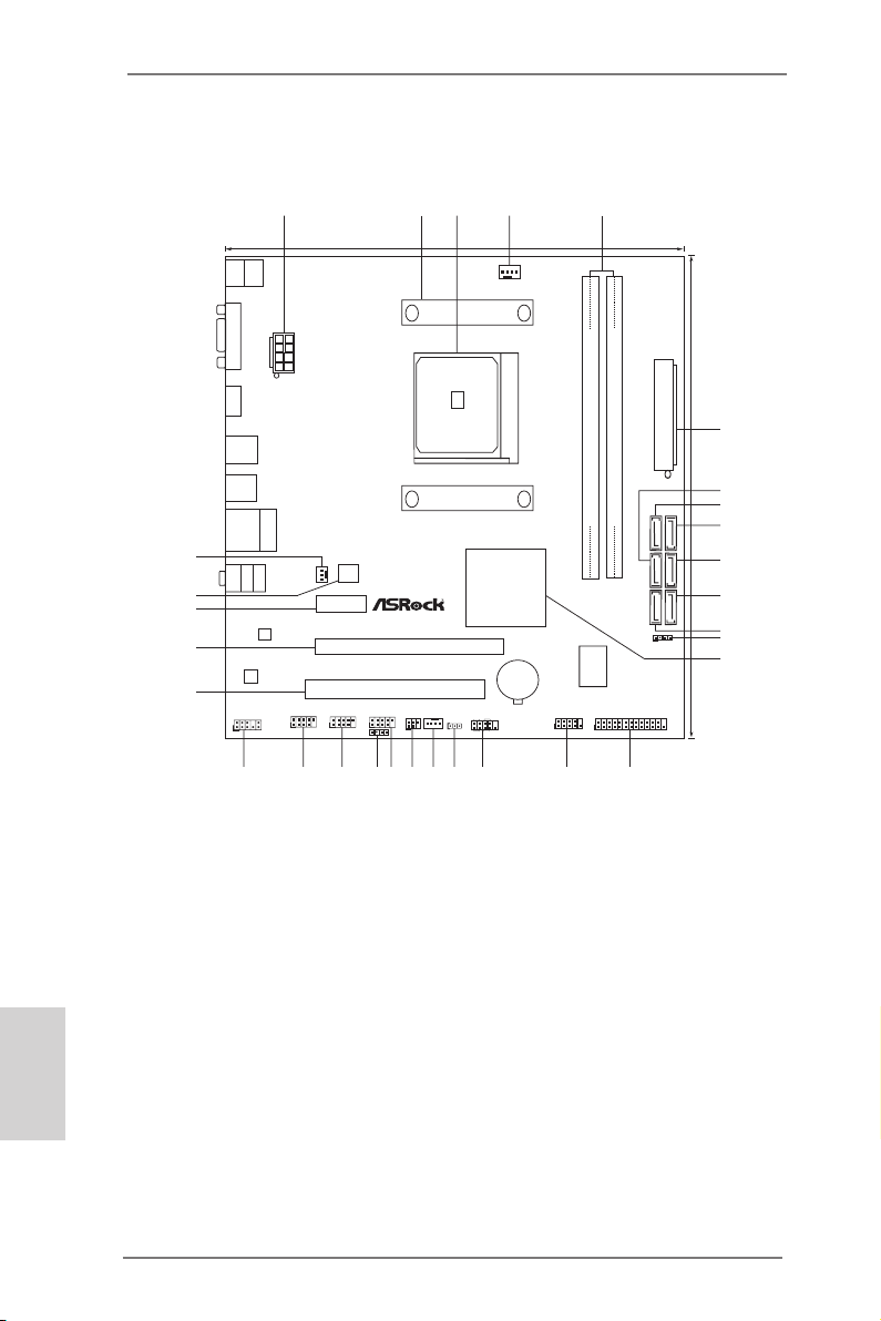
Motherboard Layout
ATXPW R1
AMD
A75 FCH
(Hu dso n-D 3)
Chi pse t
COM1
PCIE 1
PCI 1
LAN
AUDIO
CODEC
1
CLRCMOS1
1
CPU_FAN1
HDLED RESE T
PLED PWRBTN
1
PANEL1
CHA_FAN1
SPEAKER1
1
HD_AUDIO1
1
22. 6cm (8 .9-i n)
21. 6cm (8 .5-i n)
6
7
1
2 4
3
5
8
9
10
11
12
13
14
15
16
17
181920
2122
23
24
25
26
27
28
29
32Mb
BIOS
IR1
1
PCIE 2
FSB 80 0
DDR3 _A1 (6 4 bit, 24 0-pi n modul e)
DDR3 _B1 (6 4 bit, 24 0-pi n modul e)
SATA_2
HDMI1
Top:
LINE IN
Center:
FRONT
Bottom:
MIC IN
RJ-45 LAN
1
1
1
USB6_7
USB8_9
USB10_11
PWR_FAN1
A75M- HV S
ErP /Eu P Rea dy
Des ign e d i n Taip ei
RoH S
DDR 3 24 00+
DX11
USB 2.0
T:U SB0
B: USB1
CIR1
1
SO CK ET FM 1
SATA_1
SATA_4
SATA_3
1
LPT1
ATX12V1
HDM I 1. 4a
PS2
Mouse
PS2
Keyboa rd
VGA1
USB 3.0
T:U SB2
B: USB3
30
SATA_6
SATA_5
USB 3.0
T:U SB4
B: USB5
Dua l Gr aph ics
X
Fas t USB
SATA3 6 Gb/ s
USB 3.0
CMOS
BATTE RY
Supe r
I/O
English
1 ATX 12V Power Connector (ATX12V1) 16 COM Port Header (COM1)
2 CPU Heatsink Retention Module 17 System Panel Header (PANEL1, White)
3 CPU Socket 18 Clear CMOS Jumper (CLRCMOS1)
4 CPU Fan Connector (CPU_FAN1) 19 Chassis Fan Connector (CHA_FAN1)
5 2 x 240-pin DDR3 DIMM Slots 20 Infrared Module Header (IR1)
(Dual Channel: DDR3_A1, DDR3_B1; Blue) 21 USB 2.0 Header (USB6_7, Blue)
6 ATX Power Connector (ATXPWR1) 22 Consumer Infrared Module Header (CIR1)
7 SATA3 Connector (SATA_3, White) 23 USB 2.0 Header (USB8_9, Blue)
8 SATA3 Connector (SATA_5, White) 24 USB 2.0 Header (USB10_11, Blue)
9 SATA3 Connector (SATA_6, White) 25 Front Panel Audio Header (HD_AUDIO1, White)
10 SATA3 Connector (SATA_4, White) 26 PCI Slot (PCI1)
11 SATA3 Connector (SATA_2, White) 27 PCI Express 2.0 x16 Slot (PCIE2; Blue)
12 SATA3 Connector (SATA_1, White) 28 PCI Express 2.0 x1 Slot (PCIE1; White)
13 Chassis Speaker Header (SPEAKER 1, White) 29 SPI Flash Memory (32Mb)
2
14 Southbridge Controller 30 Power Fan Connector (PWR_FAN1)
15 Print Port Header (LPT1, White)
ASRock A75M-HVS Motherboard
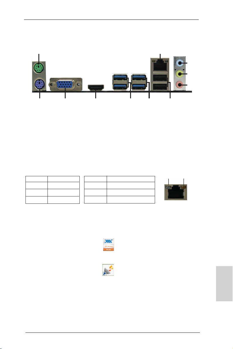
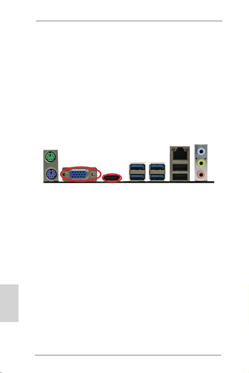
I/O Panel
1
2
3
4
5
1011
1 PS/2 Mouse Port (Green) 7 USB 3.0 Ports (USB45)
* 2 LAN RJ-45 Port 8 USB 3.0 Ports (USB23)
3 Line In (Light Blue) 9 HDMI Port
** 4 Front Speaker (Lime) 10 D-Sub Port
5 Microphone (Pink) 11 PS/2 Keyboard Port (Purple)
*** 6 USB 2.0 Ports (USB01)
* There are two LED next to the LAN port. Please refer to the table below for the LAN port LED
indications.
Activity/Link LED SPEED LED
Status Description Status Description
LAN Port LED Indications
9
8
7
6
ACT/LINK
LED
SPEED
LED
Off No Link Off 10Mbps connection
Blinking Data Activity Orange 100Mbps connection
On Link Green 1Gbps connection
** To enable Multi-Streaming function, you need to connect a front panel audio cable to the front
panel audio header. After restarting your computer, you will nd “VIA HD Audio Deck” tool on
your system. Please follow below instructions according to the OS you install.
For Windows® XP / XP 64-bit OS:
Please click “VIA HD Audio Deck” icon , and click “Speaker”. Then you are allowed to
LAN Port
select “2 Channel” or “4 Channel”. Click “Power” to save your change.
For Windows® 7 / 7 64-bit / VistaTM / VistaTM 64-bit OS:
Please click “VIA HD Audio Deck” icon , and click “Advanced Options” on the left side
on the bottom. In “Advanced Options” screen, select “Independent Headphone”, and click
“OK” to save your change.
*** It is recommended to install the USB Keyboard/Mouse cable to USB 2.0 ports (USB01)
instead of USB 3.0 ports.
ASRock A75M-HVS Motherboard
English
3
1. Introduction
Thank you for purchasing ASRock A75M-HVS motherboard, a reliable motherboard
produced under ASRock’s consistently stringent quality control. It delivers excellent
performance with robust design conforming to ASRock’s commitment to quality and
endurance.
This Quick Installation Guide contains introduction of the motherboard and step-bystep installation guide. More detailed information of the motherboard can be found
in the user manual presented in the Support CD.
Because the motherboard specications and the BIOS software might be
updated, the content of this manual will be subject to change without notice. In case any modications of this manual occur, the updated version
will be available on ASRock website without further notice. You may nd
the latest VGA cards and CPU support lists on ASRock website as well.
ASRock website http://www.asrock.com
If you require technical support related to this motherboard, please visit
our website for specic information about the model you are using.
www.asrock.com/support/index.asp
1.1 Package Contents
ASRock A75M-HVS Motherboard
(Micro ATX Form Factor: 8.9-in x 8.5-in, 22.6 cm x 21.6 cm)
ASRock A75M-HVS Quick Installation Guide
ASRock A75M-HVS Support CD
2 x Serial ATA (SATA) Data Cables (Optional)
1 x I/O Panel Shield
English
ASRock Reminds You…
To get better performance in Windows® 7 / 7 64-bit / Vista
bit, it is recommended to set the BIOS option in Storage Conguration to
AHCI mode. For the BIOS setup, please refer to the “User Manual” in our
support CD for details.
TM
/ VistaTM 64-
4
ASRock A75M-HVS Motherboard
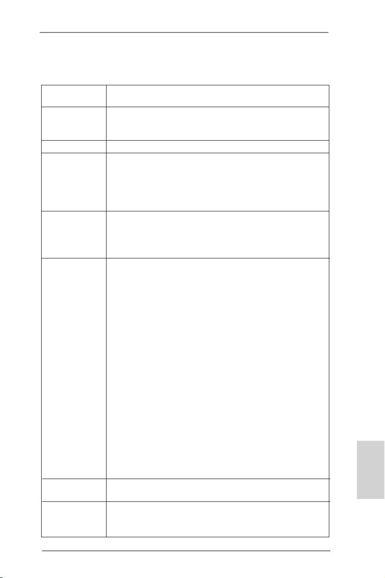
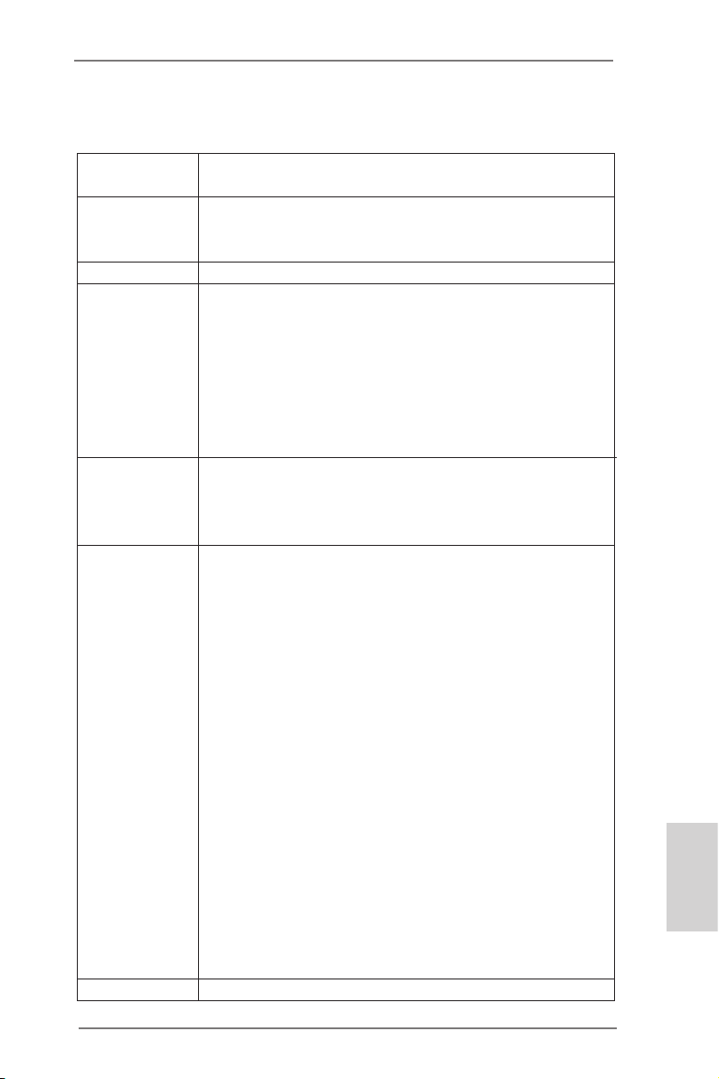
1.2 Specifications
Platform — Micro ATX Form Factor: 8.9-in x 8.5-in, 22.6 cm x 21.6 cm
— Solid Capacitor for CPU power
CPU — Support for Socket FM1 100W processors
— Supports AMD’s Cool ‘n’ QuietTM Technology
— UMI-Link GEN2
Chipset — AMD A75 FCH (Hudson-D3)
Memory — Dual Channel DDR3 Memory Technology (see CAUTION 1)
— 2 x DDR3 DIMM slots
— Support DDR3 2400+(OC)/1866/1600/1333/
1066/800 non-ECC, un-buffered memory (see CAUTION 2)
— Max. capacity of system memory: 16GB (see CAUTION 3)
Expansion Slot — 1 x PCI Express 2.0 x16 slot
— 1 x PCI Express 2.0 x1 slot
— 1 x PCI slot
— Supports AMD Dual Graphics
Graphics — AMD Radeon HD 65XX/64XX graphics
— DirectX 11, Pixel Shader 5.0
— Max. shared memory 512MB (see CAUTION 4)
— Dual VGA Output: support HDMI and D-Sub ports by
independent display controllers
— Supports HDMI 1.4a Technology with max. resolution up to
1920×1200 @ 60Hz
— Supports D-Sub with max. resolution up to 1920×1600 @
60Hz
— Supports Auto Lip Sync, Deep Color (12bpc), xvYCC and
HBR (High Bit Rate Audio) with HDMI (Compliant HDMI
monitor is required) (see CAUTION 5)
— Supports Blu-ray Stereoscopic 3D with HDMI 1.4a
— Supports AMD Steady VideoTM: New video post processing
capability for automatic jutter reduction on home/online
video
— Supports HDCP function with HDMI port
— Supports Full HD 1080p Blu-ray (BD) / HD-DVD playback
with HDMI port
Audio — 5.1 CH HD Audio (VIA® VT1705 Audio Codec)
— Supports THX TruStudioTM
LAN — PCIE x1 Gigabit LAN 10/100/1000 Mb/s
— Realtek RTL8111E
— Supports Wake-On-LAN
English
ASRock A75M-HVS Motherboard
5
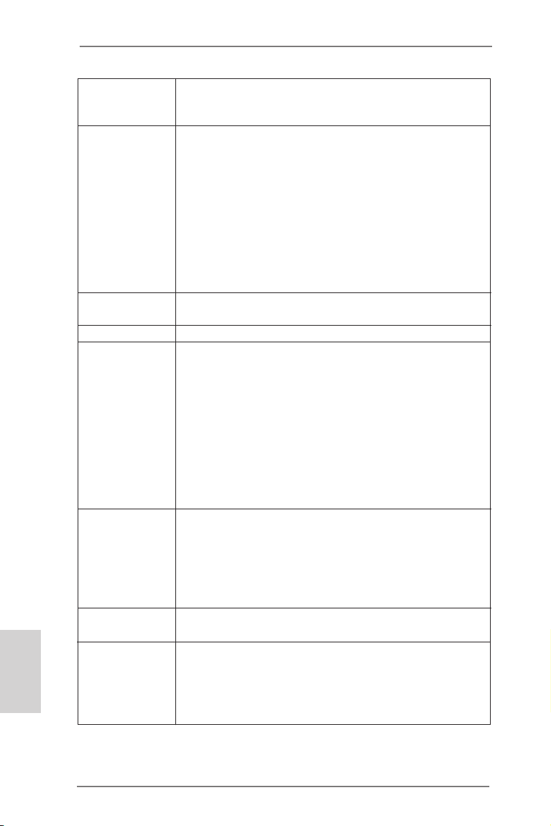
English
— Supports LAN Cable Detection
— Supports Energy Efcient Ethernet 802.3az
— Supports PXE
Rear Panel I/O I/O Panel
— 1 x PS/2 Mouse Port
— 1 x PS/2 Keyboard Port
— 1 x D-Sub Port
— 1 x HDMI Port
— 2 x Ready-to-Use USB 2.0 Ports
— 4 x Ready-to-Use USB 3.0 Ports
— 1 x RJ-45 LAN Port with LED (ACT/LINK LED and SPEED
LED)
— HD Audio Jack: Line in/Front Speaker/Microphone
SATA3 — 6 x SATA3 6.0 Gb/s connectors, support RAID (RAID 0,
RAID 1 and RAID 10), NCQ, AHCI and “Hot Plug” functions
USB 3.0 — 4 x USB 3.0 ports, support USB 1.0/2.0/3.0 up to 5Gb/s
Connector — 6 x SATA3 6.0Gb/s connectors
— 1 x IR header
— 1 x CIR header
— 1 x Print port header
— 1 x COM port header
— CPU/Chassis/Power FAN connector
— 24 pin ATX power connector
— 8 pin 12V power connector
— Front panel audio connector
— 3 x USB 2.0 headers (support 6 USB 2.0 ports)
BIOS Feature — 32Mb AMI UEFI Legal BIOS with GUI support
— Supports “Plug and Play”
— ACPI 1.1 Compliance Wake Up Events
— Supports jumperfree
— SMBIOS 2.3.1 Support
— DRAM, VDDP, SB Voltage Multi-adjustment
Support CD — Drivers, Utilities, AntiVirus Software (Trial Version),
CyberLink MediaEspresso 6.5 Trial
Unique Feature — ASRock Extreme Tuning Utility (AXTU) (see CAUTION 6)
— ASRock Instant Boot
— ASRock Instant Flash (see CAUTION 7)
— ASRock APP Charger (see CAUTION 8)
— ASRock XFast USB (see CAUTION 9)
6
ASRock A75M-HVS Motherboard
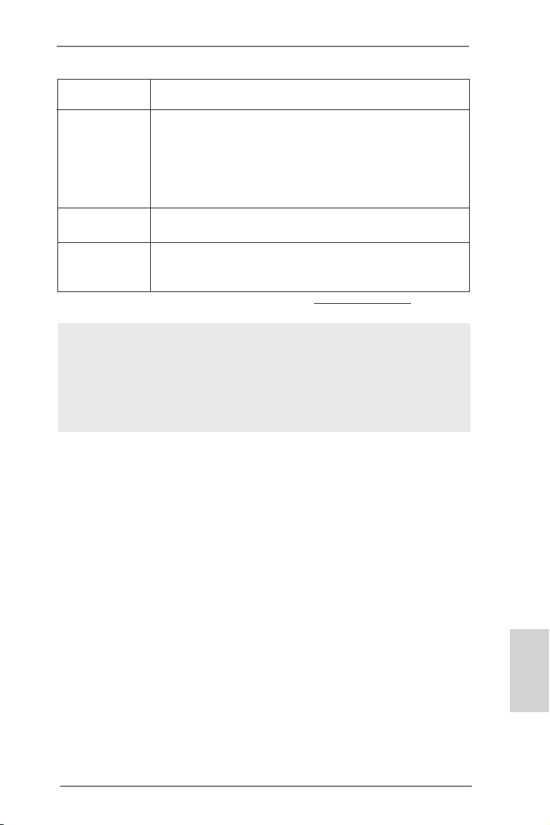
— Hybrid Booster:
— ASRock U-COP (see CAUTION 10)
Hardware — CPU Temperature Sensing
Monitor — Chassis Temperature Sensing
— CPU/Chassis/Power Fan Tachometer
— CPU/Chassis Quiet Fan
— CPU/Chassis Fan Multi-Speed Control
— Voltage Monitoring: +12V, +5V, +3.3V, Vcore
OS — Microsoft® Windows® 7 / 7 64-bit / Vista
TM
/ VistaTM 64-bit / XP
SP3 / XP 64-bit compliant
Certications — FCC, CE, WHQL
— ErP/EuP Ready (ErP/EuP ready power supply is required)
(see CAUTION 11)
* For detailed product information, please visit our website: http://www.asrock.com
WARNING
Please realize that there is a certain risk involved with overclocking, including adjusting the
setting in the BIOS, applying Untied Overclocking Technology, or using the third-party overclocking tools. Overclocking may affect your system stability, or even cause damage to the
components and devices of your system. It should be done at your own risk and expense.
We are not responsible for possible damage caused by overclocking.
ASRock A75M-HVS Motherboard
English
7

English
CAUTION!
1. This motherboard supports Dual Channel Memory Technology. Before
you implement Dual Channel Memory Technology, make sure to read the
installation guide of memory modules on page 12 for proper installation.
2. Whether 2400/1866/1600MHz memory speed is supported depends on
the CPU you adopt. If you want to adopt DDR3 2400/1866/1600 memory
module on this motherboard, please refer to the memory support list on
our website for the compatible memory modules.
ASRock website http://www.asrock.com
3. Due to the operating system limitation, the actual memory size may be
less than 4GB for the reservation for system usage under Windows® 7 /
VistaTM / XP. For Windows® 64-bit OS with 64-bit CPU, there is no such
limitation.
4. The maximum shared memory size is dened by the chipset vendor and
is subject to change. Please check AMD website for the latest information.
5. xvYCC and Deep Color are only supported under Windows® 7 64-bit /
7. Deep Color mode will be enabled only if the display supports 12bpc
in EDID. HBR is supported under Windows® 7 64-bit / 7 / VistaTM 64-bit /
VistaTM.
6. ASRock Extreme Tuning Utility (AXTU) is an all-in-one tool to ne-tune
different system functions in a user-friendly interface, which is including
Hardware Monitor, Fan Control and IES. In Hardware Monitor, it shows
the major readings of your system. In Fan Control, it shows the fan speed
and temperature for you to adjust. In IES (Intelligent Energy Saver), the
voltage regulator can reduce the number of output phases to improve
efficiency when the CPU cores are idle without sacrificing computing
performance. Please visit our website for the operation procedures of
ASRock Extreme Tuning Utility (AXTU).
ASRock website: http://www.asrock.com
7. ASRock Instant Flash is a BIOS ash utility embedded in Flash ROM.
This convenient BIOS update tool allows you to update system BIOS
without entering operating systems rst like MS-DOS or Windows®. With
this utility, you can press <F6> key during the POST or press <F2> key to
BIOS setup menu to access ASRock Instant Flash. Just launch this tool
and save the new BIOS le to your USB ash drive, oppy disk or hard
drive, then you can update your BIOS only in a few clicks without preparing an additional oppy diskette or other complicated ash utility. Please
be noted that the USB ash drive or hard drive must use FAT32/16/12 le
system.
8
ASRock A75M-HVS Motherboard

8. If you desire a faster, less restricted way of charging your Apple devices,
such as iPhone/iPod/iPad Touch, ASRock has prepared a wonderful solution for you — ASRock APP Charger. Simply installing the APP Charger
driver, it makes your iPhone charged much quickly from your computer
and up to 40% faster than before. ASRock APP Charger allows you to
quickly charge many Apple devices simultaneously and even supports
continuous charging when your PC enters into Standby mode (S1), Suspend to RAM (S3), hibernation mode (S4) or power off (S5). With APP
Charger driver installed, you can easily enjoy the marvelous charging
experience than ever.
ASRock website: http://www.asrock.com/Feature/AppCharger/index.asp
9. ASRock XFast USB can boost USB storage device performance. The
performance may depend on the property of the device.
10. While CPU overheat is detected, the system will automatically shutdown.
Before you resume the system, please check if the CPU fan on the motherboard functions properly and unplug the power cord, then plug it back
again. To improve heat dissipation, remember to spray thermal grease
between the CPU and the heatsink when you install the PC system.
11. EuP, stands for Energy Using Product, was a provision regulated by European Union to dene the power consumption for the completed system.
According to EuP, the total AC power of the completed system shall be
under 1.00W in off mode condition. To meet EuP standard, an EuP ready
motherboard and an EuP ready power supply are required. According to
Intel’s suggestion, the EuP ready power supply must meet the standard
of 5v standby power efciency is higher than 50% under 100 mA current
consumption. For EuP ready power supply selection, we recommend you
checking with the power supply manufacturer for more details.
ASRock A75M-HVS Motherboard
English
9
2. Installation
This is a Micro ATX form factor (8.9-in x 8.5-in, 22.6 cm x 21.6 cm) motherboard.
Before you install the motherboard, study the conguration of your chassis to ensure
that the motherboard ts into it.
Pre-installation Precautions
Take note of the following precautions before you install motherboard
components or change any motherboard settings.
Before you install or remove any component, ensure that the
power is switched off or the power cord is detached from the
power supply. Failure to do so may cause severe damage to the
motherboard, peripherals, and/or components.
1. Unplug the power cord from the wall socket before touching any
component.
2. To avoid damaging the motherboard components due to static electricity, NEVER place your motherboard directly on the carpet or the
like. Also remember to use a grounded wrist strap or touch a safety
grounded object before you handle components.
3. Hold components by the edges and do not touch the ICs.
4. Whenever you uninstall any component, place it on a grounded antistatic pad or in the bag that comes with the component.
5. When placing screws into the screw holes to secure the motherboard to the chassis, please do not over-tighten the screws! Doing
so may damage the motherboard.
English
10
ASRock A75M-HVS Motherboard
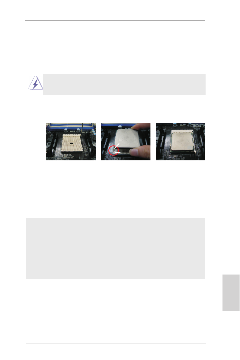
2.1 CPU Installation
Step 1. Unlock the socket by lifting the lever up to a 90
o
angle.
Step 2. Position the CPU directly above the socket such that the CPU corner with
the golden triangle matches the socket corner with a small triangle.
Step 3. Carefully insert the CPU into the socket until it ts in place.
The CPU ts only in one correct orientation. DO NOT force the CPU
into the socket to avoid bending of the pins.
Step 4. When the CPU is in place, press it rmly on the socket while you push
down the socket lever to secure the CPU. The lever clicks on the side tab
to indicate that it is locked.
Lever 90° Up
CPU Golden Triangle
Socket Corner Small
Triangle
STEP 1:
Lift Up The Socket Lever
STEP 2 / STEP 3:
Match The CPU Golden Triangle
To The Socket Corner Small
Triangle
STEP 4:
Push Down And Lock
The Socket Lever
2.2 Installation of CPU Fan and Heatsink
After you install the CPU into this motherboard, it is necessary to install a
larger heatsink and cooling fan to dissipate heat. You also need to spray
thermal grease between the CPU and the heatsink to improve heat dissipation. Make sure that the CPU and the heatsink are securely fastened
and in good contact with each other. Then connect the CPU fan to the
CPU FAN connector (CPU_FAN1, see Page 2, No. 4). For proper installation, please kindly refer to the instruction manuals of the CPU fan and
the heatsink.
English
ASRock A75M-HVS Motherboard
11
2.3 Installation of Memory Modules (DIMM)
This motherboard provides two 240-pin DDR3 (Double Data Rate 3) DIMM slots,
and supports Dual Channel Memory Technology. For dual channel configuration,
you always need to install two identical (the same brand, speed, size and chiptype) memory modules in the DDR3 DIMM slots to activate Dual Channel Memory
Technology. Otherwise, it will operate at single channel mode.
1. It is not allowed to install a DDR or DDR2 memory module into
DDR3 slot;otherwise, this motherboard and DIMM may be
damaged.
2. If you install only one memory module or two non-identical
memory modules, it is unable to activate the Dual Channel
Memory Technology.
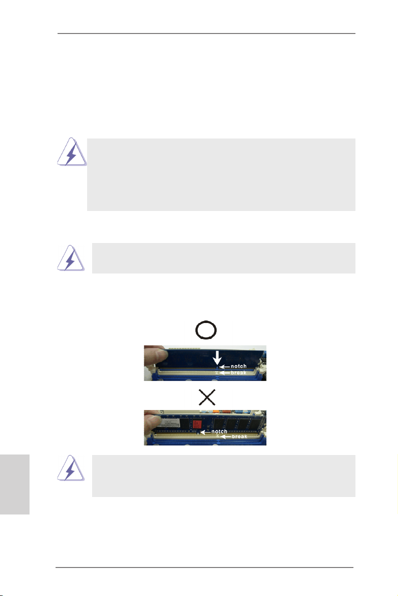
Installing a DIMM
Please make sure to disconnect power supply before adding or
removing DIMMs or the system components.
Step 1. Unlock a DIMM slot by pressing the retaining clips outward.
Step 2. Align a DIMM on the slot such that the notch on the DIMM matches the
break on the slot.
English
damage to the motherboard and the DIMM if you force the DIMM into the slot
at incorrect orientation.
The DIMM only ts in one correct orientation. It will cause permanent
Step 3. Firmly insert the DIMM into the slot until the retaining clips at both ends
fully snap back in place and the DIMM is properly seated.
12
ASRock A75M-HVS Motherboard

2.4 Expansion Slots (PCI and PCI Express Slots)
There are 1 PCI slot and 2 PCI Express slots on this motherboard.
PCI Slot: PCI slot is used to install expansion cards that have the 32-bit PCI
interface.
PCIE Slots:
PCIE1 (PCIE x1 slot; White) is used for PCI Express cards with x1 lane
width cards, such as Gigabit LAN card and SATA2 card.
PCIE2 (PCIE x16 slot; Blue) is used for PCI Express x16 lane width
graphics cards.
Installing an expansion card
Step 1. Before installing the expansion card, please make sure that the power
supply is switched off or the power cord is unplugged. Please read the
documentation of the expansion card and make necessary hardware
settings for the card before you start the installation.
Step 2. Remove the system unit cover (if your motherboard is already installed
in a chassis).
Step 3. Remove the bracket facing the slot that you intend to use. Keep the
screws for later use.
Step 4. Align the card connector with the slot and press rmly until the card is
completely seated on the slot.
Step 5. Fasten the card to the chassis with screws.
Step 6. Replace the system cover.
ASRock A75M-HVS Motherboard
English
13
2.5 AMD Dual Graphics Operation Guide
This motherboard supports AMD Dual Graphics feature. AMD Dual Graphics brings
multi-GPU performance capabilities by enabling an AMD A75 FCH (Hudson-D3)
integrated graphics processor and a discrete graphics processor to operate
simultaneously with combined output to a single display for blisteringly-fast frame
rates. Currently, AMD Dual Graphics Technology is only supported with Windows® 7
OS, and is not available with Windows® VistaTM / XP OS.
What does an AMD Dual Graphics system include?
An AMD Dual Graphics system includes an AMD Radeon HD 65XX/64XX graphics
processor and a motherboard based on an AMD A75 FCH (Hudson-D3) integrated
chipset, all operating in a Windows® 7 environment. Please refer to below PCI
Express graphics card support list for AMD Dual Graphics. For the future update of
more compatible PCI Express graphics cards, please visit AMD website for further
information.
Chipset Model Driver
AMD RADEON HD6670 ASUS DIS-PCIE2.1-ASUS-HDMI-EAH6670-DI-1GD3/1G-DDR3 8.86
AMD RADEON HD6570 MSI DIS-PCIE2.1-MSI-HDMI-R6570-MD1GD3-LP/1G-DDR3 8.86
AMD RADEON HD6450 MSI DIS-PCIE2.1-MSI-HDMI-R6450-MD1GD3-LP/1G-DDR3 8.86
Enjoy the benefit of AMD Dual Graphics
Step 1. Please keep the default UEFI setting of “Dual Graphics“ option on [Auto].
Step 2. Install one AMD RADEON HD6670 / 6570 / 6450 PCI Express graphics
card to PCIE2 slot (blue).
Step 3. Connect the monitor cable to the onboard VGA port. Please be noted that
the current VGA driver / VBIOS can allow Dual Graphics output from onboard display only. For any future update, please refer to our website for
further information.
Step 4. Boot into OS. Please remove the AMD driver if you have any VGA driver
installed in your system.
Step 5. Install the onboard VGA driver from our support CD to your system for
both the onboard VGA and the discrete graphics card.
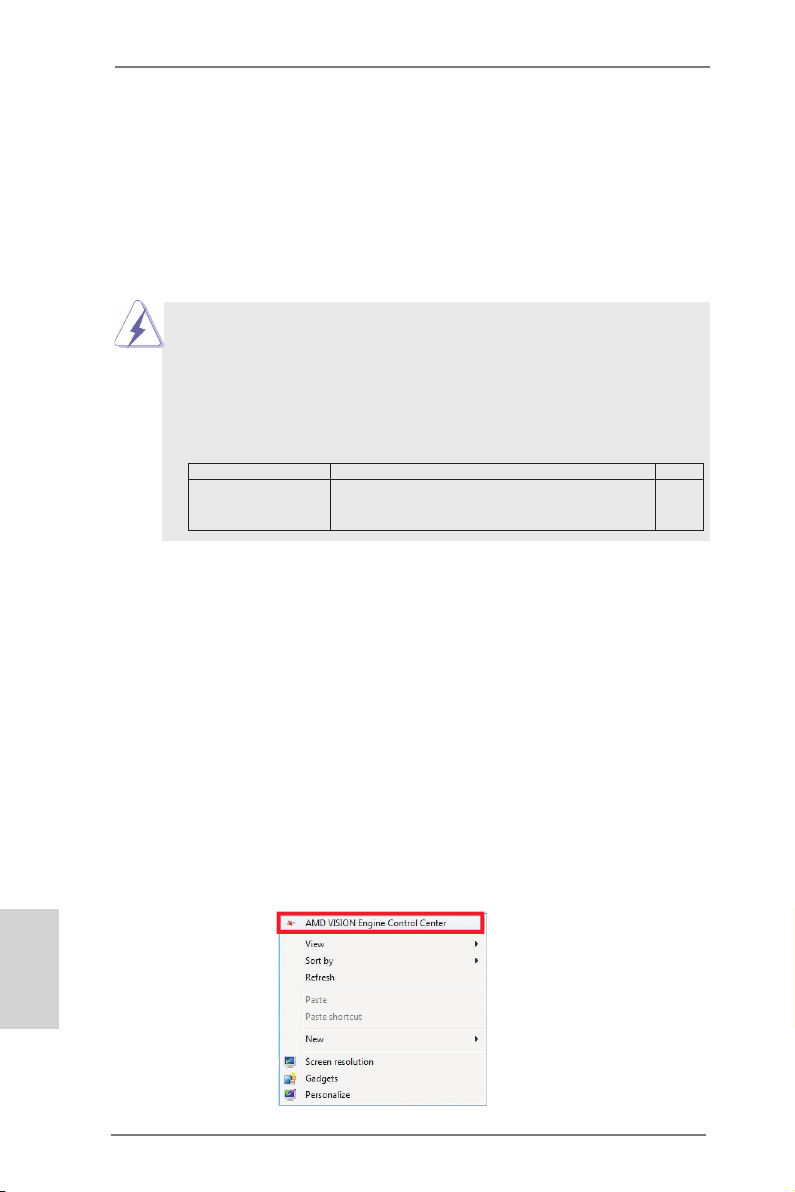
Step 6. Restart your computer. Right-click the desktop. Click “AMD VISION
Engine Control Center” to enter AMD VISION Engine Control Center.
English
14
ASRock A75M-HVS Motherboard
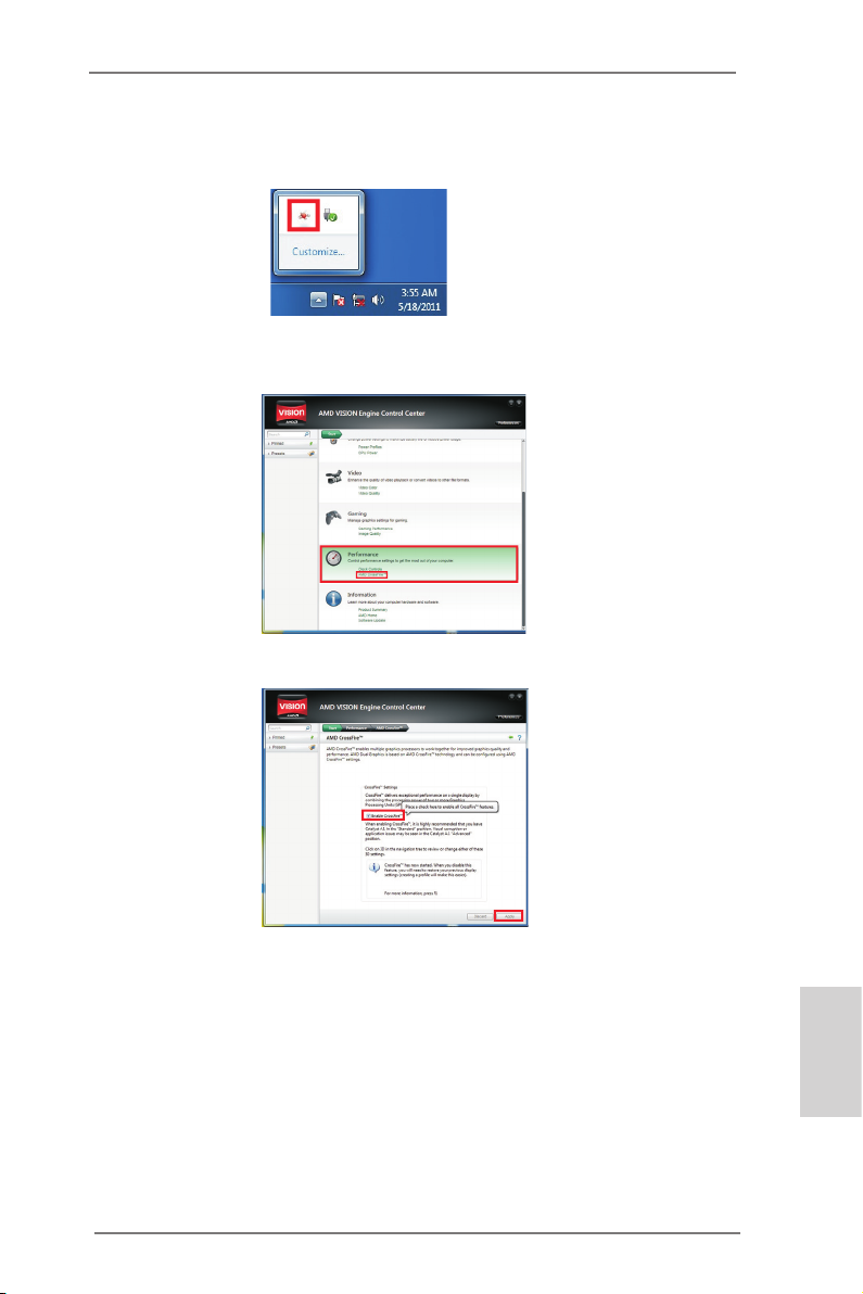
Step 7. You can also click “AMD VISION Engine Control Center” on your
Windows® taskbar to enter AMD VISION Engine Control Center.
AMD VISION Engine Control Center
Step 8. In AMD VISION Engine Control Center, please choose “Performance”.
Click “AMD CrossFireTM”.
Step 9. Click “Enable CrossFireTM” and click “Apply“ to save your change.
Step 10. Reboot your system. Then you can freely enjoy the benet of Dual
Graphics feature.
* Dual Graphics appearing here is a registered trademark of AMD Technologies Inc., and is
used only for identication or explanation and to the owners’ benet, without intent to infringe.
* For further information of AMD Dual Graphics technology, please check AMD website for up
dates and details.
ASRock A75M-HVS Motherboard
English
15
2.6 Dual Monitor and Surround Display Features
Dual Monitor Feature
This motherboard supports dual monitor feature. With the internal VGA output support (D-Sub and HDMI), you can easily enjoy the benets of dual monitor feature
without installing any add-on VGA card to this motherboard. This motherboard also
provides independent display controllers for D-Sub and HDMI to support dual VGA
output so that D-sub and HDMI can drive same or different display contents.
To enable dual monitor feature, please follow the below steps:
1. Connect D-Sub monitor cable to D-Sub port on the I/O panel, or connect
HDMI monitor cable to HDMI port on the I/O panel.
English
VGA/D-Sub port
2. If you have installed onboard VGA driver from our support CD to your system
already, you can freely enjoy the benets of dual monitor function after your
system boots. If you haven’t installed onboard VGA driver yet, please install
onboard VGA driver from our support CD to your system and restart your
computer.
HDMI port
16
ASRock A75M-HVS Motherboard

Surround Display Feature
This motherboard supports surround display upgrade. With the internal VGA output
support (D-Sub and HDMI) and external add-on PCI Express VGA cards, you can
easily enjoy the benets of surround display feature.
Please refer to the following steps to set up a surround display environment:
1. Install the PCI Express VGA cards on PCIE2 slot. Please refer to page 13 for
proper expansion card installation procedures for details.
2. Connect D-Sub monitor cable to D-Sub port on the I/O panel, or connect
HDMI monitor cable to HDMI port on the I/O panel. Then connect other monitor
cables to the corresponding connectors of the add-on PCI Express VGA cards on
PCIE2 slot.
3. Boot your system. Press <F2> or <Del> to enter UEFI setup. Enter “Share
Memory” option to adjust the memory capability to [32MB], [64MB], [128MB],
[256MB] or [512MB] to enable the function of D-sub. Please make sure that
the value you select is less than the total capability of the system memory. If you
do not adjust the UEFI setup, the default value of “Share Memory”, [Auto], will
disable D-Sub function when the add-on VGA card is inserted to this
motherboard.
4. Install the onboard VGA driver and the add-on PCI Express VGA card driver to
your system. If you have installed the drivers already, there is no need to install
them again.
5. Set up a multi-monitor display.
For Windows® XP / XP 64-bit OS:
Right click the desktop, choose “Properties”, and select the “Settings” tab
so that you can adjust the parameters of the multi-monitor according to
the steps below.
A. Click the “Identify” button to display a large number on each monitor.
B. Right-click the display icon in the Display Properties dialog that you
wish to be your primary monitor, and then select “Primary”. When
you use multiple monitors with your card, one monitor will always be
Primary, and all additional monitors will be designated as Secondary.
C. Select the display icon identied by the number 2.
D. Click “Extend my Windows desktop onto this monitor”.
E. Right-click the display icon and select “Attached”, if necessary.
F. Set the “Screen Resolution” and “Color Quality” as appropriate for the
second monitor. Click “Apply” or “OK” to apply these new values.
G. Repeat steps C through E for the diaplay icon identied by the number
one to four.
English
ASRock A75M-HVS Motherboard
17
For Windows® 7 / 7 64-bit / VistaTM / VistaTM 64-bit OS:
Right click the desktop, choose “Personalize”, and select the “Display
Settings” tab so that you can adjust the parameters of the multi-monitor
according to the steps below.
A. Click the number ”2” icon.
B. Click the items “This is my main monitor” and “Extend the desktop onto
this monitor”.
C. Click “OK” to save your change.
D. Repeat steps A through C for the display icon identied by the number
three to four.
6. Use Surround Display. Click and drag the display icons to positions representing
the physical setup of your monitors that you would like to use. The placement
of display icons determines how you move items from one monitor to another.
HDCP Function
HDCP function is supported on this motherboard. To use HDCP
function with this motherboard, you need to adopt the monitor
that supports HDCP function as well. Therefore, you can enjoy
the superior display quality with high-denition HDCP
encryption contents. Please refer to below instruction for more
details about HDCP function.
What is HDCP?
HDCP stands for High-Bandwidth Digital Content Protection,
a specication developed by Intel® for protecting digital
entertainment content that uses the DVI interface. HDCP is a
copy protection scheme to eliminate the possibility of
intercepting digital data midstream between the video source,
or transmitter — such as a computer, DVD player or set-top box and the digital display, or receiver — such as a monitor, television
or projector. In other words, HDCP specication is designed to
protect the integrity of content as it is being transmitted.
English
Products compatible with the HDCP scheme such as DVD
players, satellite and cable HDTV set-top-boxes, as well as few
entertainment PCs requires a secure connection to a compliant
display. Due to the increase in manufacturers employing HDCP
in their equipment, it is highly recommended that the HDTV or
LCD monitor you purchase is compatible.
18
ASRock A75M-HVS Motherboard
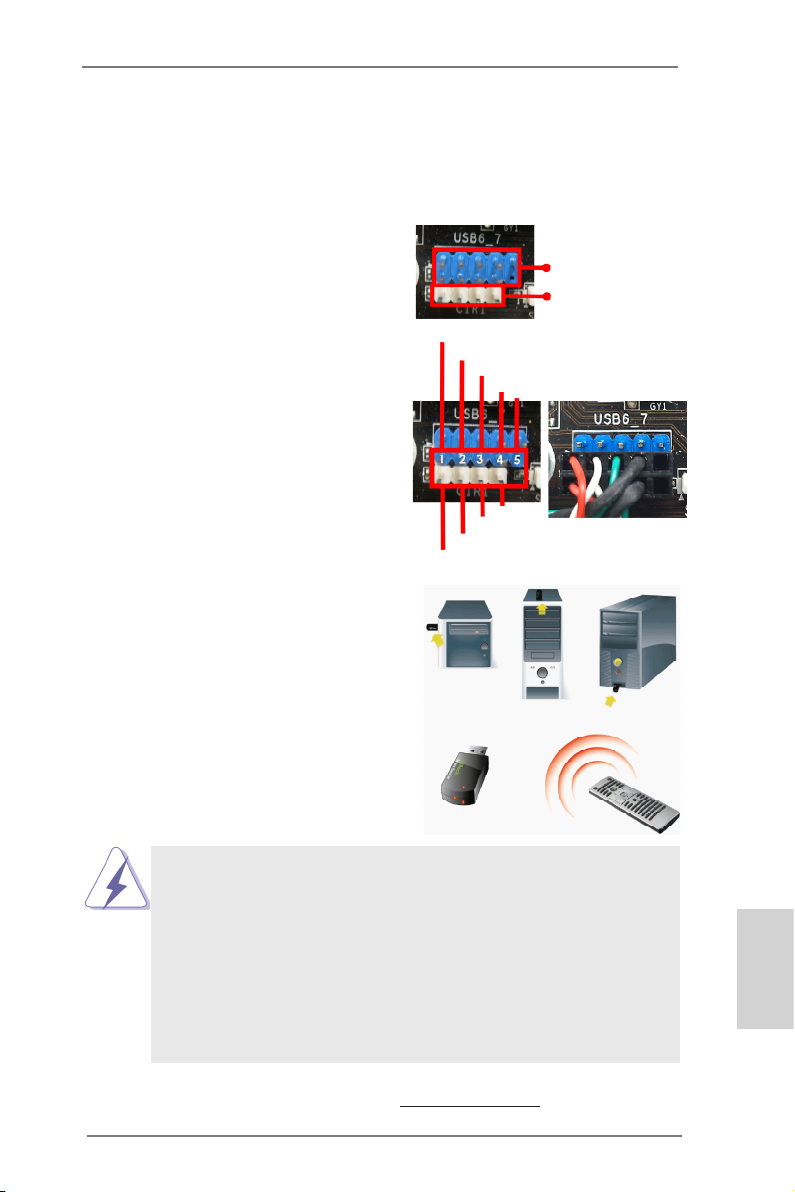
2.7 ASRock Smart Remote Installation Guide
ASRock Smart Remote is only used for ASRock motherboard with CIR header.
Please refer to below procedures for the quick installation and usage of ASRock
Smart Remote.
Step1. Find the CIR header located next
to the USB 2.0 header on ASRock
motherboard.
Step2. Connect the front USB cable to the
USB 2.0 header (as below, pin 1-5)
and the CIR header. Please make
sure the wire assignments and the
pin assignments are matched
correctly.
Step3. Install Multi-Angle CIR Receiver to
the front USB port. If Multi-Angle
CIR Receiver cannot successfully
receive the infrared signals from
MCE Remote Controller, please try
to install it to the other front USB
port.
USB_PWR
ATX+5VSB
P-
IRRX
P+
GND
IRTX
USB 2.0 header
(9-pin, blue)
CIR header
(4-pin, white)
DUMMY
GND
3 CIR sensors in different angles
1. Only one of the front USB port can support CIR function. When the
CIR function is enabled, the other port will remain USB function.
2. Multi-Angle CIR Receiver is used for front USB only. Please do not
use the rear USB bracket to connect it on the rear panel. Multi-Angle
CIR Receiver can receive the multi-direction infrared signals (top,
down and front), which is compatible with most of the chassis on the
market.
3. The Multi-Angle CIR Receiver does not support Hot-Plug function.
Please install it before you boot the system.
* ASRock Smart Remote is only supported by some of ASRock motherboards. Please refer to
ASRock website for the motherboard support list: http://www.asrock.com
ASRock A75M-HVS Motherboard
English
19
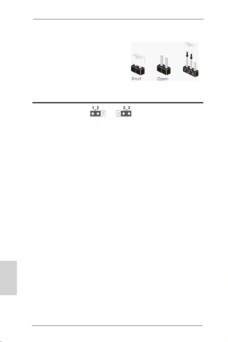
2.8 Jumpers Setup
The illustration shows how jumpers are
setup. When the jumper cap is placed on
pins, the jumper is “Short”. If no jumper cap
is placed on pins, the jumper is “Open”. The
illustration shows a 3-pin jumper whose
pin1 and pin2 are “Short” when jumper cap
is placed on these 2 pins.
Jumper Setting Description
Clear CMOS Jumper
(CLRCMOS1)
(see p.2, No. 18)
Note: CLRCMOS1 allows you to clear the data in CMOS. To clear and reset the
system parameters to default setup, please turn off the computer and unplug
the power cord from the power supply. After waiting for 15 seconds, use a
jumper cap to short pin2 and pin3 on CLRCMOS1 for 5 seconds. However,
please do not clear the CMOS right after you update the BIOS. If you need
to clear the CMOS when you just nish updating the BIOS, you must boot
up the system rst, and then shut it down before you do the clear-CMOS action. Please be noted that the password, date, time, user default prole, 1394
GUID and MAC address will be cleared only if the CMOS battery is removed.
Clear CMOSDefault
English
20
ASRock A75M-HVS Motherboard
2.9 Onboard Headers and Connectors
Onboard headers and connectors are NOT jumpers. Do NOT place
jumper caps over these headers and connectors. Placing jumper caps
over the headers and connectors will cause permanent damage of the
motherboard!
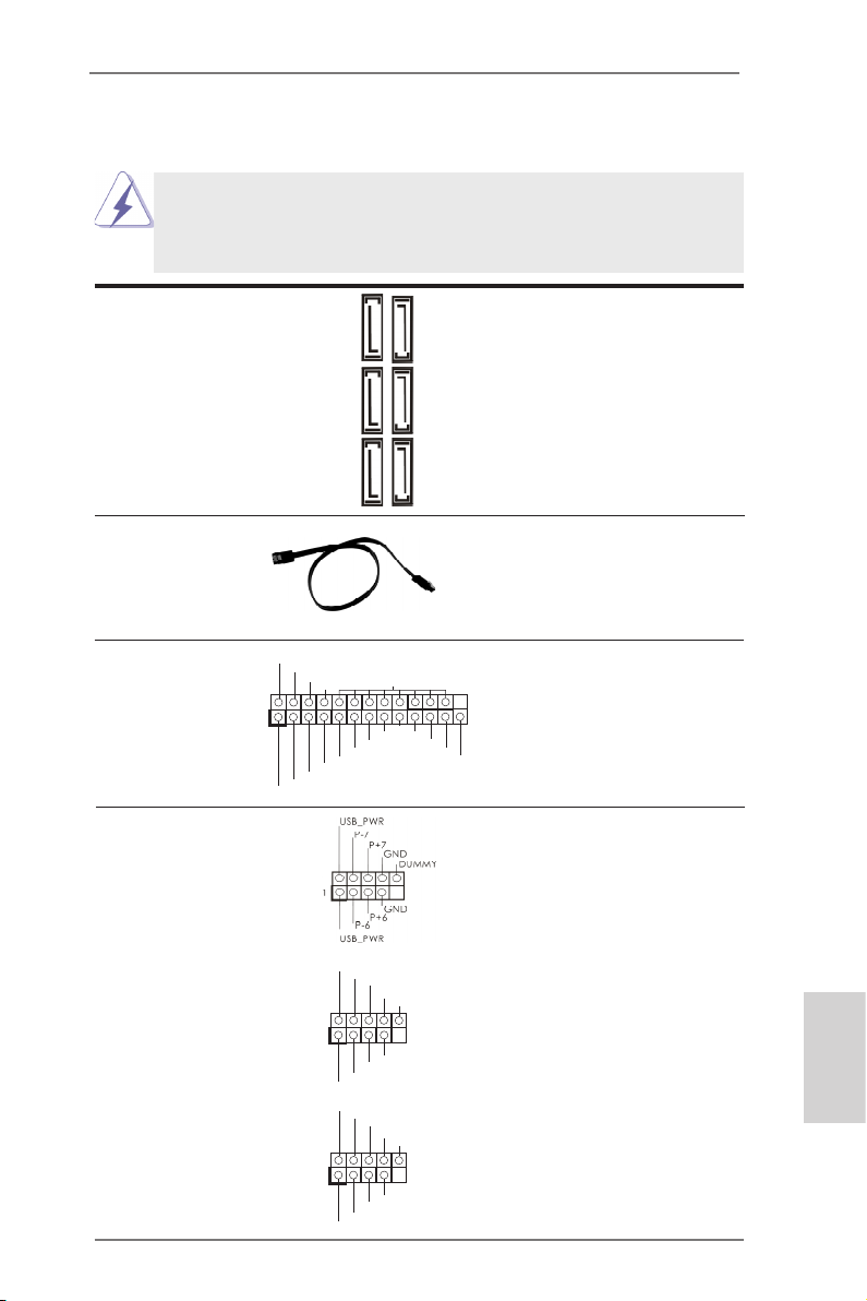
Serial ATA3 Connectors These six Serial ATA3
(SATA_1: see p.2, No. 12)
(SATA_2: see p.2, No. 11)
(SATA_3: see p.2, No. 7)
(SATA_4: see p.2, No. 10)
(SATA_5: see p.2, No. 
(SATA_6: see p.2, No. 9)
Serial ATA (SATA) Ei ther end of the SATA data
Data Cable cable can be connected to the
(Optional)
SATA3 hard disk or the SATA3
connector on this motherboard.
(SATA3) connectors support
SATA data cables for internal
storage devices. The current
SATA3 interface allows up to
6.0 Gb/s data transfer rate.
SATA_1 SATA_3 SATA_5
SATA_2 SATA_4 SATA_6
1
AFD #
STB #
ERR OR#
PIN I T#
SPD 1
SPD 0
SLI N #
SPD 2
SPD 3
SPD 4
SPD 5
SPD 6
GND
SPD 7
ACK #
BUS Y
PE
SLC T
Print Port Header This is an interface for print
(25-pin LPT1)
(see p.2 No. 15)
port cable that allows
convenient connection of printer
devices.
USB 2.0 Headers Besides two default USB 2.0
(9-pin USB6_7)
(see p.2 No. 21)
ports on the I/O panel, there
are three USB 2.0 headers on
this motherboard. Each USB 2.0
header can support two USB
2.0 ports.
(9-pin USB8_9)
(see p.2 No. 23)
(9-pin USB10_11)
(see p.2 No. 24)
1
1
USB _PWR
P-9
P-8
USB _PWR
USB _PWR
P-11
P-10
USB _PWR
P+9
P+8
P+1 1
P+1 0
GND
GND
GND
GND
DUM MY
DUM MY
ASRock A75M-HVS Motherboard
English
21
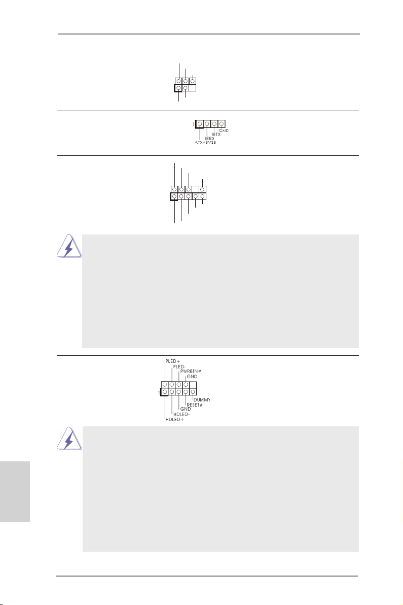
Infrared Module Header This header supports an
1
IRTX
+5VS B
DUMM Y
IRRX
GND
(5-pin IR1)
optional wireless transmitting
(see p.2 No. 20)
and receiving infrared module.
Consumer Infrared Module Header This header can be used to
(4-pin CIR1)
(see p.2 No. 22)
connect the remote
controller receiver.
1
GND
PRE SENC E#
MIC 2_R
MIC 2_L
MIC _RET
J_S ENSE
OUT 2_R
OUT _RET
OUT 2_L
Front Panel Audio Header This is an interface for the front
(9-pin HD_AUDIO1)
(see p.2 No. 25)
panel audio cable that allows
convenient connection and
control of audio devices.
1. High Denition Audio supports Jack Sensing, but the panel wire on
the chassis must support HDA to function correctly. Please follow the
instruction in our manual and chassis manual to install your system.
2. If you use AC’97 audio panel, please install it to the front panel audio
header as below:
A. Connect Mic_IN (MIC) to MIC2_L.
B. Connect Audio_R (RIN) to OUT2_R and Audio_L (LIN) to OUT2_L.
C. Connect Ground (GND) to Ground (GND).
D. MIC_RET and OUT_RET are for HD audio panel only. You don’t
need to connect them for AC’97 audio panel.
System Panel Header This header accommodates
(9-pin PANEL1)
(see p.2 No. 17)
several system front panel
functions.
Connect the power switch, reset switch and system status indicator
on the chassis to this header according to the pin assignments below.
Note the positive and negative pins before connecting the cables.
English
PWRBTN (Power Switch):
Connect to the power switch on the chassis front panel. You may congure the way to turn off your system using the power switch.
RESET (Reset Switch):
Connect to the reset switch on the chassis front panel. Press the reset
switch to restart the computer if the computer freezes and fails to perform a normal restart.
22
ASRock A75M-HVS Motherboard
PLED (System Power LED):
Connect to the power status indicator on the chassis front panel. The
LED is on when the system is operating. The LED keeps blinking
when the sys-tem is in S1 sleep state. The LED is off when the system
is in S3/S4 sleep state or powered off (S5).
HDLED (Hard Drive Activity LED):
Connect to the hard drive activity LED on the chassis front panel. The
LED is on when the hard drive is reading or writing data.
The front panel design may differ by chassis. A front panel module
mainly consists of power switch, reset switch, power LED, hard drive
activity LED, speaker and etc. When connecting your chassis front
panel module to this header, make sure the wire assignments and the
pin assign-ments are matched correctly.
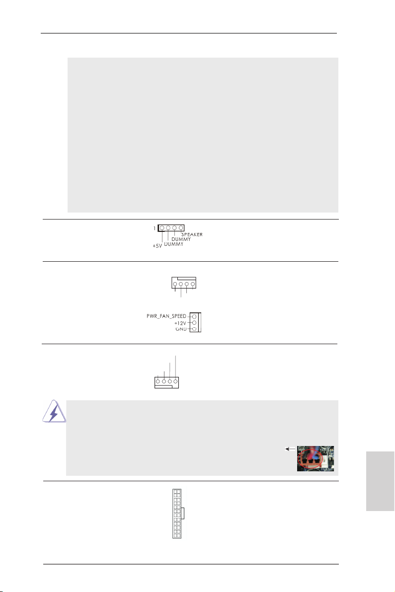
Chassis Speaker Header Please connect the chassis
(4-pin SPEAKER 1)
(see p.2 No. 13)
speaker to this header.
Chassis and Power Fan Connectors Please connect the fan cables
(4-pin CHA_FAN1)
(see p.2 No. 19)
ground pin.
(3-pin PWR_FAN1)
(see p.2 No. 30)
to the fan connectors and
match the black wire to the
FAN _SPE ED_C ONTR OL
CHA _FAN _SPE ED
+12 V
GND
CPU Fan Connectors Please connect the CPU fan
(4-pin CPU_FAN1)
(see p.2 No. 4)
cable to the connector and
match the black wire to the
ground pin.
FAN_ SPEE D_CO NTRO L
CPU _FAN_ SPEE D
+12 V
GND
1 2 3 4
Though this motherboard provides 4-Pin CPU fan (Quiet Fan) support, the 3-Pin
CPU fan still can work successfully even without the fan speed control function.
If you plan to connect the 3-Pin CPU fan to the CPU fan connector on this
motherboard, please connect it to Pin 1-3.
Pin 1-3 Connected
3-Pin Fan Installation
ATX Power Connector Please connect an ATX power
(24-pin ATXPWR1)
(see p.2 No. 6)
supply to this connector.
12 124
13
ASRock A75M-HVS Motherboard
English
23
Though this motherboard provides 24-pin ATX power connector,
it can still work if you adopt a traditional 20-pin ATX power supply.
To use the 20-pin ATX power supply, please plug your power
supply along with Pin 1 and Pin 13.
12
24
20-Pin ATX Power Supply Installation
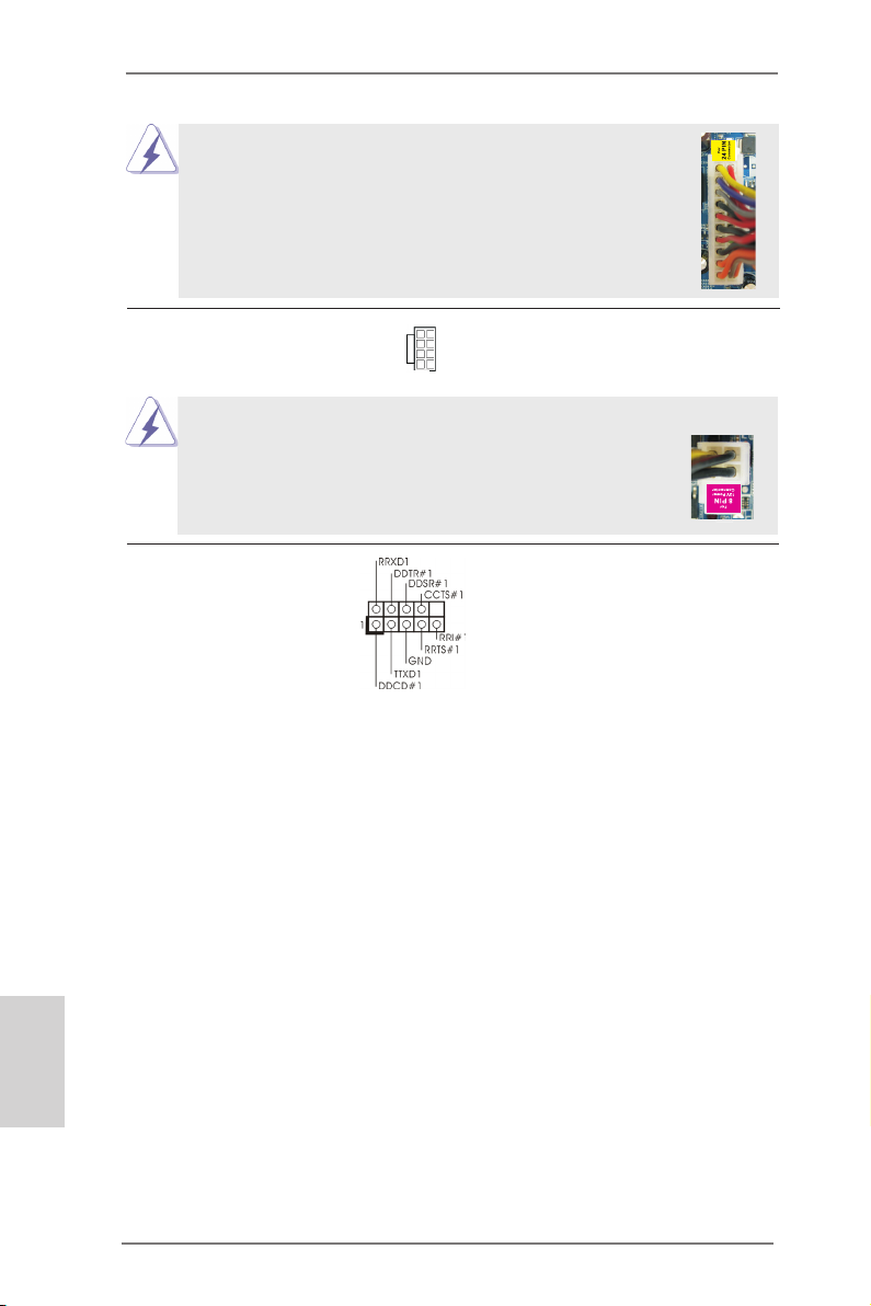
ATX 12V Power Connector Please connect an ATX 12V
(8-pin ATX12V1)
(see p.2 No. 1)
power supply to this connector.
5 1
8 4
1
Though this motherboard provides 8-pin ATX 12V power connector, it can still work
if you adopt a traditional 4-pin ATX 12V power supply. To use the
5 1
4-pin ATX power supply, please plug your power supply along with
Pin 1 and Pin 5.
4-Pin ATX 12V Power Supply Installation
8 4
Serial port Header This COM1 header supports a
(9-pin COM1)
(see p.2 No.16)
serial port module.
13
English
24
ASRock A75M-HVS Motherboard
2.10 Driver Installation Guide
To install the drivers to your system, please insert the support CD to your optical
drive rst. Then, the drivers compatible to your system can be auto-detected and
listed on the support CD driver page. Please follow the order from up to bottom side
to install those required drivers. Therefore, the drivers you install can work properly.
2.11 Installing Windows® 7 / 7 64-bit / VistaTM / VistaTM 64-bit / XP /
XP 64-bit With RAID Functions
If you want to install Windows® 7 / 7 64-bit / VistaTM / VistaTM 64-bit / XP / XP 64bit on your SATA3 HDDs with RAID functions, please refer to the document at the
following path in the Support CD for detailed procedures:
..\ RAID Installation Guide
2.12 Installing Windows® 7 / 7 64-bit / VistaTM / VistaTM 64-bit / XP /
XP 64-bit Without RAID Functions
If you want to install Windows® 7 / 7 64-bit / VistaTM / VistaTM 64-bit / XP / XP 64-bit
OS on your SATA3 HDDs without RAID functions, please follow below procedures
according to the OS you install.
2.12.1 Installing Windows® XP / XP 64-bit Without RAID Functions
If you want to install Windows® XP / XP 64-bit on your SATA3 HDDs without RAID
functions, please follow below steps.
Using SATA3 HDDs without NCQ and Hot Plug functions (IDE mode)
STEP 1: Set up UEFI.
A. Enter UEFI SETUP UTILITY Advanced screen Storage
Conguration.
B. Set the “SATA Mode” option to [IDE].
STEP 2: Install Windows® XP / XP 64-bit OS on your system.
ASRock A75M-HVS Motherboard
English
25
2.12.2 Installing Windows® 7 / 7 64-bit / VistaTM / VistaTM 64-bit
Without RAID Functions
If you want to install Windows® 7 / 7 64-bit / VistaTM / VistaTM 64-bit on your SATA3
HDDs without RAID functions, please follow below steps.
Using SATA3 HDDs without NCQ and Hot Plug functions (IDE mode)
STEP 1: Set up UEFI.
A. Enter UEFI SETUP UTILITY Advanced screen Storage
Conguration.
B. Set the “SATA Mode” option to [IDE].
STEP 2: Install Windows® 7 / 7 64-bit / VistaTM / VistaTM 64-bit OS on your
system.
Using SATA3 HDDs with NCQ and Hot Plug functions (AHCI mode)
STEP 1: Set up UEFI.
A. Enter UEFI SETUP UTILITY Advanced screen Storage
Conguration.
B. Set the “SATA Mode” option to [AHCI].
STEP 2: Install Windows® 7 / 7 64-bit / VistaTM / VistaTM 64-bit OS on your
system.
English
26
ASRock A75M-HVS Motherboard

3. BIOS Information
The Flash Memory on the motherboard stores BIOS Setup Utility. When you start up
the computer, please press <F2> or <Del> during the Power-On-Self-Test (POST)
to enter BIOS Setup utility; otherwise, POST continues with its test routines. If you
wish to enter BIOS Setup after POST, please restart the system by pressing <Ctl>
+ <Alt> + <Delete>, or pressing the reset button on the system chassis. The BIOS
Setup program is designed to be user-friendly. It is a menu-driven program, which
allows you to scroll through its various sub-menus and to select among the predetermined choices. For the detailed information about BIOS Setup, please refer to the
User Manual (PDF le) contained in the Support CD.
4. Software Support CD information
®
This motherboard supports various Microsoft
64-bit / VistaTM / Vista
the motherboard contains necessary drivers and useful utilities that will enhance
motherboard features. To begin using the Support CD, insert the CD into your CDROM drive. It will display the Main Menu automatically if “AUTORUN” is enabled in
your computer. If the Main Menu does not appear automatically, locate and doubleclick on the le “ASSETUP.EXE” from the BIN folder in the Support CD to display
the menus.
TM
64-bit / XP SP3 / XP 64-bit. The Support CD that came with
Windows® operating systems: 7 / 7
ASRock A75M-HVS Motherboard
English
27
1. Einführung
Wir danken Ihnen für den Kauf des ASRock A75M-HVS Motherboard, ein zuverlässiges Produkt, welches unter den ständigen, strengen Qualitätskontrollen von
ASRock gefertigt wurde. Es bietet Ihnen exzellente Leistung und robustes Design,
gemäß der Verpflichtung von ASRock zu Qualität und Halbarkeit. Diese Schnellinstallationsanleitung führt in das Motherboard und die schrittweise Installation
ein. Details über das Motherboard nden Sie in der Bedienungsanleitung auf der
Support-CD.
Da sich Motherboard-Spezikationen und BIOS-Software verändern
können, kann der Inhalt dieses Handbuches ebenfalls jederzeit geändert
werden. Für den Fall, dass sich Änderungen an diesem Handbuch
ergeben, wird eine neue Version auf der ASRock-Website, ohne weitere
Ankündigung, verfügbar sein. Die neuesten Grakkarten und unterstützten
CPUs sind auch auf der ASRock-Website aufgelistet.
ASRock-Website: http://www.asrock.com
Wenn Sie technische Unterstützung zu Ihrem Motherboard oder spezische
Informationen zu Ihrem Modell benötigen, besuchen Sie bitte unsere
Webseite:
www.asrock.com/support/index.asp
1.1 Kartoninhalt
ASRock A75M-HVS Motherboard
(Micro ATX-Formfaktor: 22.6 cm x 21.6 cm; 8.9 Zoll x 8.5 Zoll)
ASRock A75M-HVS Schnellinstallationsanleitung
ASRock A75M-HVS Support-CD
Zwei Serial ATA (SATA) -Datenkabel (optional)
Ein I/O Shield
Deutsch
28
ASRock erinnert…
Zur besseren Leistung unter Windows® 7 / 7, 64 Bit / Vista
64 Bit empfehlen wir, die Speicherkonguration im BIOS auf den AHCIModus einzustellen. Hinweise zu den BIOS-Einstellungen nden Sie in
der Bedienungsanleitung auf der mitgelieferten CD.
TM
/ VistaTM
ASRock A75M-HVS Motherboard
1.2 Spezifikationen
Plattform — Micro ATX-Formfaktor: 22.6 cm x 21.6 cm; 8.9 Zoll x 8.5 Zoll
— Festkondensator für CPU-Leistung
CPU — Unterstützt Sockel-FM1-100-W-Prozessoren
— Unterstützt Cool ‘n’ QuietTM-Technologie von AMD
— UMI-Link-GEN2
Chipsatz — AMD A75 FCH (Hudson-D3)
Speicher — Unterstützung von Dual-Kanal-Speichertechnologie
(siehe VORSICHT 1)
— 2 x Steckplätze für DDR3
— Unterstützt DDR3 2400+(OC)/1866/1600/1333/
1066/800 non-ECC, ungepufferter Speicher
(siehe VORSICHT 2)
— Max. Kapazität des Systemspeichers: 16GB
(siehe VORSICHT 3)
Erweiterungs- — 1 x PCI-Express-2.0-x16-Steckplätze
steckplätze — 1 x PCI Express 2.0 x1-Steckplätze
— 1 x PCI -Steckplätze
— Unterstützt AMD duale Grakkarten
Onboard-VGA — AMD Radeon HD 65XX/64XX-Grak
— DirectX 11, Pixel Shader 5.0
— Maximal gemeinsam genutzter Speicher 512MB
(siehe VORSICHT 4)
— Doppel-VGA Ausgabe: unterstützt HDMI und D-Sub Ports
durch unabhängige Bildschirmanzeige Kontrolleure
— Unterstützt HDMI 1.4a mit einer maximalen Auösung von
1920 x 1200 bei 60 Hz
— Unterstützt D-Sub mit einer maximalen Auösung von
1920 x 1600 bei 60 Hz
— Unterstützt Auto Lip Sync, Deep Color (12bpc), xvYCC und
HBR (High Bit Rate-Audio) mit HDMI (kompatibler HDMI-
Bildschirm erforderlich) (siehe VORSICHT 5)
— Unterstützt stereoskopisches 3D per Blu-ray mit HDMI 1.4a
— Unterstützt AMD Steady VideoTM: Neuartige Funktion der
Videonachbearbeitung für automatische Reduzierung von
Bildschwankungen bei Heim-/Online-Videos
— Unterstützt HDCP-Funktion mit HDMI-Port
— Unterstutzt 1080p Blu-ray (BD) / HD-DVD-Wiedergabe mit
HDMI-Port
Audio — 5.1 CH HD Audio (VIA® VT1705 Audio Codec)
Deutsch
ASRock A75M-HVS Motherboard
29
Deutsch
— Unterstützt THX TruStudio
TM
LAN — PCIE x1 Gigabit LAN 10/100/1000 Mb/s
— Realtek RTL8111E
— Unterstützt Wake-On-LAN
— Unterstützt LAN-Kabelerkennung
— Unterstützt energieefzientes Ethernet 802.3az
— Unterstützt PXE
E/A-Anschlüsse I/O Panel
an der — 1 x PS/2-Mausanschluss
Rückseite — 1 x PS/2-Tastaturanschluss
— 1 x D-Sub port
— 1 x HDMI port
— 2 x Standard-USB 2.0-Anschlüsse
— 4 x Standard-USB 3.0-Anschlüsse
— 1 x RJ-45 LAN Port mit LED (ACT/LINK LED und SPEED
LED)
— HD Audiobuchse: Audioeingang / Lautsprecher vorne /
Mikrofon
SATA3 — 6 x SATA 3-Anschluss mit 6,0 Gb/s, unterstützt RAID (RAID 0, RAID 1 und RAID 10), NCQ-, AHCI- und „Hot
Plugging“-Funktionen
USB3.0 — 4 x USB 3.0-Ports, unterstützt USB 1.0/2.0/3.0 mit bis zu
5 Gb/s
Anschlüsse — 6 x SATA3 6,0 GB/s-Anschlüsse
— 1 x Infrarot-Modul-Header
— 1 x Consumer Infrarot-Modul-Header
— 1 x Druckerport-Anschlussleiste
— 1 x COM-Anschluss-Header
— CPU/Gehäuse/Stromlüfter-Anschluss
— 24-pin ATX-Netz-Header
— 8-pin anschluss für 12V-ATX-Netzteil
— Anschluss für Audio auf der Gehäusevorderseite
— 3 x USB 2.0-Anschlüsse (Unterstützung 6 zusätzlicher
USB 2.0-Anschlüsse)
BIOS — 32Mb AMIs Legal BIOS UEFI mit GUI-Unterstützung
— Unterstützung für “Plug and Play”
— ACPI 1.1-Weckfunktionen
— JumperFree-Modus
— SMBIOS 2.3.1
— DRAM, VDDP, SB Stromspannung Multianpassung
30
ASRock A75M-HVS Motherboard
Loading…
Can You Chip In?
Dear Patron: Please don’t scroll past this. The Internet Archive is a nonprofit fighting for universal access to quality information. We build and maintain all our own systems, but we don’t charge for access, sell user information, or run ads. We’d be deeply grateful if you’d join the one in a thousand users that support us financially.
We understand that not everyone can donate right now, but if you can afford to contribute this Friday, we promise it will be put to good use. Our resources are crucial for knowledge lovers everywhere—so if you find all these bits and bytes useful, please pitch in.
Can You Chip In? Dear Patron: Please don’t scroll past this. The Internet Archive is working to keep the record straight by recording government websites, news publications, historical documents, and more. If you find our work useful, please pitch in.
Manual
View the manual for the Asrock A75M-HVS here, for free. This manual comes under the category motherboards and has been rated by 2 people with an average of a 8.
This manual is available in the following languages: English. Do you have a question about the Asrock A75M-HVS or do you need help?
Ask your question here
Asrock A75M-HVS specifications
Below you will find the product specifications and the manual specifications of the Asrock A75M-HVS.
Maximum internal memory
16 GB
Processor manufacturer
AMD
Motherboard form factor
micro ATX
Parallel processing technology support
Not supported
General
| Brand | Asrock |
| Model | A75M-HVS | A75M-HVS |
| Product | motherboard |
| EAN | 4711140877617, 5053086210509 |
| Language | English |
| Filetype | User manual (PDF) |
Memory
| Maximum internal memory | 16 GB |
| Number of memory slots | 2 |
| Supported memory clock speeds | 800,1066,1333,1600,1866,2400 MHz |
| Memory channels | Dual-channel |
Processor
| Processor manufacturer | AMD |
| Processor socket | Socket FM1 |
Internal I/O
| Power fan connector | Yes |
| USB 2.0 connectors | 3 |
| CPU fan connector | Yes |
| Number of COM connectors | 1 |
| ATX Power connector (24-pin) | Yes |
| Number of chassis fan connectors | 1 |
| Number of Parallel ATA connectors | 0 |
| Front panel audio connector | Yes |
| Number of SATA III connectors | 6 |
| EPS power connector (8-pin) | Yes |
Rear panel I/O ports
| PS/2 ports quantity | 2 |
| USB 2.0 ports quantity | 2 |
| Firewire (IEEE 1394) ports | 0 |
| Ethernet LAN (RJ-45) ports | 1 |
| Headphone outputs | 2 |
| Microphone in | Yes |
| VGA (D-Sub) ports quantity | 1 |
| eSATA ports quantity | 0 |
| DVI-D ports quantity | 0 |
| HDMI ports quantity | 1 |
| USB 3.2 Gen 1 (3.1 Gen 1) Type-A ports quantity | 4 |
Features
| Motherboard form factor | micro ATX |
| Motherboard chipset | AMD Hudson D3 |
| Compatible operating systems | Windows XP, Vista, 7 |
| Component for | PC |
| Audio output channels | 5.1 channels |
| Certification | FCC, CE, WHQL |
| Power source type | ATX |
Graphics
| Parallel processing technology support | Not supported |
| On-board graphics card | Yes |
| Graphics card family | AMD |
Expansion slots
| PCI Express x16 slots | 1 |
| PCI slots | 1 |
| PCI Express x1 slots | 1 |
Weight & dimensions
Other features
| Quick installation guide | Yes |
Packaging content
Network
| LAN controller | Realtek RTL8111E |
| Wake-on-LAN ready | Yes |
BIOS
| BIOS type | AMI |
| ACPI version | 1.1 |
show more
Frequently Asked Questions
Can’t find the answer to your question in the manual? You may find the answer to your question in the FAQs about the Asrock A75M-HVS below.
What is the width of the Asrock A75M-HVS?
The Asrock A75M-HVS has a width of 226 mm.
What is the depth of the Asrock A75M-HVS?
The Asrock A75M-HVS has a depth of 216 mm.
What certifications does the Asrock A75M-HVS have?
The Asrock A75M-HVS has the following certifications: FCC, CE, WHQL.
Is the manual of the Asrock A75M-HVS available in English?
Yes, the manual of the Asrock A75M-HVS is available in English .
Is your question not listed? Ask your question here
Manuals.eu
- Manuals.eu
- ASRock
- Computers & Peripherals
- Mainboards
- A75M-HVS
- User Manual
×
1
2
3
4
5
6
7
8
9
10
11
12
13
14
15
16
17
18
19
20
21
22
23
24
25
26
27
28
29
30
31
32
33
34
35
36
37
38
39
40
41
42
43
44
45
46
47
48
49
50
51
52
53
54
⟨
⟩
Copyright © Manuals.eu
Agreement
Privacy Policy
Contact us

1
ASRock A75M-HVS Motherboard
English
Copyright Notice:
No part of this installation guide may be reproduced, transcribed, transmitted, or trans-
lated in any language, in any form or by any means, except duplication of documentation
by the purchaser for backup purpose, without written consent of ASRock Inc.
Products and corporate names appearing in this guide may or may not be registered
trademarks or copyrights of their respective companies, and are used only for identifica-
tion or explanation and to the owners’ benefit, without intent to infringe.
Disclaimer:
Specifications and information contained in this guide are furnished for informational use
only and subject to change without notice, and should not be constructed as a commit-
ment by ASRock. ASRock assumes no responsibility for any errors or omissions that may
appear in this guide.
With respect to the contents of this guide, ASRock does not provide warranty of any kind,
either expressed or implied, including but not limited to the implied warranties or condi-
tions of merchantability or fitness for a particular purpose. In no event shall ASRock, its
directors, officers, employees, or agents be liable for any indirect, special, incidental, or
consequential damages (including damages for loss of profits, loss of business, loss of
data, interruption of business and the like), even if ASRock has been advised of the pos-
sibility of such damages arising from any defect or error in the guide or product.
This device complies with Part 15 of the FCC Rules. Operation is subject to the following
two conditions:
(1) this device may not cause harmful interference, and
(2) this device must accept any interference received, including interference that
may cause undesired operation.
CALIFORNIA, USA ONLY
The Lithium battery adopted on this motherboard contains Perchlorate, a toxic substance
controlled in Perchlorate Best Management Practices (BMP) regulations passed by the
California Legislature. When you discard the Lithium battery in California, USA, please
follow the related regulations in advance.
“Perchlorate Material-special handling may apply, see
www.dtsc.ca.gov/hazardouswaste/perchlorate”
ASRock Website: http://www.asrock.com
Published June 2011
Copyright©2011 ASRock INC. All rights reserved.