

960GM-GS3 FX /
960GM-S3 FX
User Manual
Version 1.0
Published September 2011
Copyright©2011 ASRock INC. All rights reserved.
11
1
11
Copyright Notice:Copyright Notice:
Copyright Notice:
Copyright Notice:Copyright Notice:
No part of this manual may be reproduced, transcribed, transmitted, or translated in
any language, in any form or by any means, except duplication of documentation by
the purchaser for backup purpose, without written consent of ASRock Inc.
Products and corporate names appearing in this manual may or may not be regis-
tered trademarks or copyrights of their respective companies, and are used only for
identification or explanation and to the owners’ benefit, without intent to infringe.
Disclaimer:Disclaimer:
Disclaimer:
Disclaimer:Disclaimer:
Specifications and information contained in this manual are furnished for informa-
tional use only and subject to change without notice, and should not be constructed
as a commitment by ASRock. ASRock assumes no responsibility for any errors or
omissions that may appear in this manual.
With respect to the contents of this manual, ASRock does not provide warranty of
any kind, either expressed or implied, including but not limited to the implied warran-
ties or conditions of merchantability or fitness for a particular purpose.
In no event shall ASRock, its directors, officers, employees, or agents be liable for
any indirect, special, incidental, or consequential damages (including damages for
loss of profits, loss of business, loss of data, interruption of business and the like),
even if ASRock has been advised of the possibility of such damages arising from any
defect or error in the manual or product.
This device complies with Part 15 of the FCC Rules. Operation is subject to the
following two conditions:
(1) this device may not cause harmful interference, and
(2) this device must accept any interference received, including interference that
may cause undesired operation.
CALIFORNIA, USA ONLY
The Lithium battery adopted on this motherboard contains Perchlorate, a toxic
substance controlled in Perchlorate Best Management Practices (BMP) regulations
passed by the California Legislature. When you discard the Lithium battery in
California, USA, please follow the related regulations in advance.
“Perchlorate Material-special handling may apply, see
www.dtsc.ca.gov/hazardouswaste/perchlorate”
ASRock Website: http://www.asrock.com
22
2
22

ContentsContents
Contents
ContentsContents
1.1.
IntroductionIntroduction
1.
Introduction
1.1.
IntroductionIntroduction
1.1 Package Contents …………………………………………………………… 5
1.2 Specifications ………………………………………………………………… 6
1.3 Motherboard Layout (960GM-GS3 FX / 960GM-S3 FX) …………. 11
1.4 I/O Panel (960GM-GS3 FX) ……………………………………………….. 12
1.5 I/O Panel (960GM-S3 FX) …………………………………………………. 13
2.2.
InstallationInstallation
2.
Installation
2.2.
InstallationInstallation
Pre-installation Precautions ……………………………………………………… 14
2.1 CPU Installation ………………………………………………………………. 15
2.2 Installation of CPU Fan and Heatsink ………………………………… 15
2.3 Installation of Memory Modules (DIMM) ……………………………… 16
2.4 Expansion Slots (PCI and PCI Express Slots) …………………….. 17
2.5 Multi Monitor Feature ………………………………………………………. 18
2.6 Jumpers Setup ……………………………………………………………….. 20
2.7 Onboard Headers and Connectors…………………………………… 21
2.8 SATAII Hard Disk Setup Guide ………………………………………….. 25
2.9 Serial ATA (SATA) / Serial ATAII (SATAII) Hard Disks
Installation ……………………………………………………………………… 26
2.10 Hot Plug and Hot Swap Functions for SATA / SATAII HDDs …. 26
2.11 SATA / SATAII HDD Hot Plug Feature and Operation Guide ….. 27
2.12 Driver Installation Guide …………………………………………………… 29
2.13 Installing Windows® XP / XP 64-bit / VistaTM / Vista
With RAID Functions ……………………………………………………….. 29
2.13.1 Installing Windows® XP / XP 64-bit With RAID
2.13.2 Installing Windows® VistaTM / Vista
2.14 Installing Windows® XP / XP 64-bit / VistaTM / Vista
Without RAID Functions …………………………………………………… 31
2.14.1 Installing Windows® XP / XP 64-bit Without RAID
2.14.2 Installing Windows® VistaTM / Vista
2.15 Untied Overclocking Technology ………………………………………. 33
…………………………………………………..…………………………………………………..
…………………………………………………..
…………………………………………………..…………………………………………………..
……………………………………………………..……………………………………………………..
……………………………………………………..
……………………………………………………..……………………………………………………..
TM
64-bit
Functions ………………………………………………………….. 29
Functions ……………………………………………………………. 30
Functions ……………………………………………………………. 31
Functions ……………………………………………………………. 32
TM
64-bit With RAID
TM
64-bit
TM
64-bit Without RAID
5 5
5
5 5
14 14
14
14 14
33
3
33

3.3.
BIOS SBIOS S
3.
BIOS S
3.3.
BIOS SBIOS S
3.1 Introduction ……………………………………………………………………. 34
3.2 Main Screen …………………………………………………………………… 35
3.3 OC Tweaker Screen …………………………………………………………. 36
3.4 Advanced Screen …………………………………………………………….. 41
3.5 Hardware Health Event Monitoring Screen …………………………… 51
3.6 Boot Screen …………………………………………………………………… 52
3.7 Security Screen ………………………………………………………………. 53
3.8 Exit Screen…………………………………………………………………….. 54
4.4.
Software SupportSoftware Support
4.
Software Support
4.4.
Software SupportSoftware Support
4.1 Install Operating System ………………………………………………….. 55
4.2 Support CD Information …………………………………………………….. 55
ETUP UTILITYETUP UTILITY
ETUP UTILITY
ETUP UTILITYETUP UTILITY
3.1.1 BIOS Menu Bar ……………………………………………………… 34
3.1.2 Navigation Keys ……………………………………………………. 35
3.4.1 CPU Configuration ………………………………………………….. 42
3.4.2 Chipset Configuration ……………………………………………… 43
3.4.3 ACPI Configuration …………………………………………………. 44
3.4.4 Storage Configuration ……………………………………………… 45
3.4.5 PCIPnP Configuration ……………………………………………… 47
3.4.6 Floppy Configuration ……………………………………………….. 48
3.4.7 Super IO Configuration ……………………………………………. 48
3.4.8 USB Configuration ………………………………………………….. 50
3.6.1 Boot Settings Configuration ……………………………………… 52
4.2.1 Running Support CD ……………………………………………….. 55
4.2.2 Drivers Menu …… ……… ……………… ……… ………. ……… …… 55
4.2.3 Utilities Menu ………………………………………………………… 55
4.2.4 Contact Information…………………………………………………. 55
…………………………………………………………………………………………
……………………………………………
…………………………………………………………………………………………
…………………………………………………………………………………………
……………………………………………
…………………………………………………………………………………………
34 34
34
34 34
55 55
55
55 55
44
4
44
1.1.
IntroductionIntroduction
1.
Introduction
1.1.
IntroductionIntroduction
Thank you for purchasing ASRock 960GM-GS3 FX / 960GM-S3 FX motherboard, a
reliable motherboard produced under ASRock’s consistently stringent quality control.
It delivers excellent performance with robust design conforming to ASRock’s com-
mitment to quality and endurance.
In this manual, chapter 1 and 2 contain introduction of the motherboard and step-by-
step guide to the hardware installation. Chapter 3 and 4 contain the configuration
guide to BIOS setup and information of the Support CD.
Because the motherboard specifications and the BIOS software might be
updated, the content of this manual will be subject to change without
notice. In case any modifications of this manual occur, the updated
version will be available on ASRock website without further notice. You
may find the latest VGA cards and CPU support lists on ASRock website
as well. ASRock website
If you require technical support related to this motherboard, please visit
our website for specific information about the model you are using.
www.asrock.com/support/index.asp
1.11.1
PP
ackack
1.1
1.11.1
ASRock 960GM-GS3 FX / 960GM-S3 FX Motherboard
(Micro ATX Form Factor: 9.6-in x 7.2-in, 24.4 cm x 18.3 cm)
ASRock 960GM-GS3 FX / 960GM-S3 FX Quick Installation Guide
ASRock 960GM-GS3 FX / 960GM-S3 FX Support CD
2 x Serial ATA (SATA) Data Cables (Optional)
1 x I/O Panel Shield
age Contentsage Contents
P
ack
age Contents
PP
ackack
age Contentsage Contents
http://www.asrock.com
55
5
55
1.21.2
SpecificationsSpecifications
1.2
Specifications
1.21.2
SpecificationsSpecifications
Platform — Micro ATX Form Factor: 9.6-in x 7.2-in, 24.4 cm x 18.3 cm
— Solid Capacitor for CPU power
CPU — Support for Socket AM3+ processors
— Support for Socket AM3 processors: AMD PhenomTM II X6 /
X4 / X3 / X2 (except 920 / 940) / Athlon II X4 / X3 / X2 /
Sempron processors
— Supports 8-Core CPU
— Supports AMD OverDriveTM with ACC feature (Advanced
Clock Calibration)
— AMD LIVE!TM Ready
— Supports AMD’s Cool ‘n’ QuietTM Technology
— FSB 2600 MHz (5.2 GT/s)
— Supports Untied Overclocking Technology (see CAUTION 1)
— Supports Hyper-Transport 3.0 (HT 3.0) Technology
Chipset — Northbridge: AMD 760G
— Southbridge: AMD SB710
Memory — Dual Channel DDR3 Memory Technology (see CAUTION 2)
— 2 x DDR3 DIMM slots
— Support DDR3 1800(OC)/1600(OC)/1333/1066/800 non-ECC,
un-buffered memory (see CAUTION 3)
— Max. capacity of system memory: 8GB (see CAUTION 4)
Expansion Slot — 1 x PCI Express 2.0 x16 slot (blue @ x16 mode)
— 1 x PCI Express 2.0 x1 slot
— 2 x PCI slots
Graphics — Integrated AMD Radeon HD 3000 graphics
— DX10 class iGPU, Pixel Shader 4.0
— Max. shared memory 512MB (see CAUTION 5)
— Supports D-Sub with max. resolution up to 2048×1536 @
60Hz
Audio — 5.1 CH HD Audio (Realtek ALC662 Audio Codec)
— Supports THX TruStudio
LAN — 960GM-GS3 FX
Realtek PCIE x1 Gigabit LAN RTL8111E,
speed 10/100/1000 Mb/s
— 960GM-S3 FX
Realtek PCIEx1 LAN 8105EL, speed 10/100 Mb/s
— Supports Wake-On-LAN
— Supports PXE
TM
66
6
66
Rear Panel I/O I/O Panel
— 1 x PS/2 Mouse Port
— 1 x PS/2 Keyboard Port
— 1 x Serial Port: COM1
— 1 x VGA Port
— 4 x Ready-to-Use USB 2.0 Ports
— 1 x RJ-45 LAN Port with LED (ACT/LINK LED and SPEED LED)
— HD Audio Jack: Line in / Front Speaker / Microphone
Connector — 4 x SATA2 3.0Gb/s connectors, support RAID (RAID 0, RAID 1,
RAID 10 and JBOD), NCQ, AHCI and “Hot Plug” functions
(see CAUTION 6)
— 1 x ATA133 IDE connector (supports 2 x IDE devices)
— 1 x Floppy connector
— 1 x Print port header
— CPU/Chassis/Power FAN connector
— 24 pin ATX power connector
— 4 pin 12V power connector
— Front panel audio connector
— 2 x USB 2.0 headers (support 4 USB 2.0 ports)
BIOS Feature — 8Mb AMI BIOS
— AMI Legal BIOS
— Supports “Plug and Play”
— ACPI 1.1 Compliance Wake Up Events
— Supports jumperfree
— SMBIOS 2.3.1 Support
— CPU, VCCM, NB Voltage Multi-adjustment
Support CD — Drivers, Utilities, AntiVirus Software (Trial Version),
AMD OverDriveTM Utility, CyberLink MediaEspresso 6.5 Trial,
ASRock Software Suite (CyberLink DVD Suite — OEM and Trial;
ASRock MAGIX Multimedia Suite — OEM)
Unique Feature — ASRock OC Tuner (see CAUTION 7)
— ASRock Intelligent Energy Saver (see CAUTION 8)
— ASRock Instant Boot
— ASRock Instant Flash (see CAUTION 9)
— ASRock OC DNA (see CAUTION 10)
— ASRock APP Charger (see CAUTION 11)
— ASRock SmartView (see CAUTION 12)
— ASRock XFast USB (see CAUTION 13)
— ASRock XFast LAN (see CAUTION 14)
— Hybrid Booster:
— CPU Frequency Stepless Control (see CAUTION 15)
— ASRock U-COP (see CAUTION 16)
77
7
77
— Boot Failure Guard (B.F.G.)
Hardware — CPU Temperature Sensing
Monitor — Chassis Temperature Sensing
— CPU/Chassis/Power Fan Tachometer
— CPU Quiet Fan
— Voltage Monitoring: +12V, +5V, +3.3V, Vcore
OS — Microsoft
®
Windows® 7 / 7 64-bit / Vista
TM
/ VistaTM 64-bit
/ XP / XP Media Center / XP 64-bit compliant
Certifications — FCC, CE, WHQL
— ErP/EuP Ready (ErP/EuP ready power supply is required)
(see CAUTION 17)
* For detailed product information, please visit our website: http://www.asrock.com
WARNING
Please realize that there is a certain risk involved with overclocking, including adjusting
the setting in the BIOS, applying Untied Overclocking Technology, or using the third-
party overclocking tools. Overclocking may affect your system stability, or even
cause damage to the components and devices of your system. It should be done at
your own risk and expense. We are not responsible for possible damage caused by
overclocking.
CAUTION!
1. This motherboard supports Untied Overclocking Technology. Please read
“Untied Overclocking Technology” on page 33 for details.
2. This motherboard supports Dual Channel Memory Technology. Before you
implement Dual Channel Memory Technology, make sure to read the
installation guide of memory modules on page 16 for proper installation.
3. Whether 1800/1600MHz memory speed is supported depends on the
AM3/AM3+ CPU you adopt. If you want to adopt DDR3 1800/1600 memory
module on this motherboard, please refer to the memory support list on
our website for the compatible memory modules.
ASRock website
4. Due to the operating system limitation, the actual memory size may be
less than 4GB for the reservation for system usage under Windows® 7 /
TM
Vista
/ XP. For Windows® OS with 64-bit CPU, there is no such limitation.
5. The maximum shared memory size is defined by the chipset vendor and
is subject to change. Please check AMD website for the latest information.
6. Before installing SATAII hard disk to SATAII connector, please read the “SATAII
Hard Disk Setup Guide” on page 25 to adjust your SATAII hard disk drive to
SATAII mode. You can also connect SATA hard disk to SATAII connector
directly.
http://www.asrock.com
88
8
88
7. It is a user-friendly ASRock overclocking tool which allows you to surveil
your system by hardware monitor function and overclock your hardware
devices to get the best system performance under Windows
environment. Please visit our website for the operation procedures of
ASRock OC Tuner. ASRock website:
8. Featuring an advanced proprietary hardware and software design,
Intelligent Energy Saver is a revolutionary technology that delivers
unparalleled power savings. The voltage regulator can reduce the number
of output phases to improve efficiency when the CPU cores are idle. In
other words, it is able to provide exceptional power saving and improve
power efficiency without sacrificing computing performance. To use Intel-
ligent Energy Saver function, please enable Cool ‘n’ Quiet option in the
BIOS setup in advance. Please visit our website for the operation proce-
dures of Intelligent Energy Saver.
ASRock website: http://www.asrock.com
9. ASRock Instant Flash is a BIOS flash utility embedded in Flash ROM.
This convenient BIOS update tool allows you to update system BIOS
without entering operating systems first like MS-DOS or Windows
this utility, you can press <F6> key during the POST or press <F2> key to
BIOS setup menu to access ASRock Instant Flash. Just launch this tool
and save the new BIOS file to your USB flash drive, floppy disk or hard
drive, then you can update your BIOS only in a few clicks without prepar-
ing an additional floppy diskette or other complicated flash utility. Please
be noted that the USB flash drive or hard drive must use FAT32/16/12 file
system.
10. The software name itself – OC DNA literally tells you what it is capable of.
OC DNA, an exclusive utility developed by ASRock, provides a conve-
nient way for the user to record the OC settings and share with others. It
helps you to save your overclocking record under the operating system
and simplifies the complicated recording process of overclocking settings.
With OC DNA, you can save your OC settings as a profile and share with
your friends! Your friends then can load the OC profile to their own system
to get the same OC settings as yours! Please be noticed that the OC
profile can only be shared and worked on the same motherboard.
11. If you desire a faster, less restricted way of charging your Apple devices,
such as iPhone/iPod/iPad Touch, ASRock has prepared a wonderful
solution for you — ASRock APP Charger. Simply installing the APP Charger
driver, it makes your iPhone charged much quickly from your computer
and up to 40% faster than before. ASRock APP Charger allows you to
quickly charge many Apple devices simultaneously and even supports
continuous charging when your PC enters into Standby mode (S1),
Suspend to RAM (S3), hibernation mode (S4) or power off (S5). With
APP Charger driver installed, you can easily enjoy the marvelous charg-
ing experience than ever.
ASRock website:
http://www.asrock.com/Feature/AppCharger/index.asp
http://www.asrock.com
®
. With
®
99
9
99
12. SmartView, a new function of internet browser, is the smart start page
for IE that combines your most visited web sites, your history, your
Facebook friends and your real-time newsfeed into an enhanced view
for a more personal Internet experience. ASRock motherboards are
exclusively equipped with the SmartView utility that helps you keep in
touch with friends on-the-go. To use SmartView feature, please make
sure your OS version is Windows® 7 / 7 64 bit / VistaTM / VistaTM 64 bit,
and your browser version is IE8.
ASRock website: http://www.asrock.com/Feature/SmartView/index.asp
13. ASRock XFast USB can boost USB storage device performance. The
performance may depend on the property of the device.
14. ASRock XFast LAN provides a faster internet access, which includes
below benefits. LAN Application Prioritization: You can configure your
application priority ideally and/or add new programs. Lower Latency in
Game: After setting online game priority higher, it can lower the latency
in game. Traffic Shaping: You can watch Youtube HD video and down-
load files simultaneously. Real-Time Analysis of Your Data: With the
status window, you can easily recognize which data streams you are
currently transferring.
15. Although this motherboard offers stepless control, it is not recom-
mended to perform over-clocking. Frequencies other than the recom-
mended CPU bus frequencies may cause the instability of the system
or damage the CPU.
16. While CPU overheat is detected, the system will automatically shutdown.
Before you resume the system, please check if the CPU fan on the
motherboard functions properly and unplug the power cord, then plug it
back again. To improve heat dissipation, remember to spray thermal
grease between the CPU and the heatsink when you install the PC
system.
17. EuP, stands for Energy Using Product, was a provision regulated by Euro-
pean Union to define the power consumption for the completed system.
According to EuP, the total AC power of the completed system shall be
under 1.00W in off mode condition. To meet EuP standard, an EuP ready
motherboard and an EuP ready power supply are required. According to
Intel’s suggestion, the EuP ready power supply must meet the standard of
5v standby power efficiency is higher than 50% under 100 mA current
consumption. For EuP ready power supply selection, we recommend you
checking with the power supply manufacturer for more details.
1010
10
1010
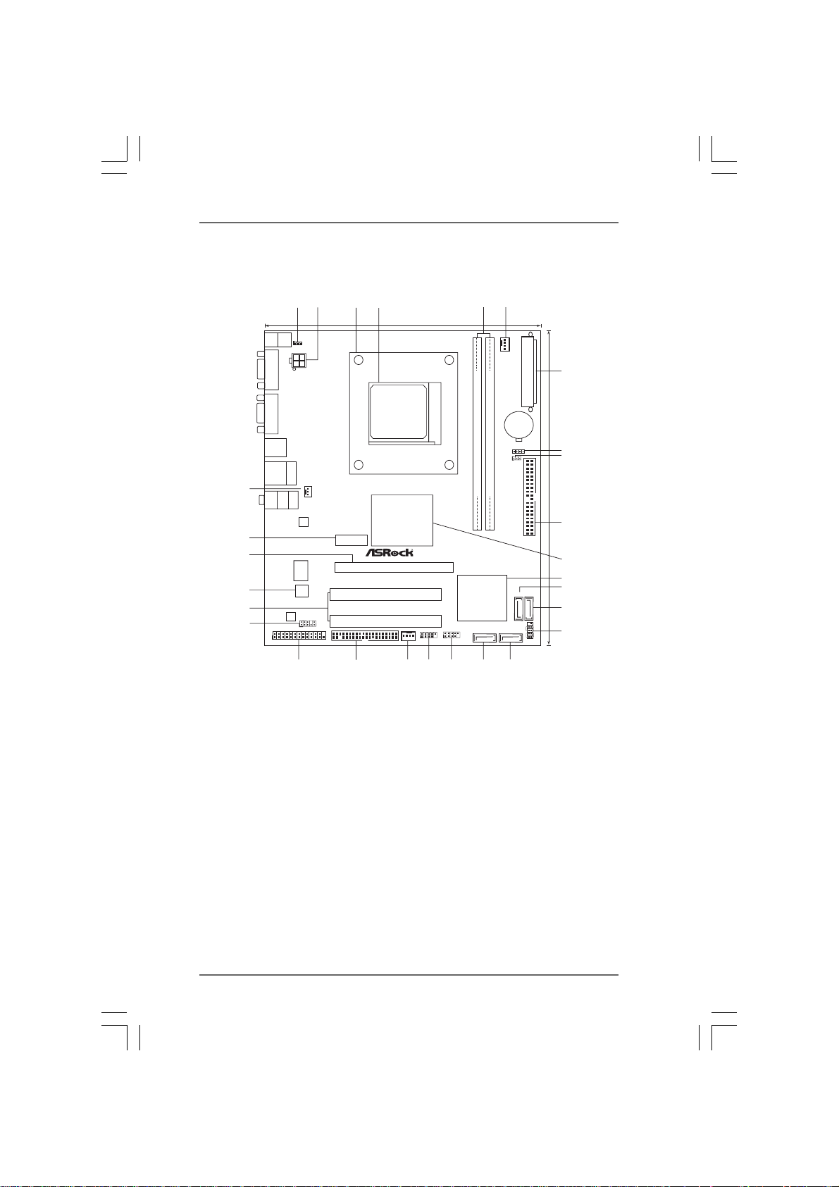
1.3 Motherboard L1.3 Motherboard L
1.3 Motherboard L
1.3 Motherboard L1.3 Motherboard L
ayout (960GM-ayout (960GM-
ayout (960GM-
ayout (960GM-ayout (960GM-
GS3 FX / 960GM-S3 FX)GS3 FX / 960GM-S3 FX)
GS3 FX / 960GM-S3 FX)
GS3 FX / 960GM-S3 FX)GS3 FX / 960GM-S3 FX)
1
Keyboard
Mouse
PS2
PS2
1
PS2_USB_PW1
COM1
ATX12V1
VGA1
USB2.0
T: US B2
B:USB3
USB2.0
Top:
T: US B0
RJ-45
B:USB1
28
Bottom:
MIC IN
Top:
LINE IN
Center:
FRONT
PWR_FAN1
LAN
27
26
Super
I/O
ErP/EuP Ready
25
24
23
8Mb
BIOS
AUDIO
CODEC
HD_AUDIO1
1
1
LPT1
2
HT3.0
Phenom II
Support 8-CoreCPU
Design inTaipei
FLOPPY1
DX10
PCIE1
3
2122
4
18.3cm (7.2-in)
Dual Channel
AMD
760G
Chipset
PCIE2
PCI1
PCI2
CHA_FAN1
USB6_7
1
SOCKET AM3
RoHS
USB4_5
1
181920
5 6
AM3+
FSB2.6GHz
FSB800
DDR3_B1 (64bit, 240-pin module)
DDR3_A1 (64bit, 240-pin module)
DDR3 1800
AMD
SB710
Chipset
SATAII_1(PORT0) SATAII_2(PORT1)
17
CPU_FAN1
BATTERY
16
CMOS
SPEAKER1
1
1
CLRCMOS1
SATAII_3(SATAII_4
PORT2) (PORT3)
PANEL1
ATXPWR1
IDE1
PLEDPWRBTN
1
7
8
9
24.4cm (9.6-in)
10
11
12
13
14
15
HDLED RESET
1 PS2_USB_PW1 Jumper 15 System Panel Header (PANEL1, White)
2 ATX 12V Power Connector (ATX12V1) 16 Secondary SAT AII Connector
3 CPU Heatsink Retention Module (SATAII_2 (PORT 1))
4 AM3 CPU Socket 17 Primary SAT AII Connector
5 2 x 240-pin DDR3 DIMM Slots (SA TAII_1 (PORT 0))
(Dual Channel: DDR3_A1, DDR3_B1; Blue) 18 USB 2.0 Header (USB4_5, Blue)
6 CPU Fan Connector (CPU_FAN1) 19 USB 2.0 Header (USB6_7, Blue)
7 A TX Power Conne ctor (ATXPWR1) 20 Chassis Fan Connector (CHA_FAN1)
8 Chassis Speaker Header 21 Floppy Connector (FLOPPY1)
(SPEAKER 1, White) 22 Print Port Header (LPT1, White)
9 Clear CMOS Jumper (CLRCMOS1) 23 Front Panel Audio Header
10 Primary IDE Connector (IDE1, Blue) (HD_AUDIO1, White)
11 Northbridge Controller 24 PCI Slots (PCI1- 2)
12 Southbridge Controller 25 SPI Flash Memory (8Mb)
13 Third SAT AII Connector (SATAII_3 (PORT 2)) 26 PCI Express 2.0 x16 Slot (PCIE2; Blue)
14 Fourth SAT AII Connector (SATAII_4 (PORT 3)) 27 PCI Express 2.0 x1 Slot (PCIE1; Blue)
28 Power Fan Connector (PWR_FAN1)
1111
11
1111
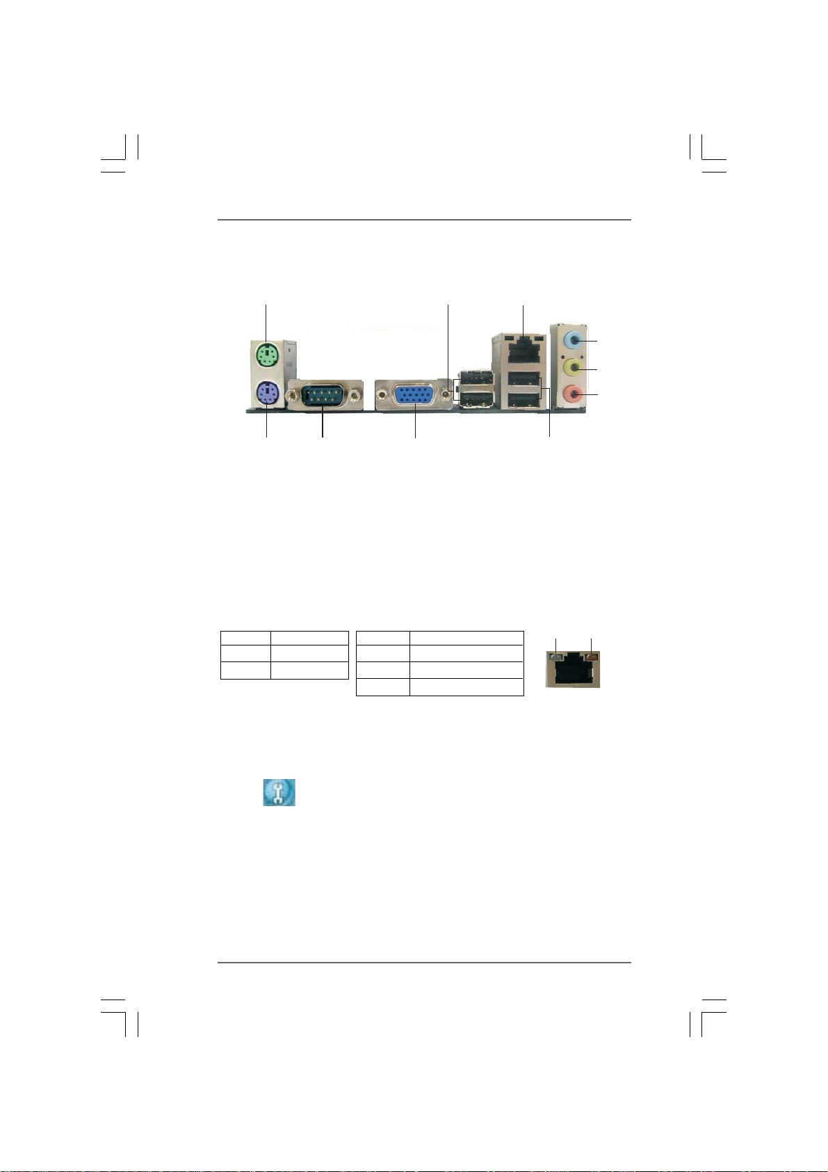
1.4 I/O P1.4 I/O P
1.4 I/O P
1.4 I/O P1.4 I/O P
anel (960GM-anel (960GM-
anel (960GM-
anel (960GM-anel (960GM-
GS3 FX)GS3 FX)
GS3 FX)
GS3 FX)GS3 FX)
1
2
3
4
5
6
10
1 PS/2 Mouse Port (Green) 6 Microphone (Pink)
2 USB 2.0 Ports (USB23) 7 USB 2.0 Ports (USB01)
* 3 RJ-45 Port 8 VGA Port
4 Line In (Light Blue) 9 COM Port
5 Line Out (Lime) 10 PS/2 Keyboard Port (Purple)
* There are two LED next to the LAN port. Please refer to the table below for the LAN port LED
indications.
Activity/Link LED SPEED LED
Status Description Status Description
9
8
LAN Port LED Indications
Off No Activity Off 10Mbps connection
Blinking Data Activity Orange 100Mbps connection
Green 1Gbps connection
7
ACT/LINK
LED
LAN Port
SPEED
LED
* To enable Multi-Streaming function, you need to connect a front panel audio cable to the front
panel audio header. Please refer to below steps for the software setting of Multi-Streaming.
For Windows® XP:
After restarting your computer, you will find “Mixer” tool on your system. Please select “Mixer
ToolBox” , click “Enable playback multi-streaming”, and click “ok”. Choose “2CH” or
“4CH” and then you are allowed to select “Realtek HDA Primary output” to use Rear Speaker
and Front Speaker, or select “Realtek HDA Audio 2nd output” to use front panel audio. Then
reboot your system.
For Windows
After restarting your computer, please double-click “Realtek HD Audio Manager” on the
system tray. Set “Speaker Configuration” to “Quadraphonic” or “Stereo”. Click “Device
advanced settings”, choose “Make front and rear output devices playbacks two different audio
streams simultaneously”, and click “ok”. Then reboot your system.
®
7 / VistaTM:
1212
12
1212
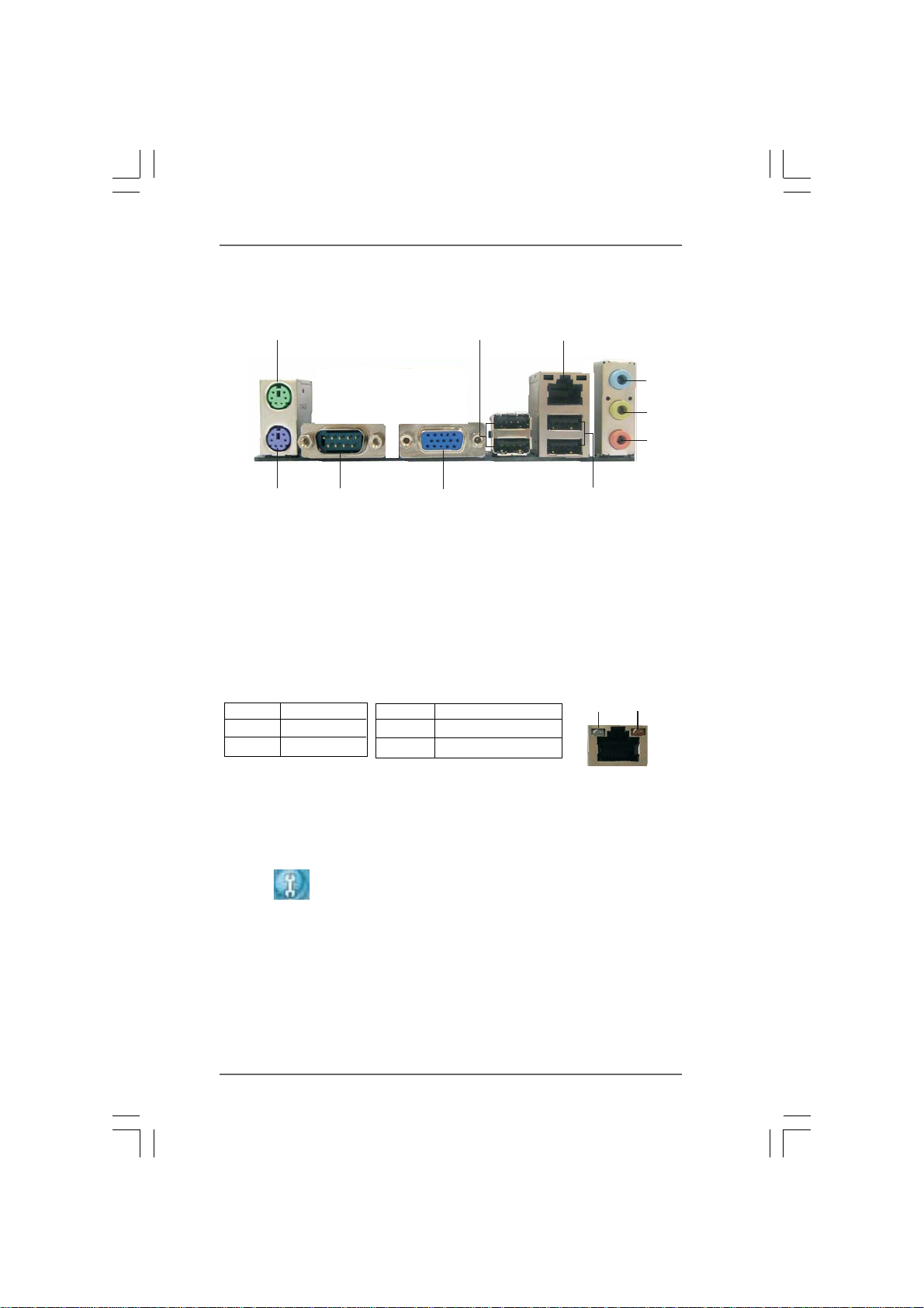
1.5 I/O P1.5 I/O P
1.5 I/O P
1.5 I/O P1.5 I/O P
anel (960GM-S3 FX)anel (960GM-S3 FX)
anel (960GM-S3 FX)
anel (960GM-S3 FX)anel (960GM-S3 FX)
1
2
3
4
5
6
10
1 PS/2 Mouse Port (Green) 6 Microphone (Pink)
2 USB 2.0 Ports (USB23) 7 USB 2.0 Ports (USB01)
* 3 RJ-45 Port 8 VGA Port
4 Line In (Light Blue) 9 COM Port
5 Line Out (Lime) 10 PS/2 Keyboard Port (Purple)
* There are two LED next to the LAN port. Please refer to the table below for the LAN port LED
indications.
Activity/Link LED SPEED LED
Status Description Status Description
9
8
LAN Port LED Indications
Off No Activity Off 10Mbps connection
Blinking Data Activity Orange 100Mbps connection
7
ACT/LINK
LED
LAN Port
SPEED
LED
* To enable Multi-Streaming function, you need to connect a front panel audio cable to the front
panel audio header. Please refer to below steps for the software setting of Multi-Streaming.
For Windows® XP:
After restarting your computer, you will find “Mixer” tool on your system. Please select “Mixer
ToolBox” , click “Enable playback multi-streaming”, and click “ok”. Choose “2CH” or
“4CH” and then you are allowed to select “Realtek HDA Primary output” to use Rear Speaker
and Front Speaker, or select “Realtek HDA Audio 2nd output” to use front panel audio. Then
reboot your system.
For Windows
After restarting your computer, please double-click “Realtek HD Audio Manager” on the
system tray. Set “Speaker Configuration” to “Quadraphonic” or “Stereo”. Click “Device
advanced settings”, choose “Make front and rear output devices playbacks two different audio
streams simultaneously”, and click “ok”. Then reboot your system.
®
7 / VistaTM:
1313
13
1313
2.2.
InstallationInstallation
2.
Installation
2.2.
InstallationInstallation
This is a Micro ATX form factor (9.6-in x 7.2-in, 24.4 cm x 18.3 cm) motherboard.
Before you install the motherboard, study the configuration of your chassis to en-
sure that the motherboard fits into it.
Pre-installation PrecautionsPre-installation Precautions
Pre-installation Precautions
Pre-installation PrecautionsPre-installation Precautions
Take note of the following precautions before you install motherboard
components or change any motherboard settings.
Before you install or remove any component, ensure that the
power is switched off or the power cord is detached from the
power supply. Failure to do so may cause severe damage to the
motherboard, peripherals, and/or components.
1. Unplug the power cord from the wall socket before touching any
component.
2. To avoid damaging the motherboard components due to static
electricity, NEVER place your motherboard directly on the carpet or
the like. Also remember to use a grounded wrist strap or touch a
safety grounded object before you handle components.
3. Hold components by the edges and do not touch the ICs.
4. Whenever you uninstall any component, place it on a grounded anti-
static pad or in the bag that comes with the component.
5. When placing screws into the screw holes to secure the motherboard
to the chassis, please do not over-tighten the screws! Doing so may
damage the motherboard.
1414
14
1414
2.12.1
CPU InstallationCPU Installation
2.1
CPU Installation
2.12.1
CPU InstallationCPU Installation
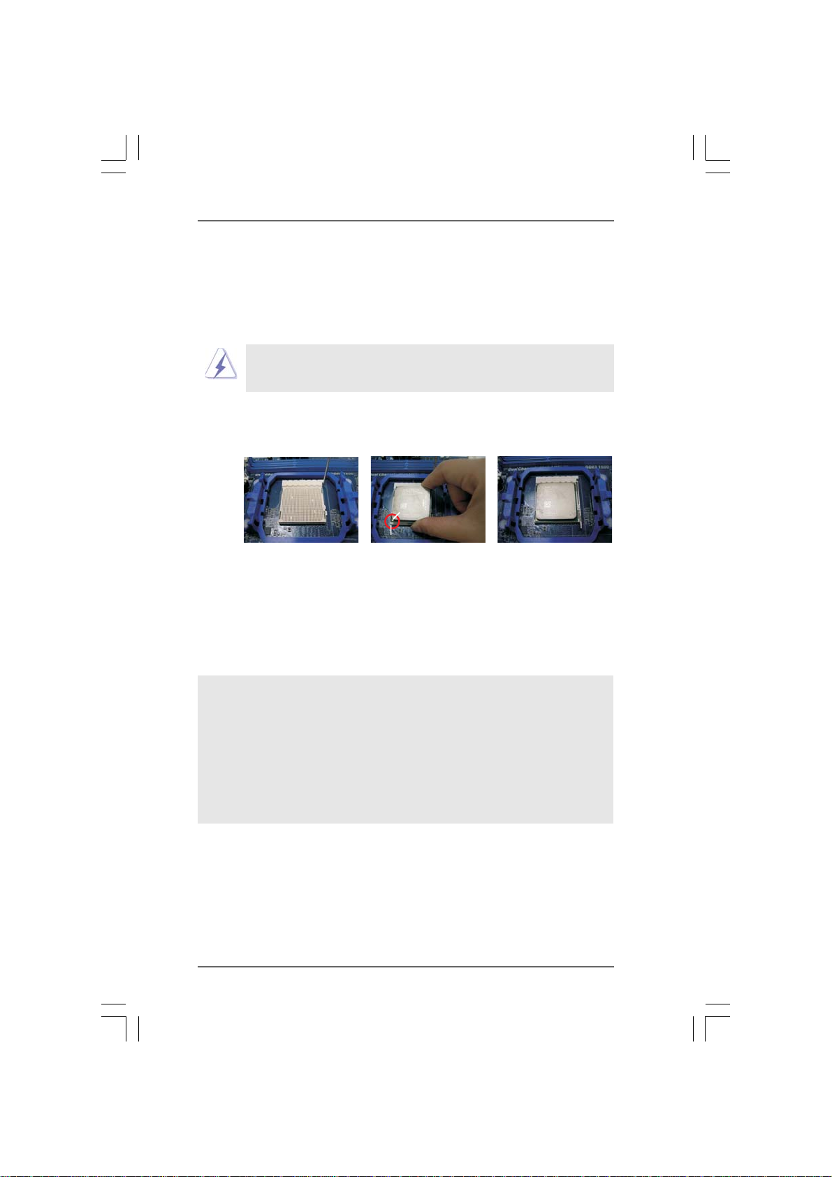
Step 1. Unlock the socket by lifting the lever up to a 90
o
angle.
Step 2. Position the CPU directly above the socket such that the CPU corner with
the golden triangle matches the socket corner with a small triangle.
Step 3. Carefully insert the CPU into the socket until it fits in place.
The CPU fits only in one correct orientation. DO NOT force the CPU
into the socket to avoid bending of the pins.
Step 4. When the CPU is in place, press it firmly on the socket while you push
down the socket lever to secure the CPU. The lever clicks on the side tab
to indicate that it is locked.
Lever 90° Up
CPU Golden Triangle
Socker Corner Small Triangle
STEP 1:
Lift Up The Socket Lever
2.22.2
Installation of CPU Fan and HeatsinkInstallation of CPU Fan and Heatsink
2.2
Installation of CPU Fan and Heatsink
2.22.2
Installation of CPU Fan and HeatsinkInstallation of CPU Fan and Heatsink
STEP 2 / STEP 3:
Match The CPU Golden Triangle
To The Socket Corner Small
Triangle
STEP 4:
Push Down And Lock
The Socket Lever
After you install the CPU into this motherboard, it is necessary to install a
larger heatsink and cooling fan to dissipate heat. You also need to spray
thermal grease between the CPU and the heatsink to improve heat
dissipation. Make sure that the CPU and the heatsink are securely fas-
tened and in good contact with each other. Then connect the CPU fan to
the CPU FAN connector (CPU_FAN1, see Page 11, No. 6). For proper
installation, please kindly refer to the instruction manuals of the CPU fan
and the heatsink.
1515
15
1515
2.3 Installation of Memor2.3 Installation of Memor
2.3 Installation of Memor
2.3 Installation of Memor2.3 Installation of Memor
960GM-GS3 FX / 960GM-S3 FX motherboard provides two 240-pin DDR3 (Double Data
Rate 3) DIMM slots, and supports Dual Channel Memory Technology. For dual channel
configuration, you always need to install two identical (the same brand, speed,
size and chip-type) memory modules in the DDR3 DIMM slots to activate Dual Channel
Memory Technology. Otherwise, it will operate at single channel mode.
1. It is not allowed to install a DDR or DDR2 memory module into
DDR3 slot;otherwise, this motherboard and DIMM may be damaged.
2. If you install only one memory module or two non-identical memory
modules, it is unable to activate the Dual Channel Memory Technology.
Installing a DIMMInstalling a DIMM
Installing a DIMM
Installing a DIMMInstalling a DIMM
Please make sure to disconnect power supply before adding or
removing DIMMs or the system components.
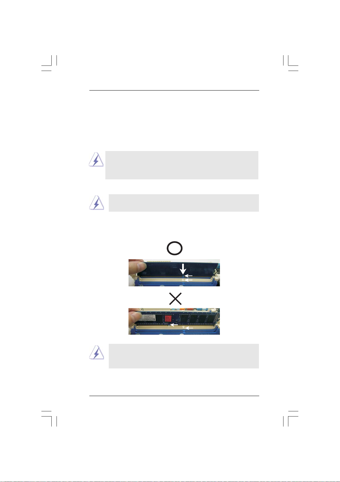
Step 1. Unlock a DIMM slot by pressing the retaining clips outward.
Step 2. Align a DIMM on the slot such that the notch on the DIMM matches the break
on the slot.
y Modules (DIMM)y Modules (DIMM)
y Modules (DIMM)
y Modules (DIMM)y Modules (DIMM)
notch
break
notch
break
The DIMM only fits in one correct orientation. It will cause permanent
damage to the motherboard and the DIMM if you force the DIMM into the
slot at incorrect orientation.
Step 3. Firmly insert the DIMM into the slot until the retaining clips at both ends fully
snap back in place and the DIMM is properly seated.
1616
16
1616

2.4 Expansion Slots (PCI and PCI Express Slots)2.4 Expansion Slots (PCI and PCI Express Slots)
2.4 Expansion Slots (PCI and PCI Express Slots)
2.4 Expansion Slots (PCI and PCI Express Slots)2.4 Expansion Slots (PCI and PCI Express Slots)
There are 2 PCI slots and 2 PCI Express slots on this motherboard.
PCI slots: PCI slots are used to install expansion cards that have the 32-bit PCI
interface.
PCIE slots:
PCIE1 (PCIE x1 slot; Blue) is used for PCI Express cards with x1 lane
width cards, such as Gigabit LAN card, SATA2 card, etc.
PCIE2 (PCIE x16 slot; Blue) is used for PCI Express cards with x16
lane width graphics cards.
Installing an expansion cardInstalling an expansion card
Installing an expansion card
Installing an expansion cardInstalling an expansion card
Step 1. Before installing the expansion card, please make sure that the power
supply is switched off or the power cord is unplugged. Please read the
documentation of the expansion card and make necessary hardware
settings for the card before you start the installation.
Step 2. Remove the bracket facing the slot that you intend to use. Keep the screws
for later use.
Step 3. Align the card connector with the slot and press firmly until the card is
completely seated on the slot.
Step 4. Fasten the card to the chassis with screws.
1717
17
1717
Loading…
11
11
1
ASRock 960GM-GS3 FX / 960GM-S3 FX Motherboard
EnglishEnglish
EnglishEnglish
English
Copyright Notice:Copyright Notice:
Copyright Notice:Copyright Notice:
Copyright Notice:
No part of this installation guide may be reproduced, transcribed, transmitted, or trans-
lated in any language, in any form or by any means, except duplication of documen-
tation by the purchaser for backup purpose, without written consent of ASRock Inc.
Products and corporate names appearing in this guide may or may not be registered
trademarks or copyrights of their respective companies, and are used only for identifica-
tion or explanation and to the owners’ benefit, without intent to infringe.
Disclaimer:Disclaimer:
Disclaimer:Disclaimer:
Disclaimer:
Specifications and information contained in this guide are furnished for informational
use only and subject to change without notice, and should not be constructed as a
commitment by ASRock. ASRock assumes no responsibility for any errors or omissions
that may appear in this guide.
With respect to the contents of this guide, ASRock does not provide warranty of any kind,
either expressed or implied, including but not limited to the implied warranties or
conditions of merchantability or fitness for a particular purpose. In no event shall
ASRock, its directors, officers, employees, or agents be liable for any indirect, special,
incidental, or consequential damages (including damages for loss of profits, loss of
business, loss of data, interruption of business and the like), even if ASRock has been
advised of the possibility of such damages arising from any defect or error in the guide
or product.
This device complies with Part 15 of the FCC Rules. Operation is subject to the
following two conditions:
(1) this device may not cause harmful interference, and
(2) this device must accept any interference received, including interference that
may cause undesired operation.
Published September 2011
Copyright©2011 ASRock INC. All rights reserved.
CALIFORNIA, USA ONLY
The Lithium battery adopted on this motherboard contains Perchlorate, a toxic
substance controlled in Perchlorate Best Management Practices (BMP) regulations
passed by the California Legislature. When you discard the Lithium battery in
California, USA, please follow the related regulations in advance.
“Perchlorate Material-special handling may apply, see
www.dtsc.ca.gov/hazardouswaste/perchlorate”
ASRock Website: http://www.asrock.com
Can You Chip In?
Dear Patron: Please don’t scroll past this. The Internet Archive is a nonprofit fighting for universal access to quality information. We build and maintain all our own systems, but we don’t charge for access, sell user information, or run ads. We’d be deeply grateful if you’d join the one in a thousand users that support us financially.
We understand that not everyone can donate right now, but if you can afford to contribute this Thursday, we promise it will be put to good use. Our resources are crucial for knowledge lovers everywhere—so if you find all these bits and bytes useful, please pitch in.
Can You Chip In? Dear Patron: Please don’t scroll past this. The Internet Archive is working to keep the record straight by recording government websites, news publications, historical documents, and more. If you find our work useful, please pitch in.
Manuals.eu
- Manuals.eu
- ASRock
- Computers & Peripherals
- Mainboards
- 960GM-GS3 FX
- User Manual
×
1
2
3
4
5
6
7
8
9
10
11
12
13
14
15
16
17
18
19
20
21
22
23
24
25
26
27
28
29
30
31
32
33
34
35
36
37
38
39
40
41
42
43
44
45
46
47
48
49
50
51
52
53
54
55
⟨
⟩
Copyright © Manuals.eu
Agreement
Privacy Policy
Contact us
- Инструкции и руководства
- Бренды
- Asrock
- 960GM-GS3 FX
Модели
90-MXGKF0-A0UAYZПоказать ещё
, 960GM-GS3 FX
Скрыть
Справочник Пользователя (English, Deutsch, Français, …)
Справочник Пользователя
Содержание
-
English
1
-
German
24
-
French
37
-
Italian
50
-
Spanish
62
-
Russian
75
-
Portuguese
87
-
Turkish
99
-
Korean
111
-
Japanese
123
-
Simplified Chinese
135
-
Traditional Chinese
146
-
Indonesian
156
-
- Размер:
- 7,1 МБ
-
- Страницы:
- 159
-
- Языки:
- English, Deutsch, Français, Italiano, Español, Português
Просмотреть