
Руководство по установке и использованию
Back-UPS® BR900G-RS
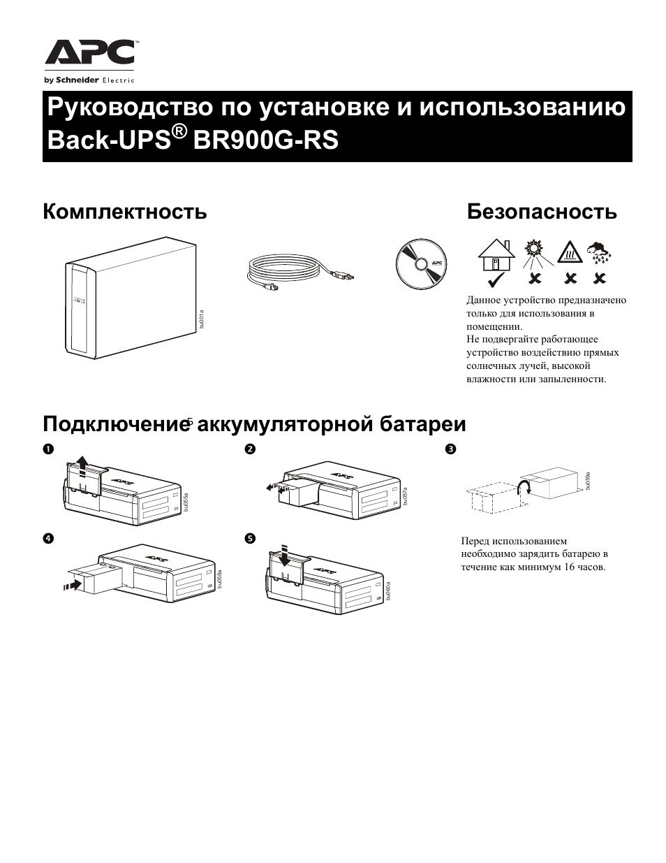
Комплектность Безопасность
Данное устройство предназначено
только для использования в
помещении.
Не подвергайте работающее
устройство воздействию прямых
солнечных лучей, высокой
влажности или запыленности.
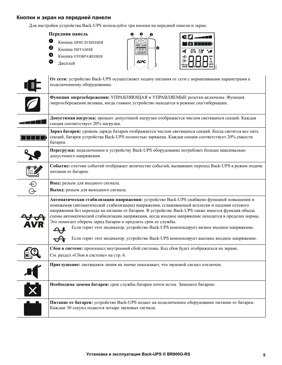
Подключение аккумуляторной батареи
Б
123
bu059a
bu055a
45
bu058a
bu057a
Перед использованием
необходимо зарядить батарею в
течение как минимум 16 часов.
bu060a

Программное обеспечение PowerChute® Personal
Edition
Описание
Программное обеспечение PowerChute Personal Edition Software обеспечивает использование дополнительных функций
защиты и управления ИБП с вашим компьютером.
С помощью PowerChute вы можете:
• Сохранить свою работу на компьютере при перебоях в электроснабжении, установив компьютер в спящий режим
Hibernate. При восстановлении электроснабжения компьютер полностью восстановит свое состояние перед
нарушением электроснабжения.
• Задать такие функции управления ИБП, как энергосбережение,
предупреждения и многое другое.
• Контролировать и просматривать состояние ИБП, включая ожидаемое время работы, потребление энергии,
журнал подачи питания и многое другое.
Доступные функции отличаются в зависимости от модели ИБП и используемой операционной системы.
параметры отключения, звуковые сигналы
Даже если вы не станете устанавливать приложение PowerChute, ИБП обеспечит подачу резервного питания и
по питанию для подключенного оборудования. Однако, количество настроек интерфейса управления дисплеем
ограничено.
Совместимость
Приложение PowerChute совместимо только с операционными системами Windows. Подробный список
поддерживаемых операционных систем можно найти на сайте www.apc.com, выбрав вкладки ПО для копирования.
С операционными системами Mac мы рекомендуем использовать предназначенное для них приложение для отключения
устройства (с параметрами System Preferences), которое распознает аккумуляторную батарею резервного питания и
позволяет устанавливать параметры отключения системы при нарушении электроснабжения
приложению подключите кабель USB к разъему
компьютере, затем обратитесь к документации, прилагаемой к вашему компьютеру.
ПОРТ ДАННЫХ (POWERCHUTE PORT) ИБП и разъему USB на вашем
. Для доступа к
Установка
С помощью USB-кабеля подключите ИБП к компьютеру. Один разъем кабеля подключите к разъему POWERCHUTE PORT
на задней панели ИБП, другой — к разъему USB компьютера.
Уст ан ов ит е компакт-диск с программным обеспечением PowerChute в устройство считывания компакт-дисков
компьютера и следуйте экранным указаниям. Если ИБП поступил без установочного компакт-диска PowerChute,
загрузите программное обеспечение с веб-сайта www.apc.com, выбрав вкладку ПО для копирования.
защиту
Установка и эксплуатация Back-UPS ® BR900G-RS2
Подключение оборудования
Выходы резервного питания с защитой от
всплесков напряжения
Когда устройство Back-UPS получает питание от сети,
питание на подключенное оборудование подается через
розетки с защитой от всплесков напряжения и через
розетки с резервным питанием от батареи и защитой от
всплесков напряжения. В случае прекращения подачи
питания или других проблем электросети питание от
устройства Back-UPS подается только на розетки с
резервным питанием от
ограниченного времени.
К розеткам с защитой от всплесков напряжения
подключайте оборудование, не требующее резервного
питания (принтеры, факсы, сканеры и другие
периферийные устройства). Эти розетки обеспечивают
постоянную защиту от всплесков напряжения, даже
если устройство Back-UPS выключено.
Управляющая и управляемые розетки
Когда устройство, подключенное к управляющей
розетке, переходит в спящий или ждущий режим либо
выключается, управляемые устройства также будут
выключены для уменьшения энергопотребления.
К управляющей розетке подключайте главное
устройство (например, персональный компьютер или
аудио-/видеоприемник). К управляемым выходам
подключайте периферийные устройства, например
принтер, колонки или сканер.
батареи в течение
USB &
Te l O ut
Battery
Controlled by MASTER
Controlled by MASTER
bu214a
1
USB-порт и последовательный
порт
2
Порты с защитой от всплесков
напряжения для телефонного
кабеля
3
Розетка с защитой от всплесков
напряжения управляемая
управляющей розеткой
4
Розетки с защитой от всплесков
напряжения
5
Кабель питания Подключение ИБП к электросети.
6
Розетки резервного питания с
защитой от всплесков
напряжения
7
Розетка с резервным питанием
и защитой от всплесков
напряжения, управляемая
управляющей розеткой
8
Упр а в л я ю щ ая розетка К этой розетке подключайте гла вно е устройство. Как правило, таким устройством является основной компьютер.
9
Порты Gigabit Ethernet с
защитой от всплесков
напряжения
:
Автоматический выключатель Нажмите автоматический выключатель после его срабатывания вследствие перегрузки или короткого замыкания.
Для использования приложения PowerChute подключите USB-кабель к USB-разъему или последовательному порту.
(кабель для подключения к последовательному порту не прилагается, для его получения обратитесь, пожалуйста, в
службу поддержки).
Подключите один разъем кабеля DSL/Modem/FAX/Phone (цифровая линия/модем/факс/телефон) к телефонной
розетке, а другой — к разъему I
телефону, а другой — к разъему O
Эта розетка обеспечивает защиту от всплесков напряжения при сбоях электропитания. Питание этой розетки
отключается при отключении сетевого электропитания или при переходе устройства, подключенного к
управляющей розетке, в спящий режим.
Эти розетки обеспечивают постоянную защиту от всплесков напряжения, даже если устройство Back-UPS
выключено. Розетки с защитой от всплесков напряжения не обеспечивают питание подключенного оборудования от
батареи. Подключайте к этим розеткам оборудование, которое не требует резервного питания (принтеры, сканеры и
другие вспомогательные устройства).
Оборудование, подключенное к данным розеткам, получает питание от батареи во время перебоев в
электроснабжении и отклонениях напряжения. Оборудование, подключенное к данным розеткам с батарейной
поддержкой и защитой от всплесков напряжения, получает электропитание от батарей только при включенном ИБП.
К розеткам следует подключать только
устройства, нарушение питания которых может привести к проблемам). Не подключайте к этим разъемам
аквариумное оборудование, лазерные принтеры, измельчители бумаги, водоотливные насосы или вентиляторы, так
как измененное синусоидальное напряжение на выходе ИБП может нарушить их работу. Не подключайте к этим
разъемам сетевые фильтры или
Розетка обеспечивает защиту подключенного устройства от всплесков напряжения. Для экономии электроэнергии
питание управляемых розеток отключается, когда подключенное к управляющей розетке устройство выключается
или переходит в режим сна/гибернации.
Помимо защиты от всплесков напряжения и получения резервного питания от батареи эта розетка подает на
управляемые розетки сигнал их отключения, когда главное устройство отключается или переходит в режим сна/
гибернации.
С помощью Ethernet-кабеля подключите модем или маршрутизатор ко ВХОДНОМУ порту, затем подключите
компьютер к
Это действие можно выполнить, когда устройство Back-UPS работает от сети или от батареи.
ВЫХОДНОМУ порту.
N ИБП. Подключите один разъем кабеля DSL/Modem/FAX/Phone к модему, факсу или
UT ИБП.
крайне важное оборудование (компьютер, монитор, модем или другие
удлинители.
Установка и эксплуатация Back-UPS ® BR900G-RS
3
Руководство по установке и использованию
Back-UPS
®
BR900G-RS
Подключение аккумуляторной батареи
Комплектность
Безопасность
Данное устройство предназначено
только для использования в
помещении.
Не подвергайте работающее
устройство воздействию прямых
солнечных лучей, высокой
влажности или запыленности.
1
2
3
4
5
Перед использованием
необходимо зарядить батарею в
течение как минимум 16 часов.
bu
001a
bu
055
a
bu0
57
a
b
u05
9a
bu0
58
a
bu
060
a
Б
Установка и эксплуатация Back-UPS ® BR900G-RS
2
Программное обеспечение PowerChute
®
Personal
Edition
Описание
Программное обеспечение PowerChute Personal Edition Software обеспечивает использование дополнительных функций
защиты и управления ИБП с вашим компьютером.
С помощью PowerChute вы можете:
• Сохранить свою работу на компьютере при перебоях в электроснабжении, установив компьютер в спящий режим
Hibernate. При восстановлении электроснабжения компьютер полностью восстановит свое состояние перед
нарушением электроснабжения.
• Задать такие функции управления ИБП, как энергосбережение, параметры отключения, звуковые сигналы
предупреждения и многое другое.
• Контролировать и просматривать состояние ИБП, включая ожидаемое время работы, потребление энергии,
журнал подачи питания и многое другое.
Доступные функции отличаются в зависимости от модели ИБП и используемой операционной системы.
Даже если вы не станете устанавливать приложение PowerChute, ИБП обеспечит подачу резервного питания и защиту
по питанию для подключенного оборудования. Однако, количество настроек интерфейса управления дисплеем
ограничено.
Совместимость
Приложение PowerChute совместимо только с операционными системами Windows. Подробный список
поддерживаемых операционных систем можно найти на сайте www.apc.com, выбрав вкладки ПО для копирования.
С операционными системами Mac мы рекомендуем использовать предназначенное для них приложение для отключения
устройства (с параметрами System Preferences), которое распознает аккумуляторную батарею резервного питания и
позволяет устанавливать параметры отключения системы при нарушении электроснабжения. Для доступа к
приложению подключите кабель USB к разъему
ПОРТ ДАННЫХ (POWERCHUTE PORT)
ИБП и разъему USB на вашем
компьютере, затем обратитесь к документации, прилагаемой к вашему компьютеру.
Установка
С помощью USB-кабеля подключите ИБП к компьютеру. Один разъем кабеля подключите к разъему
P
OWER
C
HUTE
P
ORT
на задней панели ИБП, другой — к разъему USB компьютера.
Установите компакт-диск с программным обеспечением PowerChute в устройство считывания компакт-дисков
компьютера и следуйте экранным указаниям. Если ИБП поступил без установочного компакт-диска PowerChute,
загрузите программное обеспечение с веб-сайта www.apc.com, выбрав вкладку ПО для копирования.

Установка и эксплуатация Back-UPS ® BR900G-RS
3
Подключение оборудования
Выходы резервного питания с защитой от
всплесков напряжения
Когда устройство Back-UPS получает питание от сети,
питание на подключенное оборудование подается через
розетки с защитой от всплесков напряжения и через
розетки с резервным питанием от батареи и защитой от
всплесков напряжения. В случае прекращения подачи
питания или других проблем электросети питание от
устройства Back-UPS подается только на розетки с
резервным питанием от батареи в течение
ограниченного времени.
К розеткам с защитой от всплесков напряжения
подключайте оборудование, не требующее резервного
питания (принтеры, факсы, сканеры и другие
периферийные устройства). Эти розетки обеспечивают
постоянную защиту от всплесков напряжения, даже
если устройство Back-UPS выключено.
Управляющая и управляемые розетки
Когда устройство, подключенное к управляющей
розетке, переходит в спящий или ждущий режим либо
выключается, управляемые устройства также будут
выключены для уменьшения энергопотребления.
К управляющей розетке подключайте главное
устройство (например, персональный компьютер или
аудио-/видеоприемник). К управляемым выходам
подключайте периферийные устройства, например
принтер, колонки или сканер.
1
USB-порт и последовательный
порт
Для использования приложения PowerChute подключите USB-кабель к USB-разъему или последовательному порту.
(кабель для подключения к последовательному порту не прилагается, для его получения обратитесь, пожалуйста, в
службу поддержки).
2
Порты с защитой от всплесков
напряжения для телефонного
кабеля
Подключите один разъем кабеля DSL/Modem/FAX/Phone (цифровая линия/модем/факс/телефон) к телефонной
розетке, а другой — к разъему I
N
ИБП. Подключите один разъем кабеля DSL/Modem/FAX/Phone к модему, факсу или
телефону, а другой — к разъему O
UT
ИБП.
3
Розетка с защитой от всплесков
напряжения управляемая
управляющей розеткой
Эта розетка обеспечивает защиту от всплесков напряжения при сбоях электропитания. Питание этой розетки
отключается при отключении сетевого электропитания или при переходе устройства, подключенного к
управляющей розетке, в спящий режим.
4
Розетки с защитой от всплесков
напряжения
Эти розетки обеспечивают постоянную защиту от всплесков напряжения, даже если устройство Back-UPS
выключено. Розетки с защитой от всплесков напряжения не обеспечивают питание подключенного оборудования от
батареи. Подключайте к этим розеткам оборудование, которое не требует резервного питания (принтеры, сканеры и
другие вспомогательные устройства).
5
Кабель питания
Подключение ИБП к электросети.
6
Розетки резервного питания с
защитой от всплесков
напряжения
Оборудование, подключенное к данным розеткам, получает питание от батареи во время перебоев в
электроснабжении и отклонениях напряжения. Оборудование, подключенное к данным розеткам с батарейной
поддержкой и защитой от всплесков напряжения, получает электропитание от батарей только при включенном ИБП.
К розеткам следует подключать только крайне важное оборудование (компьютер, монитор, модем или другие
устройства, нарушение питания которых может привести к проблемам). Не подключайте к этим разъемам
аквариумное оборудование, лазерные принтеры, измельчители бумаги, водоотливные насосы или вентиляторы, так
как измененное синусоидальное напряжение на выходе ИБП может нарушить их работу. Не подключайте к этим
разъемам сетевые фильтры или удлинители.
7
Розетка с резервным питанием
и защитой от всплесков
напряжения, управляемая
управляющей розеткой
Розетка обеспечивает защиту подключенного устройства от всплесков напряжения. Для экономии электроэнергии
питание управляемых розеток отключается, когда подключенное к управляющей розетке устройство выключается
или переходит в режим сна/гибернации.
8
Управляющая розетка
К этой розетке подключайте главное устройство. Как правило, таким устройством является основной компьютер.
Помимо защиты от всплесков напряжения и получения резервного питания от батареи эта розетка подает на
управляемые розетки сигнал их отключения, когда главное устройство отключается или переходит в режим сна/
гибернации.
9
Порты Gigabit Ethernet с
защитой от всплесков
напряжения
С помощью Ethernet-кабеля подключите модем или маршрутизатор ко
ВХОДНОМУ
порту, затем подключите
компьютер к
ВЫХОДНОМУ
порту.
:
Автоматический выключатель
Нажмите автоматический выключатель после его срабатывания вследствие перегрузки или короткого замыкания.
Это действие можно выполнить, когда устройство Back-UPS работает от сети или от батареи.
bu214a
Tel Out
Tel In
USB &
Serial
Battery
Backup
Surge
Only
MASTER
Controlled by MASTER
Controlled by MASTER
Установка и эксплуатация Back-UPS ® BR900G-RS
4
Использование
Функция энергосбережения
Это устройство Back-UPS оснащено розетками с функцией энергосбережения, обеспечивающей экономию
электроэнергии. Для уменьшения потребления энергии настройте устройство Back-UPS на распознавание
главного устройства, например персонального компьютера или аудио-/видеоресивера, и управляемых
периферийных устройств, например принтера, колонок или сканера. Когда главное устройство переходит в режим
сна/гибернации либо выключается, управляемые устройства также будут отключены для уменьшения энергопотребления.
Устройство Back-UPS поставляется с
ОТКЛЮЧЕННОЙ
функцией энергосбережения. Для настройки этой функции выполните
следующие инструкции или используйте программное обеспечение PowerChute.
Примечания. Устройства, обеспечивающие использование сети передачи данных, такие как маршрутизатор, модем или
принтер с беспроводной сетью, не следует подключать к управляемым розеткам.
Включение энергосберегающих управляемых розеток. Одновременно нажмите и удерживайте кнопку
ПРИГЛУШЕНИЯ
и
кнопку
ОТОБРАЖЕНИЯ
в течение двух секунд. Звуковой сигнал Back-UPS укажет на то, что функция включена. На дисплее
загорится значок в виде листа.
Отключение энергосберегающих управляемых розеток. Одновременно нажмите и удерживайте кнопку
ПРИГЛУШЕНИЯ
и
кнопку
ОТОБРАЖЕНИЯ
в течение двух секунд. Звуковой сигнал Back-UPS укажет на то, что функция выключена. Значок в
виде листа на дисплее погаснет.
Установка порогового значения. Количество энергии, потребляемое устройством в режиме сна или гибернации, зависит от
устройства. Если управляемые выходы не отключаются при переходе главного устройства в режим сна/гибернации, может
потребоваться отрегулировать пороговое значение, при котором УПРАВЛЯЮЩАЯ розетка сигнализирует УПРАВЛЯЕМЫМ
розеткам о выключении.
1. Убедитесь в том, что главное устройство подключено к УПРАВЛЯЮЩЕЙ розетке. Переведите это устройство в режим сна/
гибернации или выключите его.
2. Нажмите одновременно кнопки
ОТОБРАЖЕНИЯ
и
ПРИГЛУШЕНИЯ
и удерживайте их нажатыми в течение шести секунд,
пока значок в виде листа не мигнет три раза и Back-UPS не подаст три звуковых сигнала.
3. При этом устройство Back-UPS определяет и запоминает пороговое значение для главного устройства.
Энергосберегающий ЖК-экран
Экран можно настроить таким образом, чтобы он непрерывно подсвечивался или гас через определенный период времени для
экономии энергии.
1. Режим непрерывной подсветки. Нажмите и удерживайте кнопку
ОТОБРАЖЕНИЯ
в течение двух секунд. Экран загорится,
и устройство Back-UPS подаст звуковой сигнал, подтверждающий переход в режим непрерывной подсветки.
2. Энергосберегающий режим. Нажмите и удерживайте кнопку
ОТОБРАЖЕНИЯ
в течение двух секунд. Экран погаснет, и
устройство Back-UPS подаст звуковой сигнал, подтверждающий переход в энергосберегающий режим. Если устройство
находится в энергосберегающем режиме, экран будет загораться при нажатии любой кнопки. При отсутствии активности
через 60 секунд экран погаснет.
Настройки чувствительности устройства Back-UPS
Устройство Back-UPS определяет уровень напряжения в электрической сети и реагирует на его отклонение от норм
переключением в режим питания от батареи, чтобы защитить подсоединенное оборудование. Если устройство Back-UPS или
подключенное оборудование слишком чувствительно к уровню входного напряжения, необходимо настроить напряжение
перехода.
1. Подключите устройство Back-UPS к сети питания. Убедитесь, что устройство Back-UPS выключено.
2. Нажмите и удерживайте кнопку
ПИТАНИЯ
в течение шести секунд. Полоска-индикатор допустимой нагрузки будет
мигать, указывая на то, что устройство Back-UPS находится в режиме программирования.
3. Снова нажмите
КНОПКУ
ПИТАНИЯ
для прокрутки вариантов меню. Звуковой сигнал устройства Back-UPS подтвердит
выбор. Пояснения к установке уровня чувствительности к колебаниям напряжения см. в таблице.
Чувствительность при работе от
генератора
Настройки по умолчанию
Чувствительная нагрузка
Низкая чувствительность
156–300 В переменного тока
Средняя чувствительность (по
умолчанию)
176-294 В переменного тока
Высокая чувствительность
176-288 В переменного тока
Используйте данную настройку с
оборудованием, менее чувствительным
к колебаниям напряжения или
искажениям формы сигнала
Используйте данную настройку в
нормальных условиях
эксплуатации.
Используйте данную настройку с
оборудованием, чувствительным к
незначительным колебаниям напряжения и
искажениям формы сигнала.

Установка и эксплуатация Back-UPS ® BR900G-RS
5
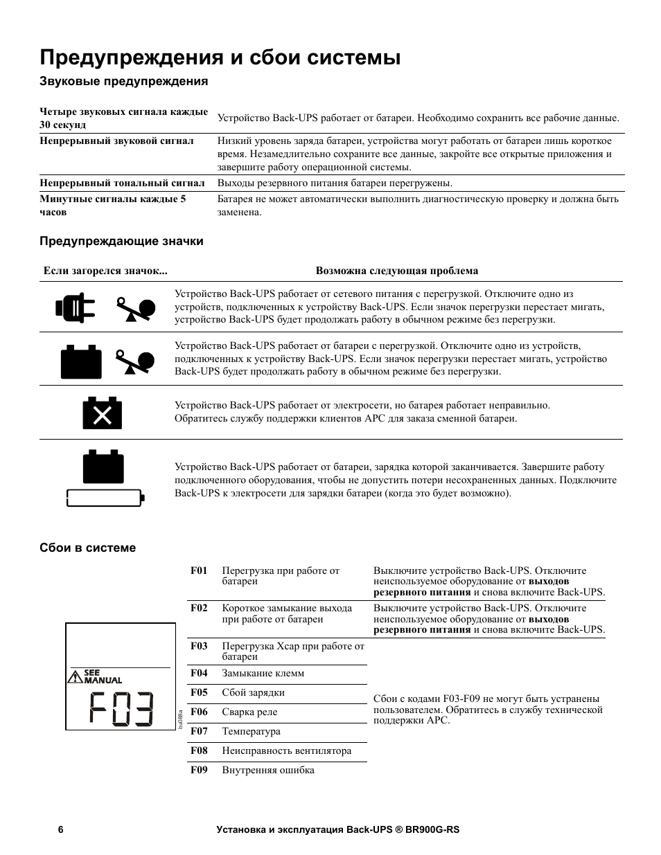
Кнопки и экран на передней панели
Для настройки устройства Back-UPS используйте три кнопки на передней панели и экран.
Передняя панель
1
Кнопка
ПРИГЛУШЕНИЯ
2
Кнопка
ПИТАНИЯ
3
Кнопка
ОТОБРАЖЕНИЯ
4
Дисплей
От сети: устройство Back-UPS осуществляет подачу питания от сети с нормативными параметрами к
подключенному оборудованию.
Функция энергосбережения: УПРАВЛЯЮЩАЯ и УПРАВЛЯЕМЫЕ розетки включены. Функция
энергосбережения активна, когда главное устройство находится в режиме сна/гибернации.
Допустимая нагрузка: процент допустимой нагрузки отображается числом светящихся секций. Каждая
секция соответствует 20% нагрузки.
Заряд батареи: уровень заряда батареи отображается числом светящихся секций. Когда светятся все пять
секций, батарея устройства Back-UPS полностью заряжена. Каждая секция соответствует 20% емкости
батареи.
Перегрузка: подключенное к устройству Back-UPS оборудование потребляет больше максимально
допустимого напряжения.
Событие: счетчик событий отображает количество событий, вызвавших переход Back-UPS в режим подачи
питания от батареи.
Вход: разъем для входного сигнала.
Выход: разъем для выходного сигнала.
Автоматическая стабилизация напряжения: устройство Back-UPS снабжено функцией повышения и
понижения (автоматической стабилизации) напряжения, сглаживающей всплески и падения сетевого
напряжения без перехода на питание от батареи. В устройстве Back-UPS также имеется функция обхода
схемы автоматической стабилизации напряжения, когда входное напряжение находится в пределах нормы.
Это помогает сберечь заряд батареи и продлить срок ее службы.
Если горит этот индикатор, устройство Back-UPS компенсирует низкое входное напряжение.
Если горит этот индикатор, устройство Back-UPS компенсирует высокое входное напряжение.
Сбои в системе: произошел внутренний сбой системы. Код сбоя будет отображаться на экране.
См. раздел «Сбои в системе» на стр. 6.
Приглушение: светящаяся линия на значке показывает, что звуковой сигнал отключен.
Необходима замена батареи: срок службы батареи почти истек. Замените батарею.
Питание от батареи: устройство Back-UPS подает на подключенное оборудование питание от батареи.
Каждые 30 секунд подается четыре звуковых сигнала.
bu
044b
Установка и эксплуатация Back-UPS ® BR900G-RS
6
Предупреждения и сбои системы
Звуковые предупреждения
Предупреждающие значки
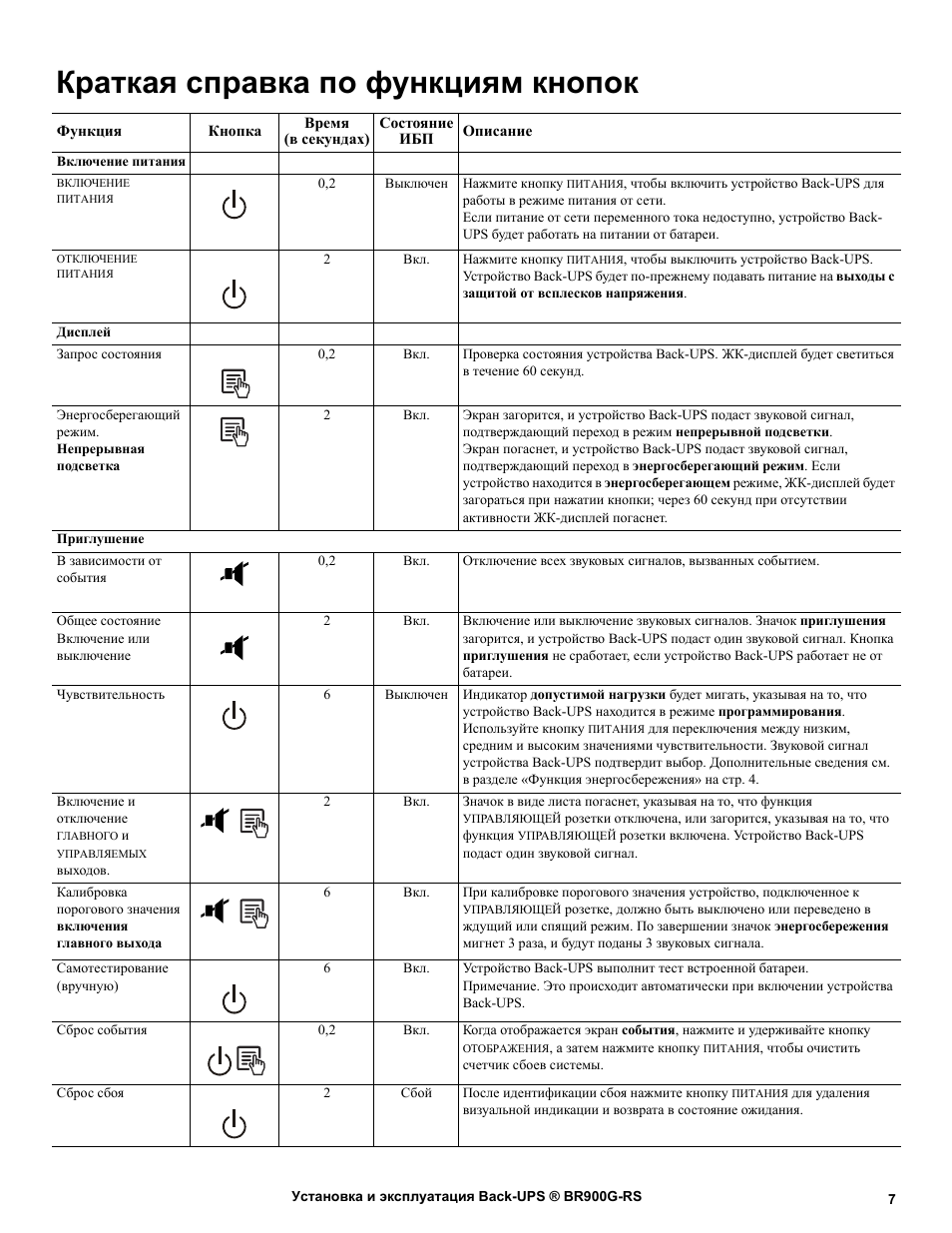
Сбои в системе
Четыре звуковых сигнала каждые
30 секунд
Устройство Back-UPS работает от батареи. Необходимо сохранить все рабочие данные.
Непрерывный звуковой сигнал
Низкий уровень заряда батареи, устройства могут работать от батареи лишь короткое
время. Незамедлительно сохраните все данные, закройте все открытые приложения и
завершите работу операционной системы.
Непрерывный тональный сигнал
Выходы резервного питания батареи перегружены.
Минутные сигналы каждые 5
часов
Батарея не может автоматически выполнить диагностическую проверку и должна быть
заменена.
Если загорелся значок…
Возможна следующая проблема
Устройство Back-UPS работает от сетевого питания с перегрузкой. Отключите одно из
устройств, подключенных к устройству Back-UPS. Если значок перегрузки перестает мигать,
устройство Back-UPS будет продолжать работу в обычном режиме без перегрузки.
Устройство Back-UPS работает от батареи с перегрузкой. Отключите одно из устройств,
подключенных к устройству Back-UPS. Если значок перегрузки перестает мигать, устройство
Back-UPS будет продолжать работу в обычном режиме без перегрузки.
Устройство Back-UPS работает от электросети, но батарея работает неправильно.
Обратитесь службу поддержки клиентов APC для заказа сменной батареи.
Устройство Back-UPS работает от батареи, зарядка которой заканчивается. Завершите работу
подключенного оборудования, чтобы не допустить потери несохраненных данных. Подключите
Back-UPS к электросети для зарядки батареи (когда это будет возможно).
F01
Перегрузка при работе от
батареи
Выключите устройство Back-UPS. Отключите
неиспользуемое оборудование от выходов
резервного питания и снова включите Back-UPS.
F02
Короткое замыкание выхода
при работе от батареи
Выключите устройство Back-UPS. Отключите
неиспользуемое оборудование от выходов
резервного питания и снова включите Back-UPS.
F03
Перегрузка Xcap при работе от
батареи
Сбои с кодами F03-F09 не могут быть устранены
пользователем. Обратитесь в службу технической
поддержки APC.
F04
Замыкание клемм
F05
Сбой зарядки
F06
Сварка реле
F07
Температура
F08
Неисправность вентилятора
F09
Внутренняя ошибка
bu
08
8a
Установка и эксплуатация Back-UPS ® BR900G-RS
7
Краткая справка по функциям кнопок
Функция
Кнопка
Время
(в секундах)
Состояние
ИБП
Описание
Включение питания
ВКЛЮЧЕНИЕ
ПИТАНИЯ
0,2
Выключен Нажмите кнопку
ПИТАНИЯ
, чтобы включить устройство Back-UPS для
работы в режиме питания от сети.
Если питание от сети переменного тока недоступно, устройство Back-
UPS будет работать на питании от батареи.
ОТКЛЮЧЕНИЕ
ПИТАНИЯ
2
Вкл.
Нажмите кнопку
ПИТАНИЯ
, чтобы выключить устройство Back-UPS.
Устройство Back-UPS будет по-прежнему подавать питание на выходы с
защитой от всплесков напряжения.
Дисплей
Запрос состояния
0,2
Вкл.
Проверка состояния устройства Back-UPS. ЖК-дисплей будет светиться
в течение 60 секунд.
Энергосберегающий
режим.
Непрерывная
подсветка
2
Вкл.
Экран загорится, и устройство Back-UPS подаст звуковой сигнал,
подтверждающий переход в режим непрерывной подсветки.
Экран погаснет, и устройство Back-UPS подаст звуковой сигнал,
подтверждающий переход в энергосберегающий режим. Если
устройство находится в энергосберегающем режиме, ЖК-дисплей будет
загораться при нажатии кнопки; через 60 секунд при отсутствии
активности ЖК-дисплей погаснет.
Приглушение
В зависимости от
события
0,2
Вкл.
Отключение всех звуковых сигналов, вызванных событием.
Общее состояние
Включение или
выключение
2
Вкл.
Включение или выключение звуковых сигналов. Значок приглушения
загорится, и устройство Back-UPS подаст один звуковой сигнал. Кнопка
приглушения не сработает, если устройство Back-UPS работает не от
батареи.
Чувствительность
6
Выключен Индикатор допустимой нагрузки будет мигать, указывая на то, что
устройство Back-UPS находится в режиме программирования.
Используйте кнопку
ПИТАНИЯ
для переключения между низким,
средним и высоким значениями чувствительности. Звуковой сигнал
устройства Back-UPS подтвердит выбор. Дополнительные сведения см.
в разделе «Функция энергосбережения» на стр. 4.
Включение и
отключение
ГЛАВНОГО
и
УПРАВЛЯЕМЫХ
выходов.
2
Вкл.
Значок в виде листа погаснет, указывая на то, что функция
УПРАВЛЯЮЩЕЙ
розетки отключена, или загорится, указывая на то, что
функция
УПРАВЛЯЮЩЕЙ
розетки включена. Устройство Back-UPS
подаст один звуковой сигнал.
Калибровка
порогового значения
включения
главного выхода
6
Вкл.
При калибровке порогового значения устройство, подключенное к
УПРАВЛЯЮЩЕЙ
розетке, должно быть выключено или переведено в
ждущий или спящий режим. По завершении значок энергосбережения
мигнет 3 раза, и будут поданы 3 звуковых сигнала.
Самотестирование
(вручную)
6
Вкл.
Устройство Back-UPS выполнит тест встроенной батареи.
Примечание. Это происходит автоматически при включении устройства
Back-UPS.
Сброс события
0,2
Вкл.
Когда отображается экран события, нажмите и удерживайте кнопку
ОТОБРАЖЕНИЯ
, а затем нажмите кнопку
ПИТАНИЯ
, чтобы очистить
счетчик сбоев системы.
Сброс сбоя
2
Сбой
После идентификации сбоя нажмите кнопку
ПИТАНИЯ
для удаления
визуальной индикации и возврата в состояние ожидания.
Установка и эксплуатация Back-UPS ® BR900G-RS
8
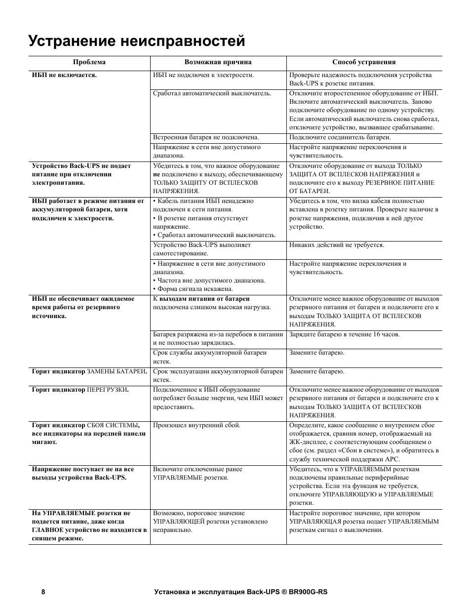
Устранение неисправностей
Проблема
Возможная причина
Способ устранения
ИБП не включается.
ИБП не подключен к электросети.
Проверьте надежность подключения устройства
Back-UPS к розетке питания.
Сработал автоматический выключатель.
Отключите второстепенное оборудование от ИБП.
Включите автоматический выключатель. Заново
подключите оборудование по одному устройству.
Если автоматический выключатель снова сработал,
отключите устройство, вызвавшее срабатывание.
Встроенная батарея не подключена.
Подключите соединитель батареи.
Напряжение в сети вне допустимого
диапазона.
Настройте напряжение переключения и
чувствительность.
Устройство Back-UPS не подает
питание при отключении
электропитания.
Убедитесь в том, что важное оборудование
не подключено к выходу, обеспечивающему
ТОЛЬКО
ЗАЩИТУ
ОТ
ВСПЛЕСКОВ
НАПРЯЖЕНИЯ
.
Отключите оборудование от выхода Т
ОЛЬКО
ЗАЩИТА
ОТ
ВСПЛЕСКОВ
НАПРЯЖЕНИЯ
и
подключите его к выходу Р
ЕЗЕРВНОЕ
ПИТАНИЕ
ОТ
БАТАРЕИ
.
ИБП работает в режиме питания от
аккумуляторной батареи, хотя
подключен к электросети.
• Кабель питания ИБП ненадежно
подключен к сети питания.
• В розетке питания отсутствует
напряжение.
• Сработал автоматический выключатель.
Убедитесь в том, что вилка кабеля полностью
вставлена в розетку питания. Проверьте наличие в
розетке напряжения, подключив к ней другое
устройство.
Устройство Back-UPS выполняет
самотестирование.
Никаких действий не требуется.
• Напряжение в сети вне допустимого
диапазона.
• Частота вне допустимого диапазона.
• Форма сигнала искажена.
Настройте напряжение переключения и
чувствительность.
ИБП не обеспечивает ожидаемое
время работы от резервного
источника.
К выходам питания от батареи
подключена слишком высокая нагрузка.
Отключите менее важное оборудование от выходов
резервного питания от батареи и подключите его к
выходам Т
ОЛЬКО
ЗАЩИТА
ОТ
ВСПЛЕСКОВ
НАПРЯЖЕНИЯ
.
Батарея разряжена из-за перебоев в питании
и не полностью зарядилась.
Зарядите батарею в течение 16 часов.
Срок службы аккумуляторной батареи
истек.
Замените батарею.
Горит индикатор
ЗАМЕНЫ
БАТАРЕИ
. Срок эксплуатации аккумуляторной батареи
истек.
Замените батарею.
Горит индикатор
ПЕРЕГРУЗКИ
.
Подключенное к ИБП оборудование
потребляет больше энергии, чем ИБП может
предоставить.
Отключите менее важное оборудование от выходов
резервного питания от батареи и подключите его к
выходам Т
ОЛЬКО
ЗАЩИТА
ОТ
ВСПЛЕСКОВ
НАПРЯЖЕНИЯ
.
Горит индикатор
СБОЯ
СИСТЕМЫ
,
все индикаторы на передней панели
мигают.
Произошел внутренний сбой.
Определите, какое сообщение о внутреннем сбое
отображается, сравнив номер, отображаемый на
ЖК-дисплее, с соответствующим сообщением о
сбое (см. раздел «Сбои в системе»), и обратитесь в
службу технической поддержки APC.
Напряжение поступает не на все
выходы устройства Back-UPS.
Включите отключенные ранее
УПРАВЛЯЕМЫЕ
розетки.
Убедитесь, что к
УПРАВЛЯЕМЫМ
розеткам
подключены правильные периферийные
устройства. Если эта функция не требуется,
отключите У
ПРАВЛЯЮЩУЮ
и
УПРАВЛЯЕМЫЕ
розетки.
На
УПРАВЛЯЕМЫЕ
розетки не
подается питание, даже когда
ГЛАВНОЕ
устройство не находится в
спящем режиме.
Возможно, пороговое значение
У
ПРАВЛЯЮЩЕЙ
розетки установлено
неправильно.
Настройте пороговое значение, при котором
У
ПРАВЛЯЮЩАЯ
розетка подает
УПРАВЛЯЕМЫМ
розеткам сигнал о выключении.
Установка и эксплуатация Back-UPS ® BR900G-RS
9
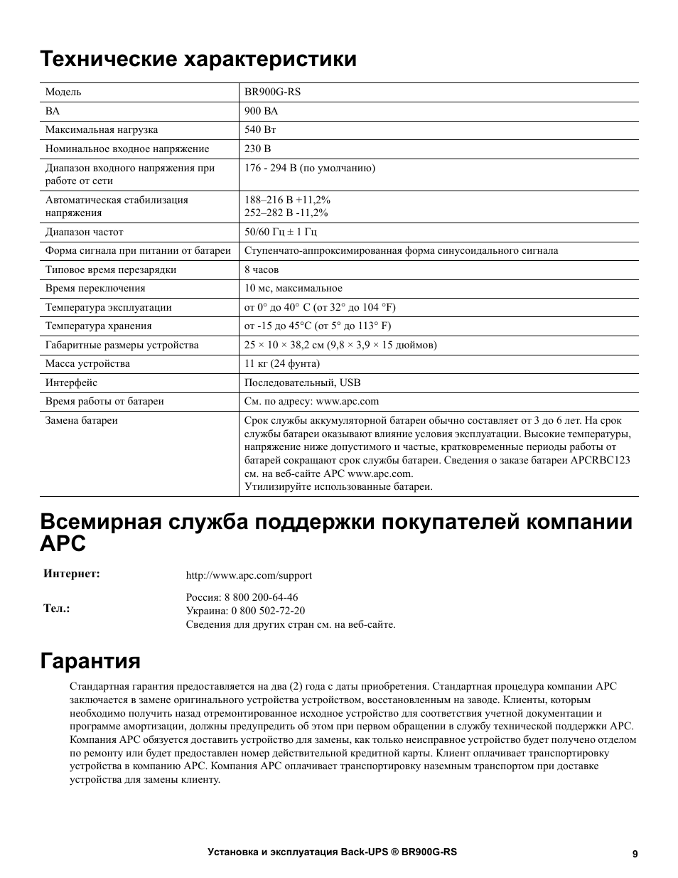
Технические характеристики
t
Всемирная служба поддержки покупателей компании
APC
Гарантия
Стандартная гарантия предоставляется на два (2) года с даты приобретения. Стандартная процедура компании APC
заключается в замене оригинального устройства устройством, восстановленным на заводе. Клиенты, которым
необходимо получить назад отремонтированное исходное устройство для соответствия учетной документации и
программе амортизации, должны предупредить об этом при первом обращении в службу технической поддержки APC.
Компания APC обязуется доставить устройство для замены, как только неисправное устройство будет получено отделом
по ремонту или будет предоставлен номер действительной кредитной карты. Клиент оплачивает транспортировку
устройства в компанию APC. Компания APC оплачивает транспортировку наземным транспортом при доставке
устройства для замены клиенту.
Модель
BR900G-RS
ВА
900 ВА
Максимальная нагрузка
540 Вт
Номинальное входное напряжение
230 В
Диапазон входного напряжения при
работе от сети
176 — 294 В (по умолчанию)
Автоматическая стабилизация
напряжения
188–216 В +11,2%
252–282 В -11,2%
Диапазон частот
50/60 Гц ± 1 Гц
Форма сигнала при питании от батареи
Ступенчато-аппроксимированная форма синусоидального сигнала
Типовое время перезарядки
8 часов
Время переключения
10 мс, максимальное
Температура эксплуатации
от 0° до 40°
C (от 32° до 104 °F)
Температура хранения
от -15 до 45°C (от 5° до 113° F)
Габаритные размеры устройства
25 Ч 10 Ч 38,2 см (9,8 Ч 3,9 Ч 15 дюймов)
Масса устройства
11 кг (24 фунта)
Интерфейс
Последовательный, USB
Время работы от батареи
См. по адресу: www.apc.com
Замена батареи
Срок службы аккумуляторной батареи обычно составляет от 3 до 6 лет. На срок
службы батареи оказывают влияние условия эксплуатации. Высокие температуры,
напряжение ниже допустимого и частые, кратковременные периоды работы от
батарей сокращают срок службы батареи. Сведения о заказе батареи APCRBC123
см. на веб-сайте APC www.apc.com.
Утилизируйте использованные батареи.
Интернет:
http://www.apc.com/support
Тел.:
Россия: 8 800 200-64-46
Украина: 0 800 502-72-20
Сведения для других стран см. на веб-сайте.
© APC by Schneider Electric, 2012 г. APC, эмблема APC, Back-UPS и PowerChute
являются собственностью компании Schneider Electric Industries S.A.S., American Power
Conversion Corporation или ее дочерних компаний. Другие товарные знаки являются
собственностью соответствующих владельцев.
RU 990-4711
03/2012
Сервисное обслуживание
В случае необходимости технического обслуживания не возвращайте его продавцу. Вместо этого
выполните следующие операции.
1. Обратитесь к разделу Поиск и устранение неисправностей в данном руководстве для устранения
наиболее часто возникающих неполадок.
2. Если проблема не устраняется, обратитесь в службу технической поддержки компании APC,
воспользовавшись сайтом компании: www.apc.com.
a. Укажите номер модели и серийный номер, а также дату приобретения. Номер
модели и серийный номер указаны на задней панели устройства, в некоторых
моделях они отображаются на ЖК-дисплее.
b. Позвоните в службу технической поддержки APC, и сотрудник компании
попытается решить проблему по телефону. Если проблема не решается,
сотрудник сообщит вам номер возврата товара (RMA).
c. Если срок гарантийного обслуживания блока не истек, ремонт выполняется
бесплатно.
d. Условия сервисного обслуживания и возврата могут варьироваться в зависимости
от страны. Условия для страны вашего проживания см. на сайте APC.
3. Во избежание повреждений при транспортировке упаковывайте устройство должным образом. Не
допускается использовать для упаковки пеноматериал. Гарантийные обязательства не
распространяются на повреждения оборудования, возникшие при его транспортировке.
Примечание. При отправке по США или в США перед отправкой ОТКЛЮЧИТЕ
АККУМУЛЯТОРНУЮ БАТАРЕЮ в соответствии с требованиями Министерства транспорта
США и IATA (Международная ассоциация воздушного транспорта). Внутренние батареи можно
не извлекать из ИБП.
4. Напишите номер возврат товара (RMA) на наружной стороне упаковки.
5. Отправьте устройство застрахованной предварительно оплаченной посылкой по адресу, указанному
сотрудником службы технической поддержки.

03:20
ИБП APC Back-UPS Pro 1500 с AVR, ЖК-экраном и портом для управления и мониторинга
04:47
Обзор ИБП APC Back-UPS Pro 900 в 4k
04:39
Недорогой ИБП APC Back-UPS Pro 900 (BR900GI)
04:18
APC Back-UPS Pro 900. Малое время работы от новых АКБ, 3 замены батарей за 2 года
09:39
40 минут без розетки! 3d принтер на ИБП со стабилизатором Pro BR900GI APC by Schneider Electric
05:54
APC Back-UPS Pro BR1300MI — зачем нужен мощный ИБП?
09:56
Обзор и мнение о ИБП для ПК — APC BACK-UPS PRO 1500 (BR1500G-RS)
08:15
APC BACK-UPS BR1500G-RS: ИБП БЕЗ КОМПРОМИССОВ
Нажмите на кнопку для помощи
Table of Contents
- APC BR900G-RS Back-UPS
- Safety
- Important Safety Messages
- Connect the Battery
- PowerChute Personal Edition Software
- Connect the Equipment
- Operation
- Front Panel Buttons and Display
- Alerts and System Events
- Function Quick-Reference
- Troubleshooting
- Specifications
- Warranty
- References
- Read User Manual Online (PDF format)
- Download This Manual (PDF format)
APC BR900G-RS Back-UPS
Inventory

Safety
This unit is intended for indoor use only. Do not operate this unit in direct
sunlight, in contact with fluids, or where there is excessive dust or
humidity.
Important Safety Messages
SAVE THESE INSTRUCTIONS – This manual contains important instructions that
should be followed during installation and maintenance of the UPS and
batteries.
- This UPS is intended for indoor use only.
- Do not operate this UPS in direct sunlight, in contact with fluids, or where there is excessive dust or humidity.
- Be sure the air vents on the UPS are not blocked. Allow adequate space for proper ventilation.
- The battery typically lasts for three to five years. Environmental factors impact battery life. Elevated ambient temperatures, poor quality AC power, and frequent short duration discharges will shorten battery life.
- Connect the UPS power cable directly to a wall outlet. Do not use surge protectors or extension cords
CAUTION
RISK OF HYDROGEN SULPHIDE GAS AND EXCESSIVE SMOKE
- Replace the battery at least every 5 years or at the end of its service life, whichever is earlier.
- Replace the battery immediately when the UPS indicates battery replacement is necessary.
- Replace batteries with the same number and type of batteries as originally installed in the equipment.
- Replace the battery immediately when the UPS indicates a battery over-temperature condition, or when there is evidence of electrolyte leakage. Power off the UPS, unplug it from the AC input, and disconnect the batteries. Do not operate the UPS until the batteries have been replaced.
- Failure to follow these instructions can result in minor or moderate injury and equipment damage
For the recycling battery information, please go to
apc.com/recycle
- CAUTION : Servicing of batteries should be performed or supervised by personnel knowledgeable about batteries and the required precautions.
- CAUTION: Do not dispose of batteries in a fire. The batteries may explode.
- CAUTION : Do not open or mutilate batteries. Released material is harmful to the skin and eyes. It may be toxic.
- CAUTION : Before replacing batteries, remove conductive jewelry such as chains, wrist watches, and rings. High energy through conductive materials could cause severe burns.
- CAUTION : Failed batteries can reach temperatures that exceed the burn thresholds for touchable surfaces.CAUTION: A battery can present a risk of electrical shock and high short-circuit current. The following precautions should be observed when working on batteries:
- Disconnect the charging source prior to connecting or disconnecting battery terminals.
- Do not wear any metal objects including watches and rings.
- Do not lay tools or metal parts on top of batteries.
- Use tools with insulated handles.
- Wear rubber gloves and boots.
- Determine if battery is either intentionally or inadvertently grounded. Contact with any part of a grounded battery can result in electric shock and burns by high short-circuit current. The risk of such hazards can be reduced if grounds are removed during installation and maintenance by a skilled person.
- This manual can be downloaded from APC by Schneider Electric Website www.apc.com
Connect the Battery

PowerChute Personal Edition Software
-
Overview
- PowerChute Personal Edition Software allows you to use your computer to access additional power protection and management features of the Back-UPS.
-
Using PowerChute, you can:
- Preserve work in progress during a power outage by putting your computer into Hibernate mode. When the power returns, the computer will appear exactly as it did before the power outage.
- Configure the Back-UPS management features, such as power-saving outlets, shutdown parameters, audible alarms, and more.
- Monitor and view the status of the Back-UPS, including the estimated runtime, power consumption, power event history, and more.
Available features will vary by Back-UPS model and operating system.
If you choose not to install PowerChute, the Back-UPS will still provide
backup power and power protection to connected equipment. However, you will
only be able to configure a limited number of features using the display
interface.
-
Compatibility
- PowerChute is compatible with Windows operating systems only. For a detailed list of supported operating systems, go to www.apc.com, select Software & Firmware.
- For Mac operating systems, we recommend using the native shutdown application (within System Preferences) which recognizes your battery backup and allows you to configure shutdown of your system during power outages. To access this application, connect a USB cable from the Back-UPS DATA PORT (POWERCHUTE PORT) to a USB port on your computer, and see the documentation provided with your computer.
-
Installation
- Use the USB cable to connect the USB and Serial port on the UPS to the USB port on your computer. Download PowerChute™
- Personal Edition Software from www.apc.com/pcpe. Select the appropriate operating system and follow directions to download and install the software.
Connect the Equipment

Battery Backup and Surge Protected outlets
- When the Back-UPS is receiving input power, the Surge Protection only outlets and the Battery Backup with Surge Protection outlets will supply power to connected equipment. During a power outage or other AC problems, only the Battery Backup outlets receive power for a limited time from the Back-UPS.
- Connect equipment such as printers, FAX machines, scanners, or other peripherals that do not need battery backup power to the Surge Protection Only outlets.
- These outlets provide full time protection from surges even if the Back-UPS is switched off.
Master and Controlled outlets
- To conserve electricity, when the device connected to Master Outlet goes into Sleep or Standby mode, or turns off, the Controlled by Master device(s) will shut down as well, saving electricity.
- Connect a master device, such as a desktop computer or audio/visual receiver to the Master outlet. Connect peripheral devices such as a printer, speakers, or a scanner to the Controlled by Master outlets.
| USB and Serial Data port| To use PowerChute software, connect a USB
cable, to the USB or serial port.
—|—|—
| Telephone Cable Surge- protected ports| Connect one end of a
DSL/Modem/FAX/Phone cable to a telephone wall outlet and the other end to the
IN port on the Back-UPS. Connect one end of a DSL/Modem/FAX/Phone cable to a
modem, FAX
| | machine or telephone and the other end to the OUT port on the Back-UPS.
| Surge Protection outlet, Controlled by Master outlet| This outlet
provides surge protection during a power outage. This outlet will disconnect
from AC power during a power outage, or in the event that the Master outlet
goes into Sleep mode.
| Surge Protection outlets| These outlets provide full-time protection
for connected equipment from power surges when the Back- UPS is turned on or
off. The Surge Protection outlets do not provide battery backup to connected
equipment. Connect a printer, scanner or other noncritical devices that do not
require battery backup protection.
| AC Power Cable| Use this cable to connect the Back-UPS to AC power.
| Battery Backup outlets with Surge Protection| These outlets provide
battery backup power to connected equipment for a limited period of time
during power outages and voltage fluctuations. The Battery Backup + Surge
Protection outlets provide battery power to connected equipment only when the
Back-UPS is turned on.
Connect essential equipment such as a computer, computer monitor, modem or
other data sensitive devices to these outlets. Do not connect aquarium
equipment, laser printers, paper shredders, sump pumps, or fans to these
outlets as the modified sine wave output of the Back-UPS may cause these
devices to experience a decrease in performance. Do not connect surge
protectors or extension cords to these outlets.
| Battery Backup, Controlled by Master outlet with Surge
Protection
| This outlet provides surge protection for the connected device. To conserve
energy the Controlled by Master outlets will disconnect from AC power whenever
the device plugged into the MASTER outlet
is turned off or goes into Standby or Hibernation mode.
| Master outlet| Connect the master device to this outlet, in most
cases, this will be the main computer.
In addition to providing battery backup power and surge protection, this
outlet will signal the Controlled by Master outlets to disconnect from AC
power when the master device is either turned off
or goes into Standby or Hibernation mode.
| Gigabit Ethernet surge-protected ports| Use an Ethernet cable to
connect a modem or router to the IN port, and a computer to the OUT port.
| Circuit breaker| Press the circuit breaker reset button after an
overload condition or a short circuit has occurred causing the circuit breaker
to trip. This action can be taken when the Back-UPS is operating on utility or
battery power.
Operation
Power Saving Feature
-
This Back-UPS is equipped with power saving outlets that conserve electricity. Configure the Back-UPS to recognize a Master device, such as a computer or an A/V receiver, and Controlled by master peripheral devices, such as a printer, speakers, or a scanner. When the Master device goes into Standby or Hibernation mode, or is turned off, the Controlled by Master device(s) will be turned off.
-
The Back-UPS ships with this Power Saving feature DISABLED. To configure this feature, follow the instructions below or use PowerChute software.
Notes : Devices that provide network services (such as routers, modems,
or wireless printers) should not be plugged into the Controlled outlets. The
Back-UPS ships with this Power-Saving feature DISABLED. If you wish to use
this feature, follow the instructions below: -
Enable the Power Saving Controlled outlets. Press and hold MUTE and DISPLAY buttons simultaneously for two seconds. The Back-UPS will beep to indicate the feature is enabled. The leaf icon on the display will illuminate.
-
Disable the Power Saving Controlled outlets. Press and hold MUTE and DISPLAY buttons simultaneously for two seconds. The Back-UPS will beep to indicate the feature is disabled. The leaf icon on the display will extinguish.
-
Setting the threshold. The amount of power used by a device in Standby or Hibernation mode varies dependant on the connected device. If the Controlled outlets do not turn off when the Master device is in Standby or Hibernation mode, it may be necessary to adjust the threshold at which the MASTER outlet signals the CONTROLLED outlets to shut down.

- Be sure a master device is connected to the MASTER outlet. Place that device into Standby or Hibernation mode, or turn it off.
- Press MUTE and DISPLAY buttons simultaneously and hold for six seconds, until the leaf icon flashes three times and the Back-UPS beeps three times.
- The Back-UPS will now recognize and save the threshold level as the new threshold setting for the master device.

Power-Saving LCD Screen
The display interface can be configured to remain continuously illuminated or
to extinguish after a period of inactivity to save electricity.
- Continuous Illumination mode: Press and hold DISPLAY button for two seconds. The display will illuminate and the Back-UPS will beep to confirm Continuous Illumination mode is activated.
- Power Saving mode: Press and hold DISPLAY button for two seconds. The display will extinguish and the Back-UPS will beep to confirm Power Saving mode is activated. While in Power Saving mode, the display will illuminate if a button is pressed, it will extinguish after 60 seconds of inactivity.
Back-UPS Sensitivity Settings
The Back-UPS detects and reacts to line voltage distortions by transferring to
battery backup power to protect connected equipment. In situations where
either the Back-UPS or the connected equipment is too sensitive for the input
voltage level it is necessary to adjust the transfer voltage.
- Connect the Back-UPS to a utility power source. Be sure the Back-UPS is turned off.
- Press and hold the POWER button for six seconds. The load capacity bar will flash on and off, to indicate the Back-UPS is in Program mode.
- Press the POWER button again to scroll through the menu options. The Back-UPS will beep to confirm the selection. Refer to the table for an explanation of the transfer voltage sensitivity levels.
- Use this setting with equipment that is less sensitive to fluctuations in voltage or waveform distortions.
- Use this setting under normal operating conditions.
- Use this setting when connected equipment is sensitive to any minor fluctuations in voltage or waveform distortions.
Front Panel Buttons and Display
Use the three buttons on the front panel of the Back-UPS and the display to
configure the Back-UPS.
Front panel

- MUTE button
- POWER button
- DISPLAY button
- Display


Alerts and System Events
Audible Alerts

Events Icons

System Events

Function Quick-Reference
Function| Button| Timing (seconds)| UPS
Status
| Description
—|—|—|—|—
Power
POWER ON| ****| 0.2| Off| Press the POWER ON/OFF button to turn on the Back-
UPS and operate on AC power.
If AC input power is not available the Back-UPS will operate on
battery power.
—|—|—|—|—
POWER OFF| ****| 2| On| Press the POWER ON/OFF button to turn off the Back-
UPS.
The Back-UPS will continue to provide surge protection to the
Surge Protection outlets.
Display
Status Inquiry| | 0.2| On| Verify the status or condition of the Back-
UPS. The LCD will illuminate for 60 seconds.
—|—|—|—|—
Power-Saving| | 2| On| The LCD will illuminate and the Back-UPS will
beep to confirm
mode:| | | Continuous Illumination mode is activated.
Continuous| | | The LCD will extinguish and the Back-UPS will beep to
confirm
Illumination| | | that
| | | Power-Saving mode is activated. While in Power-Saving mode,
| | | the LCD will illuminate if a button is pressed, then extinguish after
| | | 60 seconds of no activity.
Mute
Event Specific| | 0.2| On| Disable any audible alarms caused by an
event.
—|—|—|—|—
General Status Enable/Disable| | 2| On| Enable or disable the audible
alarms. The Mute icon will illuminate and the Back-UPS will beep one time.
The Mute feature will not
activate unless the Back-UPS is operating on battery power.
Sensitivity| **| 6| Off| The Load Capacity icon will flash to indicate
the Back-UPS is in Program** mode. Use the POWER ON/OFF button to scroll
through and select Low, Medium, and High sensitivity levels. The Back- UPS
will beep to confirm the selection. Refer to “Power Saving
Feature” on page 4 for details.
MASTER / CONTROLLED
outlet Enable/ Disable
| ****
| 2| On| The leaf icon will extinguish to indicate the MASTER outlet feature
is disabled or illuminate to indicate the MASTER outlet feature is enabled.
The Back-UPS will beep once.
Master/Enable threshold calibration| ****
| 6| On| While calibrating the threshold setting, the device connected to the
MASTER outlet should be turned off or placed in Standby or Sleep mode. Once
the threshold setting has been selected the Power- Saving icon will flash
3 times and beep 3 times.
Self-Test (manual)| ****| 6| On| The Back-UPS will run a test of the
internal battery.
Note: This will happen automatically when the Back-UPS is turned on.
Event Reset| **| 0.2| On| When the Event screen is visible, press
and hold DISPLAY, then press the POWER button to clear the AC event counter.
Status Reset| **| 2| Event| After an event has been identified, press
the POWER ON/OFF button to remove the visual indication and return to standby
status.
Troubleshooting
| Problem | Possible Cause | Corrective Action |
|---|---|---|
| Back-UPS will not turn on. | The Back-UPS is not connected to AC |
power.
| Be sure the Back-UPS is securely connected to a
AC outlet.
The circuit breaker has been tripped.| Disconnect non-essential equipment from
the Back-UPS. Reset the circuit breaker. Re-connect equipment one item at a
time. If the circuit breaker trips again, disconnect the device that
caused the event.
The internal battery is not connected.| Connect the battery.
The AC input voltage is out of range.| Adjust the transfer voltage and
sensitivity range.
The Back-UPS does not provide power during a AC power outage.| Besure
that essential equipment is not
plugged into a SURGE ONLY outlet.
| Disconnect equipment from the SURGE ONLY
outlet and connect to a BATTERY BACKUP outlet.
The Back-UPS is operating on battery power, while connected to AC power.|
• The Back-UPS power cable is not securely connected to the wall outlet.
• The wall outlet is no longer receiving AC power.
• The circuit breaker has been tripped.
| Be sure the plug is fully inserted into the wall outlet. Be sure the wall
outlet is receiving AC power by checking it with another device.
The Back-UPS is running an automatic
self test.
| No action is necessary.
• The AC input voltage is out of range.
• The frequency is out of range.
• The waveform is distorted.
| Adjust the transfer voltage and sensitivity range.
The Back-UPS does not provide the expected amount of backup time.|
Battery Backup outlets may be experiencing an overload condition.|
Disconnect non-essential equipment from the Battery Backup outlets and connect
the equipment to SURGE ONLY outlets.
The battery was recently discharged due to
a power outage and has not fully recharged.
| Charge the battery cartridge for 16 hours.
The battery has reached the end of its
service life.
| Replace the battery.
The REPLACE BATTERY indicator
is illuminated.
| The battery has reached the end of its
useful life.
| Replace the battery.
The OVERLOAD indicator is illuminated.| The equipment connected to
the Back- UPS is drawing more power than the
Back-UPS can provide.
| Disconnect non-essential equipment from the Battery Backup outlets and
connect the
equipment to SURGE ONLY outlets.
The SYSTEM EVENT indicator is illuminated, all the front panel
indicators are flashing.| There is an internal error.| Determine which
internal error message is displayed by matching the number displayed on the
LCD with the corresponding Error Message (see System Error) and contact APC
Technical Support.
The Back-UPS is not supplying power to all of the outlets.| Power to the
CONTROLLED outlets has intentionally been turned off.| Confirm that the
correct peripherals are connected to CONTROLLED outlets. If this feature is
not desired, disable the
Power-Saving MASTER and CONTROLLED
outlets.
The C ONTROLLED outlets are not supplying power, even though the
M ASTER device is not in sleep
mode.
| The MASTER outlet threshold may be incorrectly set.| Adjust the threshold
when the MASTER outlet signals the CONTROLLED outlets to shut down.
Specifications
| Model | BR900G-RS |
|---|---|
| VA | 900 VA |
| Maximum Load | 540 W |
| Nominal Input Voltage | 230 V |
| Online Input Voltage Range | 176 V to 294 V |
| Automatic Voltage Regulation | 188 V-216 V +11.2% |
252 V-282 V -11.2%
Frequency Range| 50/60 Hz ± 1 Hz
On-battery wave shape| Step-approximated sine-wave
Typical Recharge Time| 8 hours
Transfer Time| 10 ms, maximum
Operating Temperature| 0° to 40° C (32° to 104°F)
Storage Temperature| -15° to 45° C (5° to 113° F)
Unit Dimensions| 25 × 10 × 38.2 cm (9.8 × 3.9 × 15 in)
Unit Weight| 11 kg (24 lbs)
Interface| Serial, USB
On-Battery Runtime| Go to: www.apc.com
Replacement Battery| The battery cartridge typically lasts 3 to 6 years.
Environmental factors impact battery life. High temperatures, poor quality A/C
power, and frequent, short deration discharges will shorten battery life. To
order replacement battery cartridge APCRBC123, refer to the APC Web site,
www.apc.com.
Recycle used battery cartridges.
Humidity| 0 to 95% relative humidity, non-condensing
Pollution degree| 2
Overvoltage category| II
Applicable power grid power
distribution system
| TN Power system
Applicable standard| IEC 62040-1
International Protection Code| IP20
APC Customer Support Worldwide
- Internet http://www.apc.com/support
- Telephone
- Russia: 8 800 200-64-46
- Ukraine: 0 800 502-72-20
- Check Web site listings for other countries
Warranty
The standard warranty is two (2) years from the date of purchase. The APC by
Schneider Electric standard procedure is to replace the original unit with a
factory reconditioned unit. On first contact with APC Technical Support the
customer must advise the representative if the unit has as an asset tag and
must returned to the customer after repairs are completed. APC by Schneider
Electric will ship the replacement unit once the defective unit has been
received by the repair department, or cross ship upon the receipt of a valid
credit card number. The customer pays for shipping the unit to APC by
Schneider Electric. APC by Schneider Electric pays ground freight
transportation costs to ship the replacement unit to the customer.
Service
If the unit requires service, do not return it to the dealer. Follow these
steps:
-
Review the Troubleshooting section of the manual to eliminate common problems.
-
If the problem persists, contact APC Customer Support through the Web site, www.apc.com.
-
Note the model number and serial number and the date of purchase. The model and serial numbers are located on the rear panel of the unit and are available through the LCD display on select models.
-
Call APC Customer Support and a technician will attempt to solve the problem over the phone. If this is not possible, the technician will issue a Returned Material Authorization Number (RMA#).
-
If the unit is under warranty, the repairs are free.
-
Service procedures and returns may vary internationally. Refer to the APC Web site for country specific instructions.
-
Pack the unit properly to avoid damage in transit. Never use foam beads for packaging. Damage sustained in transit is not covered under warranty.
Note : When shipping within the United States, or to the United States
always DISCONNECT A UPS BATTERY before shipping in compliance with U.S.
Department of Transportation (DOT) and IATA regulations. The internal
batteries may remain in the UPS. -
Write the RMA# provided by Customer Support on the outside of the package.
-
Return the unit by insured, pre-paid carrier to the address provided by Customer Support
© 2022 APC by Schneider Electric. APC, the APC logo, Back-UPS and PowerChute
are owned by Schneider Electric Industries S.A.S., American Power Conversion
Corporation, or their affiliated companies. All other trademarks are property
of their respective owners.
References
- APC, a flagship brand of Schneider Electric — APC USA
- APC, a flagship brand of Schneider Electric — APC USA
Read User Manual Online (PDF format)
Read User Manual Online (PDF format) >>
Download This Manual (PDF format)
Download this manual >>
Installation and Operation Manual Back-UPS BR900G-RS
Important Safety Messages SAVE THESE INSTRUCTIONS — This manual contains important instructions that should be followed during installation and maintenance of the UPS and batteries.
This UPS is intended for indoor use only. Do not operate this UPS in direct sunlight, in contact with fluids, or where there is excessive dust or humidity. Be sure the air vents on the UPS are not blocked. Allow adequate space for proper ventilation. The battery typically lasts for three to five years. Environmental factors impact battery life. Elevated ambient temperatures, poor
quality AC power, and frequent short duration discharges will shorten battery life. Connect the UPS power cable directly to a wall outlet. Do not use surge protectors or extension cords.
For the recycling battery information, please go to apc.com/recycle
CAUTION: Servicing of batteries should be performed or supervised by personnel knowledgeable about batteries and the required precautions.
CAUTION: Do not dispose of batteries in a fire. The batteries may explode. CAUTION: Do not open or mutilate batteries. Released material is harmful to the skin and eyes. It may be toxic. CAUTION: Before replacing batteries, remove conductive jewelry such as chains, wrist watches, and rings. High energy through
conductive materials could cause severe burns. CAUTION: Failed batteries can reach temperatures that exceed the burn thresholds for touchable surfaces.CAUTION: A battery
can present a risk of electrical shock and high short-circuit current. The following precautions should be observed when working on batteries:
Disconnect the charging source prior to connecting or disconnecting battery terminals. Do not wear any metal objects including watches and rings. Do not lay tools or metal parts on top of batteries. Use tools with insulated handles. Wear rubber gloves and boots.
Inventory Safety
This unit is intended for indoor use only. Do not operate this unit in direct sunlight, in contact with fluids, or where there is excessive dust or humidity.
CAUTION RISK OF HYDROGEN SULPHIDE GAS AND EXCESSIVE SMOKE Replace the battery at least every 5 years or at the end of its service life, whichever is earlier. Replace the battery immediately when the UPS indicates battery replacement is necessary. Replace batteries with the same number and type of batteries as originally installed in the equipment. Replace the battery immediately when the UPS indicates a battery over-temperature condition, or when
there is evidence of electrolyte leakage. Power off the UPS, unplug it from the AC input, and disconnect the batteries. Do not operate the UPS until the batteries have been replaced.
Failure to follow these instructions can result in minor or moderate injury and equipment damage.
bu 00
1a
Determine if battery is either intentionally or inadvertently grounded. Contact with any part of a grounded battery can result in electric shock and burns by high short-circuit current. The risk of such hazards can be reduced if grounds are removed during installation and maintenance by a skilled person.
This manual can be downloaded from APC by Schneider Electric Website www.apc.com.
Connect the Battery
PowerChute Personal Edition Software Overview
PowerChute Personal Edition Software allows you to use your computer to access additional power protection and management features of the Back-UPS.
Using PowerChute, you can:
Preserve work in progress during a power outage by putting your computer into Hibernate mode. When the power returns, the computer will appear exactly as it did before the power outage.
Configure the Back-UPS management features, such as power-saving outlets, shutdown parameters, audible alarms, and more. Monitor and view the status of the Back-UPS, including the estimated runtime, power consumption, power event history, and
more. Available features will vary by Back-UPS model and operating system.
If you choose not to install PowerChute, the Back-UPS will still provide backup power and power protection to connected equipment. However, you will only be able to configure a limited number of features using the display interface.
Compatibility PowerChute is compatible with Windows operating systems only. For a detailed list of supported operating systems, go to www.apc.com, select Software & Firmware.
For Mac operating systems, we recommend using the native shutdown application (within System Preferences) which recognizes your battery backup and allows you to configure shutdown of your system during power outages. To access this application, connect a USB cable from the Back-UPS DATA PORT (POWERCHUTE PORT) to a USB port on your computer, and see the documentation provided with your computer.
Installation Use the USB cable to connect the USB and Serial port on the UPS to the USB port on your computer. Download PowerChute Personal Edition Software from www.apc.com/pcpe. Select the appropriate operating system and follow directions to download and install the software.
Charge the battery for at least 16 hours before use
bu 05
5a
bu 05
7a bu 05
9a
bu 05
8a
bu 06
0a
Back-UPS BR900G-RS Installation and Operation2
Connect the Equipment Battery Backup and Surge Protected outlets
When the Back-UPS is receiving input power, the Surge Protection only outlets and the Battery Backup with Surge Protection outlets will supply power to connected equipment. During a power outage or other AC problems, only the Battery Backup outlets receive power for a limited time from the Back-UPS.
Connect equipment such as printers, FAX machines, scanners, or other peripherals that do not need battery backup power to the Surge Protection Only outlets. These outlets provide full time protection from surges even if the Back-UPS is switched off.
Master and Controlled outlets To conserve electricity, when the device connected to Master Outlet goes into Sleep or Standby mode, or turns off, the Controlled by Master device(s) will shut down as well, saving electricity.
Connect a master device, such as a desktop computer or audio/visual receiver to the Master outlet. Connect peripheral devices such as a printer, speakers, or a scanner to the Controlled by Master outlets.
USB and Serial Data port To use PowerChute software, connect a USB cable, to the USB or serial port.
Telephone Cable Surge- protected ports
Connect one end of a DSL/Modem/FAX/Phone cable to a telephone wall outlet and the other end to the IN port on the Back-UPS. Connect one end of a DSL/Modem/FAX/Phone cable to a modem, FAX machine or telephone and the other end to the OUT port on the Back-UPS.
Surge Protection outlet, Controlled by Master outlet
This outlet provides surge protection during a power outage. This outlet will disconnect from AC power during a power outage, or in the event that the Master outlet goes into Sleep mode.
Surge Protection outlets These outlets provide full-time protection for connected equipment from power surges when the Back- UPS is turned on or off. The Surge Protection outlets do not provide battery backup to connected equipment. Connect a printer, scanner or other noncritical devices that do not require battery backup protection.
AC Power Cable Use this cable to connect the Back-UPS to AC power.
Battery Backup outlets with Surge Protection
These outlets provide battery backup power to connected equipment for a limited period of time during power outages and voltage fluctuations. The Battery Backup + Surge Protection outlets provide battery power to connected equipment only when the Back-UPS is turned on. Connect essential equipment such as a computer, computer monitor, modem or other data sensitive devices to these outlets. Do not connect aquarium equipment, laser printers, paper shredders, sump pumps, or fans to these outlets as the modified sine wave output of the Back-UPS may cause these devices to experience a decrease in performance. Do not connect surge protectors or extension cords to these outlets.
Battery Backup, Controlled by Master outlet with Surge Protection
This outlet provides surge protection for the connected device. To conserve energy the Controlled by Master outlets will disconnect from AC power whenever the device plugged into the MASTER outlet is turned off or goes into Standby or Hibernation mode.
Master outlet Connect the master device to this outlet, in most cases, this will be the main computer. In addition to providing battery backup power and surge protection, this outlet will signal the Controlled by Master outlets to disconnect from AC power when the master device is either turned off or goes into Standby or Hibernation mode.
Gigabit Ethernet surge-protected ports
Use an Ethernet cable to connect a modem or router to the IN port, and a computer to the OUT port.
Circuit breaker Press the circuit breaker reset button after an overload condition or a short circuit has occurred causing the circuit breaker to trip. This action can be taken when the Back-UPS is operating on utility or battery power.
bu214a
Tel Out
Tel In
USB & Serial
Battery Backup
Surge Only
MASTER
Controlled by MASTER
Controlled by MASTER
Back-UPS BR900G-RS Installation and Operation 3
Back-UPS BR900G-RS Installation and Operation4
Operation Power Saving Feature
This Back-UPS is equipped with power saving outlets that conserve electricity. Configure the Back-UPS to recognize a Master device, such as a computer or an A/V receiver, and Controlled by master peripheral devices, such as a printer, speakers, or a scanner. When the Master device goes into Standby or Hibernation mode, or is turned off, the Controlled by Master device(s) will be turned off.
The Back-UPS ships with this Power Saving feature DISABLED. To configure this feature, follow the instructions below or use PowerChute software.
Notes: Devices that provide network services (such as routers, modems, or wireless printers) should not be plugged into the Controlled outlets. The Back-UPS ships with this Power-Saving feature DISABLED. If you wish to use this feature, follow the instructions below:
Enable the Power Saving Controlled outlets. Press and hold MUTE and DISPLAY buttons simultaneously for two seconds. The Back-UPS will beep to indicate the feature is enabled. The leaf icon on the display will illuminate.
Disable the Power Saving Controlled outlets. Press and hold MUTE and DISPLAY buttons simultaneously for two seconds. The Back-UPS will beep to indicate the feature is disabled. The leaf icon on the display will extinguish.
Setting the threshold. The amount of power used by a device in Standby or Hibernation mode varies dependant on the connected device. If the Controlled outlets do not turn off when the Master device is in Standby or Hibernation mode, it may be necessary to adjust the threshold at which the MASTER outlet signals the CONTROLLED outlets to shut down.
1. Be sure a master device is connected to the MASTER outlet. Place that device into Standby or Hibernation mode, or turn it off.
2. Press MUTE and DISPLAY buttons simultaneously and hold for six seconds, until the leaf icon flashes three times and the Back-UPS beeps three times.
3. The Back-UPS will now recognize and save the threshold level as the new threshold setting for the master device.
Power-Saving LCD Screen The display interface can be configured to remain continuously illuminated or to extinguish after a period of inactivity to save electricity.
1. Continuous Illumination mode: Press and hold DISPLAY button for two seconds. The display will illuminate and the Back- UPS will beep to confirm Continuous Illumination mode is activated.
2. Power Saving mode: Press and hold DISPLAY button for two seconds. The display will extinguish and the Back-UPS will beep to confirm Power Saving mode is activated. While in Power Saving mode, the display will illuminate if a button is pressed, it will extinguish after 60 seconds of inactivity.
Back-UPS Sensitivity Settings The Back-UPS detects and reacts to line voltage distortions by transferring to battery backup power to protect connected equipment. In situations where either the Back-UPS or the connected equipment is too sensitive for the input voltage level it is necessary to adjust the transfer voltage.
1. Connect the Back-UPS to a utility power source. Be sure the Back-UPS is turned off. 2. Press and hold the POWER button for six seconds. The load capacity bar will flash on and off, to indicate the Back-UPS is in
Program mode. 3. Press the POWER button again to scroll through the menu options. The Back-UPS will beep to confirm the selection.
Refer to the table for an explanation of the transfer voltage sensitivity levels.
Generator Sensitivity Default Sensitive Loads
Low sensitivity 156-300 Vac
Medium sensitivity (Default) 176-294 Vac
High sensitivity 176-288 Vac
Use this setting with equipment that is less sensitive to fluctuations in voltage or waveform distortions.
Use this setting under normal operating conditions.
Use this setting when connected equipment is sensitive to any minor fluctuations in voltage or waveform distortions.
Front Panel Buttons and Display Use the three buttons on the front panel of the Back-UPS and the display to configure the Back-UPS.
Front panel MUTE button POWER button DISPLAY button Display
On Line: The Back-UPS is supplying conditioned AC power to connected equipment.
Power Saving Function: The MASTER and CONTROLLED outlets are enabled. The power saving feature is active when the master device goes into Standby or Hibernation mode.
Load Capacity: The load capacity percentage is indicated by the number of load bar sections illuminated. Each bar represents 20% of the load capacity.
Battery Charge: The battery charge level is indicated by the number of load bar sections illuminated. When all five blocks are illuminated, the Back-UPS battery is fully charged. Each bar represents 20% of the battery charge capacity.
Overload: The equipment connected to the Back-UPS is drawing more power than the voltage rating allows.
Event: The event counter indicates the number of events that occurred to cause the Back-UPS to switch to battery operation.
In: Input voltage. Out: Output voltage.
Automatic Voltage Regulation (AVR): The Back-UPS has AVR boost and trim that automatically regulates high or low levels of input voltage without using battery power. The Back-UPS also features AVR Bypass which temporarily deactivates the AVR circuitry when the input voltage is within normal range. This conserves battery power and helps to maximize battery life.
When illuminated, the Back-UPS is compensating for low input voltage.
When illuminated, the Back-UPS is compensating for high input voltage.
System Events: An internal system event has occurred. The event number will illuminate on the display. See System Events on page 6.
Mute: An illuminated line through the icon indicates that the audible alarm is disabled.
Replace Battery: The battery is nearing the end of its service life. Replace the battery.
On Battery: The Back-UPS is supplying battery backup power to the connected equipment, it will beep four times every 30 seconds.
bu 04
4b
Back-UPS BR900G-RS Installation and Operation 5
Alerts and System Events Audible Alerts
Events Icons
System Events
Four Beeps Every 30 Seconds Back-UPS is running on battery. You should consider saving any work in progress. Continuous Beeping Low battery condition and battery run-time is very low. Promptly save any work in progress,
exit all open applications, and shut down the operating system. Continuous tone Battery Backup outputs are overloaded. Chirps for 1 Minute every 5 hours Battery is not able to pass the automatic diagnostic test and should be replaced.
If these icons are illuminated… This may be the problem.
The Back-UPS is operating on A/C power, but is overloaded. Disconnect one of the devices connected to the Back-UPS. If the Overload icon stops flashing, the Back-UPS is no longer overloaded and will continue to operate normally.
The Back-UPS is operating on battery power, but is overloaded. Disconnect one of the devices connected to the Back-UPS. If the Overload icon stops flashing, the Back-UPS is no longer overloaded and will continue to operate normally.
The Back-UPS is operating on A/C power, but the battery is not functioning properly. Contact APC Customer Service to order a replacement battery.
The Back-UPS is operating on battery power and the battery power is getting low. Shut down all connected equipment to avoid losing unsaved data. When possible, connect the Back-UPS to A/C power to recharge the battery.
F01 On-Battery Overload Turn the Back-UPS off. Disconnect non-essential equipment from the Battery Backup outlets and then turn Back-UPS on.
F02 On-Battery Output Short Turn the Back-UPS off. Disconnect non-essential equipment from the Battery Backup outlets and then turn Back-UPS on.
F03 On-Battery Xcap Overload
Events F03-F09 are not user serviceable. Contact APC Technical Support for assistance.
F04 Clamp Short F05 Charge Status F06 Relay Welding F07 Temperature F08 Fan Condition F09 Internal Event
bu 08
8a
Back-UPS BR900G-RS Installation and Operation6
Function Quick-Reference Function Button Timing
(seconds) UPS
Status Description Power POWER ON 0.2 Off Press the POWER ON/OFF button to turn on the Back-UPS and
operate on AC power. If AC input power is not available the Back-UPS will operate on battery power.
POWER OFF 2 On Press the POWER ON/OFF button to turn off the Back-UPS. The Back-UPS will continue to provide surge protection to the Surge Protection outlets.
Display Status Inquiry 0.2 On Verify the status or condition of the Back-UPS. The LCD will
illuminate for 60 seconds.
Power-Saving mode: Continuous Illumination
2 On The LCD will illuminate and the Back-UPS will beep to confirm Continuous Illumination mode is activated. The LCD will extinguish and the Back-UPS will beep to confirm that Power-Saving mode is activated. While in Power-Saving mode, the LCD will illuminate if a button is pressed, then extinguish after 60 seconds of no activity.
Mute Event Specific 0.2 On Disable any audible alarms caused by an event.
General Status Enable/Disable
2 On Enable or disable the audible alarms. The Mute icon will illuminate and the Back-UPS will beep one time. The Mute feature will not activate unless the Back-UPS is operating on battery power.
Sensitivity 6 Off The Load Capacity icon will flash to indicate the Back-UPS is in Program mode. Use the POWER ON/OFF button to scroll through and select Low, Medium, and High sensitivity levels. The Back- UPS will beep to confirm the selection. Refer to Power Saving Feature on page 4 for details.
MASTER/ CONTROLLED outlet Enable/ Disable
2 On The leaf icon will extinguish to indicate the MASTER outlet feature is disabled or illuminate to indicate the MASTER outlet feature is enabled. The Back-UPS will beep once.
Master/Enable threshold calibration
6 On While calibrating the threshold setting, the device connected to the MASTER outlet should be turned off or placed in Standby or Sleep mode. Once the threshold setting has been selected the Power- Saving icon will flash 3 times and beep 3 times.
Self-Test (manual)
6 On The Back-UPS will run a test of the internal battery. Note: This will happen automatically when the Back-UPS is turned on.
Event Reset 0.2 On When the Event screen is visible, press and hold DISPLAY, then
press the POWER button to clear the AC event counter.
Status Reset 2 Event After an event has been identified, press the POWER ON/OFF button
to remove the visual indication and return to standby status.
Back-UPS BR900G-RS Installation and Operation 7
Troubleshooting Problem Possible Cause Corrective Action
Back-UPS will not turn on. The Back-UPS is not connected to AC power.
Be sure the Back-UPS is securely connected to a AC outlet.
The circuit breaker has been tripped. Disconnect non-essential equipment from the Back-UPS. Reset the circuit breaker. Re-connect equipment one item at a time. If the circuit breaker trips again, disconnect the device that caused the event.
The internal battery is not connected. Connect the battery. The AC input voltage is out of range. Adjust the transfer voltage and sensitivity range.
The Back-UPS does not provide power during a AC power outage.
Besure that essential equipment is not plugged into a SURGE ONLY outlet.
Disconnect equipment from the SURGE ONLY outlet and connect to a BATTERY BACKUP outlet.
The Back-UPS is operating on battery power, while connected to AC power.
The Back-UPS power cable is not securely connected to the wall outlet. The wall outlet is no longer receiving AC power. The circuit breaker has been tripped.
Be sure the plug is fully inserted into the wall outlet. Be sure the wall outlet is receiving AC power by checking it with another device.
The Back-UPS is running an automatic self test.
No action is necessary.
The AC input voltage is out of range. The frequency is out of range. The waveform is distorted.
Adjust the transfer voltage and sensitivity range.
The Back-UPS does not provide the expected amount of backup time.
Battery Backup outlets may be experiencing an overload condition.
Disconnect non-essential equipment from the Battery Backup outlets and connect the equipment to SURGE ONLY outlets.
The battery was recently discharged due to a power outage and has not fully recharged.
Charge the battery cartridge for 16 hours.
The battery has reached the end of its service life.
Replace the battery.
The REPLACE BATTERY indicator is illuminated.
The battery has reached the end of its useful life.
Replace the battery.
The OVERLOAD indicator is illuminated.
The equipment connected to the Back- UPS is drawing more power than the Back-UPS can provide.
Disconnect non-essential equipment from the Battery Backup outlets and connect the equipment to SURGE ONLY outlets.
The SYSTEM EVENT indicator is illuminated, all the front panel indicators are flashing.
There is an internal error. Determine which internal error message is displayed by matching the number displayed on the LCD with the corresponding Error Message (see System Error) and contact APC Technical Support.
The Back-UPS is not supplying power to all of the outlets.
Power to the CONTROLLED outlets has intentionally been turned off.
Confirm that the correct peripherals are connected to CONTROLLED outlets. If this feature is not desired, disable the Power-Saving MASTER and CONTROLLED outlets.
The CONTROLLED outlets are not supplying power, even though the MASTER device is not in sleep mode.
The MASTERoutlet threshold may be incorrectly set.
Adjust the threshold when the MASTER outlet signals the CONTROLLED outlets to shut down.
Back-UPS BR900G-RS Installation and Operation8
Specifications t
Model BR900G-RS VA 900 VA Maximum Load 540 W Nominal Input Voltage 230 V Online Input Voltage Range 176 V to 294 V Automatic Voltage Regulation 188 V-216 V +11.2%
252 V-282 V -11.2% Frequency Range 50/60 Hz 1 Hz On-battery wave shape Step-approximated sine-wave Typical Recharge Time 8 hours Transfer Time 10 ms, maximum Operating Temperature 0 to 40 C (32 to 104F) Storage Temperature -15 to 45 C (5 to 113 F) Unit Dimensions 25 10 38.2 cm (9.8 3.9 15 in) Unit Weight 11 kg (24 lbs) Interface Serial, USB On-Battery Runtime Go to: www.apc.com Replacement Battery The battery cartridge typically lasts 3 to 6 years. Environmental factors impact
battery life. High temperatures, poor quality A/C power, and frequent, short deration discharges will shorten battery life. To order replacement battery cartridge APCRBC123, refer to the APC Web site, www.apc.com. Recycle used battery cartridges.
Humidity 0 to 95% relative humidity, non-condensing Pollution degree 2 Overvoltage category II Applicable power grid power distribution system
TN Power system
Applicable standard IEC 62040-1 International Protection Code IP20
Back-UPS BR900G-RS Installation and Operation 9
Back-UPS BR900G-RS Installation and Operation10
Back-UPS BR900G-RS Installation and Operation 11
APC Customer Support Worldwide
Warranty The standard warranty is two (2) years from the date of purchase. The APC by Schneider Electric standard procedure is to replace the original unit with a factory reconditioned unit. On first contact with APC Technical Support the customer must advise the representative if the unit has as an asset tag and must returned to the customer after repairs are completed. APC by Schneider Electric will ship the replacement unit once the defective unit has been received by the repair department, or cross ship upon the receipt of a valid credit card number. The customer pays for shipping the unit to APC by Schneider Electric. APC by Schneider Electric pays ground freight transportation costs to ship the replacement unit to the customer.
Service If the unit requires service, do not return it to the dealer. Follow these steps:
1. Review the Troubleshooting section of the manual to eliminate common problems. 2. If the problem persists, contact APC Customer Support through the Web site, www.apc.com.
a. Note the model number and serial number and the date of purchase. The model and serial numbers are located on the rear panel of the unit and are available through the LCD display on select models.
b. Call APC Customer Support and a technician will attempt to solve the problem over the phone. If this is not possible, the technician will issue a Returned Material Authorization Number (RMA#).
c. If the unit is under warranty, the repairs are free. d. Service procedures and returns may vary internationally. Refer to the APC Web site for country specific
instructions. 3. Pack the unit properly to avoid damage in transit. Never use foam beads for packaging. Damage sustained in transit is not
covered under warranty. Note: When shipping within the United States, or to the United States always DISCONNECT A UPS BATTERY before shipping in compliance with U.S. Department of Transportation (DOT) and IATA regulations. The internal batteries may remain in the UPS.
4. Write the RMA# provided by Customer Support on the outside of the package. 5. Return the unit by insured, pre-paid carrier to the address provided by Customer Support.
Internet http://www.apc.com/support
Telephone Russia: 8 800 200-64-46 Ukraine: 0 800 502-72-20 Check Web site listings for other countries.
2022 APC by Schneider Electric. APC, the APC logo, Back-UPS and PowerChute are owned by Schneider Electric Industries S.A.S., American Power Conversion Corporation, or their af
®
Программное обеспечение PowerChute  Personal
Edition
Описание
Программное обеспечение PowerChute Personal Edition Software обеспечивает использование дополнительных функций
защиты и управления ИБП с вашим компьютером.
С помощью PowerChute вы можете:
• Сохранить свою работу на компьютере при перебоях в электроснабжении, установив компьютер в спящий режим
Hibernate. При восстановлении электроснабжения компьютер полностью восстановит свое состояние перед
нарушением электроснабжения.
• Задать такие функции управления ИБП, как энергосбережение, параметры отключения, звуковые сигналы
предупреждения и многое другое.
• Контролировать и просматривать состояние ИБП, включая ожидаемое время работы, потребление энергии,
журнал подачи питания и многое другое.
Доступные функции отличаются в зависимости от модели ИБП и используемой операционной системы.
Даже если вы не станете устанавливать приложение PowerChute, ИБП обеспечит подачу резервного питания и защиту
по питанию для подключенного оборудования. Однако, количество настроек интерфейса управления дисплеем
ограничено.
Совместимость
Приложение PowerChute совместимо только с операционными системами Windows. Подробный список
поддерживаемых операционных систем можно найти на сайте www.apc.com, выбрав вкладки ПО для копирования.
С операционными системами Mac мы рекомендуем использовать предназначенное для них приложение для отключения
устройства (с параметрами System Preferences), которое распознает аккумуляторную батарею резервного питания и
позволяет устанавливать параметры отключения системы при нарушении электроснабжения. Для доступа к
приложению подключите кабель USB к разъему ПОРТ ДАННЫХ (POWERCHUTE PORT) ИБП и разъему USB на вашем
компьютере, затем обратитесь к документации, прилагаемой к вашему компьютеру.
Установка
С помощью USB-кабеля подключите ИБП к компьютеру. Один разъем кабеля подключите к разъему POWERCHUTE PORT
на задней панели ИБП, другой - к разъему USB компьютера.
Установите компакт-диск с программным обеспечением PowerChute в устройство считывания компакт-дисков
компьютера и следуйте экранным указаниям. Если ИБП поступил без установочного компакт-диска PowerChute,
загрузите программное обеспечение с веб-сайта www.apc.com, выбрав вкладку ПО для копирования.
2                            Установка и эксплуатация Back-UPS ® BR900G-RS
Подключение оборудования
Выходы резервного питания с защитой от
всплесков напряжения
Когда устройство Back-UPS получает питание от сети,
питание на подключенное оборудование подается через
розетки с защитой от всплесков напряжения и через                              USB &
Serial
розетки с резервным питанием от батареи и защитой от                            Tel In
всплесков напряжения. В случае прекращения подачи
питания или других проблем электросети питание от                              Tel Out
устройства Back-UPS подается только на розетки с
резервным питанием от батареи в течение                               Battery    Surge
Only
Backup
ограниченного времени.
К розеткам с защитой от всплесков напряжения
подключайте оборудование, не требующее резервного
питания (принтеры, факсы, сканеры и другие
периферийные устройства). Эти розетки обеспечивают                    MASTER
постоянную защиту от всплесков напряжения, даже                               Controlled by MASTER
если устройство Back-UPS выключено.
Управляющая и управляемые розетки
Когда устройство, подключенное к управляющей                       Controlled by MASTER
розетке, переходит в спящий или ждущий режим либо
выключается, управляемые устройства также будут
выключены для уменьшения энергопотребления.
К управляющей розетке подключайте главное
устройство (например, персональный компьютер или
аудио-/видеоприемник). К управляемым выходам                                       bu214a
подключайте периферийные устройства, например
принтер, колонки или сканер.
1   USB-порт и последовательный   Для использования приложения PowerChute подключите USB-кабель к USB-разъему или последовательному порту.
порт                     (кабель для подключения к последовательному порту не прилагается, для его получения обратитесь, пожалуйста, в
службу поддержки).
2   Порты с защитой от всплесков   Подключите один разъем кабеля DSL/Modem/FAX/Phone (цифровая линия/модем/факс/телефон) к телефонной
напряжения для телефонного   розетке, а другой - к разъему IN ИБП. Подключите один разъем кабеля DSL/Modem/FAX/Phone к модему, факсу или
кабеля
телефону, а другой - к разъему OUT ИБП.
3   Розетка с защитой от всплесков  Эта розетка обеспечивает защиту от всплесков напряжения при сбоях электропитания. Питание этой розетки
напряжения управляемая   отключается при отключении сетевого электропитания или при переходе устройства, подключенного к
управляющей розеткой     управляющей розетке, в спящий режим.
4   Розетки с защитой от всплесков  Эти розетки обеспечивают постоянную защиту от всплесков напряжения, даже если устройство Back-UPS
напряжения               выключено. Розетки с защитой от всплесков напряжения не обеспечивают питание подключенного оборудования от
батареи. Подключайте к этим розеткам оборудование, которое не требует резервного питания (принтеры, сканеры и
другие вспомогательные устройства).
5   Кабель питания           Подключение ИБП к электросети.
6   Розетки резервного питания с   Оборудование, подключенное к данным розеткам, получает питание от батареи во время перебоев в
защитой от всплесков     электроснабжении и отклонениях напряжения. Оборудование, подключенное к данным розеткам с батарейной
напряжения               поддержкой и защитой от всплесков напряжения, получает электропитание от батарей только при включенном ИБП.
К розеткам следует подключать только крайне важное оборудование (компьютер, монитор, модем или другие
устройства, нарушение питания которых может привести к проблемам). Не подключайте к этим разъемам
аквариумное оборудование, лазерные принтеры, измельчители бумаги, водоотливные насосы или вентиляторы, так
как измененное синусоидальное напряжение на выходе ИБП может нарушить их работу. Не подключайте к этим
разъемам сетевые фильтры или удлинители.
7   Розетка с резервным питанием   Розетка обеспечивает защиту подключенного устройства от всплесков напряжения. Для экономии электроэнергии
и защитой от всплесков   питание управляемых розеток отключается, когда подключенное к управляющей розетке устройство выключается
напряжения, управляемая   или переходит в режим сна/гибернации.
управляющей розеткой
8   Управляющая розетка      К этой розетке подключайте главное устройство. Как правило, таким устройством является основной компьютер.
Помимо защиты от всплесков напряжения и получения резервного питания от батареи эта розетка подает на
управляемые розетки сигнал их отключения, когда главное устройство отключается или переходит в режим сна/
гибернации.
9   Порты Gigabit Ethernet с   С помощью Ethernet-кабеля подключите модем или маршрутизатор ко ВХОДНОМУ порту, затем подключите
защитой от всплесков     компьютер к ВЫХОДНОМУ порту.
напряжения
:   Автоматический выключатель  Нажмите автоматический выключатель после его срабатывания вследствие перегрузки или короткого замыкания.
Это действие можно выполнить, когда устройство Back-UPS работает от сети или от батареи.
Установка и эксплуатация Back-UPS ® BR900G-RS                               3